EP0116077B1 - Rettungsgürtel - Google Patents
Rettungsgürtel Download PDFInfo
- Publication number
- EP0116077B1 EP0116077B1 EP83902665A EP83902665A EP0116077B1 EP 0116077 B1 EP0116077 B1 EP 0116077B1 EP 83902665 A EP83902665 A EP 83902665A EP 83902665 A EP83902665 A EP 83902665A EP 0116077 B1 EP0116077 B1 EP 0116077B1
- Authority
- EP
- European Patent Office
- Prior art keywords
- rope
- resilient
- life preserver
- toroidal
- cover
- Prior art date
- Legal status (The legal status is an assumption and is not a legal conclusion. Google has not performed a legal analysis and makes no representation as to the accuracy of the status listed.)
- Expired
Links
Images


Classifications
-
- B—PERFORMING OPERATIONS; TRANSPORTING
- B63—SHIPS OR OTHER WATERBORNE VESSELS; RELATED EQUIPMENT
- B63C—LAUNCHING, HAULING-OUT, OR DRY-DOCKING OF VESSELS; LIFE-SAVING IN WATER; EQUIPMENT FOR DWELLING OR WORKING UNDER WATER; MEANS FOR SALVAGING OR SEARCHING FOR UNDERWATER OBJECTS
- B63C9/00—Life-saving in water
- B63C9/08—Life-buoys, e.g. rings; Life-belts, jackets, suits, or the like
- B63C9/082—Annular or U-shaped life-buoys intended to be thrown to persons
Definitions
- This invention relates to improvements in life saving devices and more particularly, but not by way of limitation to a life preserver for facilitating the rescue of a substantially helpless person.
- Life saving apparatus in the form of flotation devices are well known and are widely used in areas surrounding water, such as swimming pools, lakes, beaches and the like. These devices are usually carried on water craft, also, for water rescue services.
- the presently available devices of this type are normally buoyant members adapted to be grasped by the person being rescued, such as the well known toroidal shaped life preserver, and other apparatus such as shown in the Sipos patent No. US-A-1,780,986, issued November 11, 1930 and entitled “Protective Device;” the Walters Patent No. US-A-2,088,251, issued July 27, 1937 and entitled “Lifesaving Device;” the Spanner Patent No.
- the Sipos protective device is of a substantially annular configuration designed primarily for use by skaters and intended to protect skaters from immersion upon breaking through the ice.
- the device is worn around the body and is tiltable into an inclined position so that persons may pass each other in close proximity, and is provided with an outer ring to engage the ice and is also buoyant to support the person.
- a hook means may be thrown a distance on ice sufficiently solid for supporting the person, and the person may draw himself onto firm ice.
- the Walter lifesaving device is of an elongated configuration having pointed ends and is buoyant sufficiently for sustaining the weight of a human body submerged in water. It is particularly designed to facilitate towing of the device through water. Cables are provided on the device which may be passed over the shoulder or the like of a lifeguard, who may then swim with arms and legs unimpeded. The loops formed by the ropes or cables may be placed around the chest and shoulders of an exhausted or half-drowned bather, and the bather may be supported by the device while the rescuer goes to the relief of others, or until the device is towed to the shore.
- the Spanner lifesaving apparatus is of a substantially hollow square configuration and is of a buoyant construction.
- a plurality of seats are provided around the outer periphery of the device which are arranged whereby they take up a stable position when the device is in the water.
- a person may be supported by the float by sitting astride one of the seats.
- looped rope harness means to encircle persons is provided the ropes being of a buoyant construction.
- the Cornforth lifesaving device is adapted to be thrown to swimmers, and consists of a buoyant member loosely confined within a net-like web. The web, also being buoyant, permits ready grasping of the device by the swimmer, and also facilitating the accurate throwing or casting of the device through a considerable distance with safety.
- the Jordan patent has disadvantages in that the rope loop will not automatically retract against the inner periphery of the toroid when there is no tension on the ends of the loop rope, the rope loop and rope sections will sag when there is no tension on the ends of the loop rope making it more difficult to properly position the rope loop around a helpless victim and making it easier for a helpless victim to become entangled in the rope loop and rope sections. Also the ring and ends of the loop rope are free with respect to the body of the preserver and any pulling on the ring or the ends of the loop rope can cause the free ends of the loop rope to position perpendicularly to the plane of the toroid, thereby decreasing the usefulness of the Jordan invention as a life- saving device.
- the present invention as defined in claims 1 and 8, and exemplified in the following description, contemplates a novel life preserver which has been particularly designed and constructed for overcoming the foregoing disadvantages.
- the novel device is of a substantially annular configuration, and is of a buoyant construction such as in the present day life preservers of this type.
- At least one, and preferably a plurality of elastic or yieldable straps or bands extend around the cross-sectional circumference of the preserver body and are spaced around the circumference thereof. The ends of each elastic strap are attached to the preserver body or to a cover which is removably secured to the toroidal body, and the central portion of the bands are free with respect to the life preserver.
- a rope means is disposed around the inner periphery of the annular or toroidal body and is threaded between the free portion of the bands and the toroidal body whereby the rope is held in normal position substantially against the body of the device.
- a channel is connected to the toroidal body or cover and extends between the interior and exterior of the toroidal body to provide communication between the interior and exterior of the toroidal body.
- the rope has ends extending slidably through the channel and terminating exteriorly of the body.
- a ring member or similar means is provided for engaging the rope ends. The ring member may be used for selectively drawing the rope with a tow line or other suitable retrieving means.
- the channel and resilient bands are spaced apart on the toroidal body so that a pulling force applied tensioningly to the ends of the rope converts into a resilient inward movement of the rope and the resilient bands.
- the inward movement of the rope and the resilient bands securely engages any major portion or appendage of a person's body disposed within the interior of the toroidal body in order to retrieve the imperiled person, whether conscious or unconscious.
- the width of the resilient bands distributes the inwardly pulling forces of the resilient bands on the toroidal body to avoid deformation of the toroidal body.
- the device When the device reaches the injured or imperiled person, he may place it around his body, an arm, or any limb of the body, and upon the application of tension by a towing line or other retrieving means, the rope extending along the inner periphery of the toroidal device will be pulled tightly against the portion of the person's body which is disposed within the interior of the annular life saving device.
- the yieldable or resilient nature of the bands restraining the inner rope means permits the rope to flex or move into the snug body engaging position with respect to the person being rescued and, even if the person falls unconscious, the injured body will be held firmly within the life preserver.
- the preserver supporting the injured person may be towed to a rescue vessel, or may be lifted through the air to a rescuing aircraft.
- the improved life preserver of the invention may be an independent structure incorporated in a buoyant annular body, or may be an attachment, such as the cover previously mentioned, for securing to an already available annular life preserver such as frequently used in rescue operations of this type.
- the novel life preserver is simple and efficient in operation and economical and durable in construction.
- reference character 10 generally indicates any suitable life preserver of the usual or well known toroidal configuration from any suitable or well known buoyant material and having an adapter 12 secured thereto for converting the life preserver 10 into a life preserver embodying the present invention.
- the adapter 12 comprises a scrim or cover 14 removably secured about at least a portion of the outer periphery of the toroidal life preserver 10 the cover 14 preferably being constructed from any suitable material which is sufficiently pliable as to wrap around and substantially conform to the contour of the body 10, as clearly shown in FIGURES 1, 2 and 3, and which is resistant to damage from water or other atmospheric conditions frequently encountered during the use of devices of this type.
- the overall width of the cover 14 is preferably of a dimension as to provide a hiatus 16 (FIGURE 2) around the outer circumference of the body 10 and between the opposite ends or edges of the cover.
- the cover 14 may be removably secured around the outer surface of the body 10 in any suitable manner, it is preferable to provide a plurality of spaced ports or eyelets 18 around one edge 20 of the cover 14 and a plurality of similarly spaced ports or eyelets 22 around the opposite edge 24 thereof.
- a suitable tie or cable means 26 may be laced through and between the ports 18 and 22 for securing the cover 14 about the outer surface of the body 10, with the edges 20 and 24 preferably in spaced relation as hereinbefore set forth, but not limited thereto.
- a plurality of yieldable straps or bands 28 which may be constructed from elastic or the like, are secured to the outer surface of the cover 14 in circumferentially spaced relation. Whereas the straps 28 may be secured to the cover in any suitable manner, it is preferable to attach the opposite ends of each band in the proximity of the outer edges 20 and 24 of cover 14 whereby central portions of the straps 28 are unattached or free with respect to the cover. It will be readily apparent that the straps 28 extend transversely about the body 10 with the central portions of the straps 28 being disposed at the inner periphery of the toroid.
- the yieldable nature of the straps maintains the straps in a normal position substantially against the body 10, but permits flexing of the straps in a radially inward direction for a purpose and in a manner as will be hereinafter set forth.
- the hand grip members 30 may be constructed from any suitable material and secured to the cover 14 in any suitable manner, but as shown herein, the elements 30 are preferably constructed from a nylon webbing material, and the opposite ends of each element 30 may be stitched or otherwise secured to the cover 14.
- the central portion of each element 30 is preferably spaced outwardly from the cover 14 for facilitating manual grasping of the element 30 when desired.
- a suitable sleeve or channel means 32 is secured to the cover 14 in any well known manner for slidably receiving the opposite ends of a cable or rope means 34 therethrough, as particularly shown in FIGURES 1 and 3.
- the rope 34 is preferably nylon rope, or other buoyant and weather resistant material, but not limited thereto, and is threaded through the inner or central portions of the straps 28.
- the rope means 34 may be a continuous length of rope, with the opposite or outer ends 36 and 38 thereof extending outwardly from the outer end of the sleeve 32, or may comprise a plurality of rope lengths secured in end-to-end relation, as desired.
- the outer ends 36 and 38 are secured to a metallic ring 40 for a purpose as will be hereinafter set forth.
- the elastic or yieldable nature of the strap members 28 holds the rope means 34 substantially against the inner periphery of the toroid, as particularly shown in FIGURE 1.
- the yieldable nature of the straps 28, however, permits the rope means 34 to be pulled radially inwardly during use of the device 10, as will be hereinafter set forth and as particularly shown in FIGURE 3.
- a suitable retrieving means or tow rope means 46 may be secured to the ring 40 for facilitating the application of longitudinal tension on the rope means 34 to provide said radial inward movement.
- the body 10 as shown herein is also preferably provided with the usual maneuvering rope or cable means 42, which may be loosely but securely secured around the outer circumference of the toroid in any well known manner, such as by the usual fastening means 44 normally secured directly to the body 10.
- the rope means 42 facilitates the casting or throwing of the device 10 to a struggling person or into the proximity of a person to be rescued by the device 10, as is well known.
- the device 10 may be utilized in the normal manner of the well known toroidal life preservers, and the like, during relatively normal rescue operations wherein the conditions warrant such normal usage.
- the device may be utilized for emergency rescue in the following manner:
- the device 10, having the adapter 12 provided thereon, may be cast, thrown, dropped, personally delivered or otherwise deposited in the proximity of the injured person whereby the device may be positioned about his body in such a manner that the toroidal configuration of the life preserver 10 surrounds his torso, or other part of his anatomy, such as an arm.
- the retrieving line or rope 46 may be pulled for transmitting a longitudinal force along the length of the rope means 32, causing the rope means 34 to move radially inwardly against the force of the yieldable or elastic straps 28.
- the rope means 34 is thus drawn tightly about the torso, or other body portion engaged by the device 10 for securely retaining the injured person being rescued in the device 10, regardless of whether or not the person himself is able to grasp the device.
- the elastic or yieldable nature of the strap means 28 automatically pulls or draws the rope means 34 into the normal stowage position thereof whereby the device 10 is in a "ready condition" for use in a subsequent rescue operation.
- Such a rescue operation is of particular value in an air-sea rescue attempt in that the hoisting apparatus (not shown) normally provided in the aircraft utilized during the rescue operation may be actuated for lifting the device 10 carrying the injured person from the water and into the rescue craft.
- the loss of the person from the device during such a recue operation is substantially eliminated since the device automatically clasps the person securely within the rescue device 10 until he may be retied by the rescue personnel.
- the adapter 12 shown in FIGURES 1, 2 and 3 may be applied to substantially any existing toroidal type life preserver, it is to be noted that the toroidal body 10 itself may be initially constructed in such a manner that the yieldable strap means 28 is integrally secured thereto, and the opposite ends of the rope means 34 may pass through a radial passageway (not shown) provided in the body 10 rather than through the channel means 32 as shown herein.
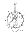
- a modified adapter generally indicated at 50 which may be removably secured to substantially any suitable life preserver 52 of a toroidal configuration.
- the adapter 50 is generally similar to the adapter 12 and comprises a scrim or cover 54 adapted to cover at least a portion of the outer surface of the body 52.
- the cover 54 may be secured in position in any suitable manner, such as by the lacing of a suitable cable or rope means 56 through a plurality of spaced ports or apertures 58 as in the manner of the cover 14 hereinbefore set forth.
- yieldable strap means 60 may be secured to the scrim or cover 54 in the same manner and to perform the same function as the strap means 28.
- Channel or sleeve means 62 is secured to the outer surface of the cover 54 for receiving the opposite ends 64 and 66 of rope means 68 therethrough.
- the rope means 68 is threaded through or passes through the yieldable straps members 60 and is operable in the same manner as the rope means 34.
- the ends 64 and 66 may be suitably secured to a suitable metallic ring 67, and the retrieving rope means 46 may be secured to the ring 67 in the same manner as hereinbefore set forth with respect to the ring 40, and for the same purpose.
- First pad or cushioning means 70 is suitably secured to the rope means 68, and preferably is interposed between two of the strap members 60 whereby the pad 70 is disposed substantially diagonally from the sleeve means 62.
- second pad or cushioning means 72 is secured to the rope means 68 in any suitable manner, and is preferably disposed in the proximity of the sleeve means 62, but not limited thereto. The pad members 70 and 72 move radially inwardly and outwardly with the actuation of the rope means 68.
- the normal stowage position for the rope means 68 and pads 70 and 72 is in the proximity of the inner periphery of the toroidal body 52.
- the device 50 When the device 50 is to be utilized for rescue of a weakened person, or the like, as hereinbefore set forth, the device may be positioned about the torso or other body portion of the victim and upon the application of pressure on the tow or retrieval line 46, the rope means 68 is drawn radially inwardly as shown in FIGURE 5 for firmly engaging the torso or other body portion of the victim and securely retaining the person in the device 50.
- the pads 70 and 72 are brought into engagement with the victim's body portion as the rope means 68 is drawn radially inwardly, thus substantially precluding injury to the body portion engaged thereby during the rescue attempt or operation.
- the normal yieldable characteristic of the strap members 60 will return the rope means 60 and pads 70 and 72 to the normal stowage positions therefor whereby the device is ready for use in a subsequent rescue operation.
- the present invention provides a novel life preserver device which may be utilized in the normal manner of toroidal devices of this type, but which is particularly designed and constructed for automatically engaging the body or body portion of a victim being rescued thereby for sustaining the victim even when he is so greatly injured or is so weakened that he cannot cling to the device of his own power.
- the novel device comprises body grasping rope means secured within the central opening of the toroidal configuration of the preserver by means of yielding strap members whereby application of a force along the length of the rope means draws the rope means tightly about the body or body portion of the victim for securely retaining the victim in the device until he may be retrieved therefrom.
- the rope means is automatically restored to a stowage position upon removal of the victim therefrom whereby the device is in a "ready condition" for the next succeeding rescue operation.
Landscapes
- Engineering & Computer Science (AREA)
- Mechanical Engineering (AREA)
- Ocean & Marine Engineering (AREA)
- Emergency Lowering Means (AREA)
- Organic Low-Molecular-Weight Compounds And Preparation Thereof (AREA)
- Coloring Foods And Improving Nutritive Qualities (AREA)
- Addition Polymer Or Copolymer, Post-Treatments, Or Chemical Modifications (AREA)
- Production Of Liquid Hydrocarbon Mixture For Refining Petroleum (AREA)
- Artificial Filaments (AREA)
- Polymers With Sulfur, Phosphorus Or Metals In The Main Chain (AREA)
- Audible And Visible Signals (AREA)
- Pharmaceuticals Containing Other Organic And Inorganic Compounds (AREA)
- Fodder In General (AREA)
- Catching Or Destruction (AREA)
- Road Signs Or Road Markings (AREA)
Claims (11)
Priority Applications (1)
| Application Number | Priority Date | Filing Date | Title |
|---|---|---|---|
| AT83902665T ATE32447T1 (de) | 1982-08-13 | 1983-07-27 | Rettungsguertel. |
Applications Claiming Priority (2)
| Application Number | Priority Date | Filing Date | Title |
|---|---|---|---|
| US407803 | 1982-08-13 | ||
| US06/407,803 US4464132A (en) | 1982-08-13 | 1982-08-13 | Life preserver |
Publications (3)
| Publication Number | Publication Date |
|---|---|
| EP0116077A1 EP0116077A1 (de) | 1984-08-22 |
| EP0116077A4 EP0116077A4 (de) | 1985-02-18 |
| EP0116077B1 true EP0116077B1 (de) | 1988-02-10 |
Family
ID=23613580
Family Applications (1)
| Application Number | Title | Priority Date | Filing Date |
|---|---|---|---|
| EP83902665A Expired EP0116077B1 (de) | 1982-08-13 | 1983-07-27 | Rettungsgürtel |
Country Status (19)
| Country | Link |
|---|---|
| US (2) | US4464132A (de) |
| EP (1) | EP0116077B1 (de) |
| JP (1) | JPS59501586A (de) |
| AT (1) | ATE32447T1 (de) |
| AU (1) | AU575539B2 (de) |
| CA (1) | CA1194731A (de) |
| DE (1) | DE3375656D1 (de) |
| DK (1) | DK156041C (de) |
| ES (1) | ES282922Y (de) |
| FI (1) | FI841130L (de) |
| GR (1) | GR77580B (de) |
| IE (1) | IE54543B1 (de) |
| IT (1) | IT1172317B (de) |
| LU (1) | LU84963A1 (de) |
| NO (1) | NO159364C (de) |
| NZ (1) | NZ205145A (de) |
| PT (1) | PT77191B (de) |
| WO (1) | WO1984000733A1 (de) |
| ZA (1) | ZA835794B (de) |
Families Citing this family (19)
| Publication number | Priority date | Publication date | Assignee | Title |
|---|---|---|---|---|
| GB2148799B (en) * | 1983-10-26 | 1987-04-01 | Trevan Hambly | Rescue apparatus |
| JP2509135Y2 (ja) * | 1988-06-29 | 1996-08-28 | スワロー産業株式会社 | ダイビング用フロ―ト被覆材 |
| US4976642A (en) * | 1989-09-15 | 1990-12-11 | Wilkie Lawrence A | Life ring |
| US5295885A (en) * | 1993-02-16 | 1994-03-22 | Karl Thomas P | Inner tube hammock/seat for water/snow recreation |
| US5433637A (en) * | 1994-06-23 | 1995-07-18 | Graves; David A. | Throwable airfoil floatation device |
| US6019651A (en) * | 1998-06-06 | 2000-02-01 | Life Safer, Inc. | Flotation device and method of using same |
| US6352461B1 (en) * | 2000-09-18 | 2002-03-05 | Lance D. Hoffman | Water rescue device and method |
| US20040144413A1 (en) * | 2002-11-13 | 2004-07-29 | Matthews John T. | Collapsible canopy and framework therefor |
| USD592363S1 (en) * | 2008-06-26 | 2009-05-12 | Ann W Price | Dog collar attachment device |
| US7967651B2 (en) * | 2009-02-16 | 2011-06-28 | John Christos Koulouris | Deployable rescue apparatus |
| US8328592B2 (en) * | 2009-03-16 | 2012-12-11 | Sam Cynamon | Flotation device for rescue apparatus and method of use |
| USD624250S1 (en) * | 2010-03-26 | 2010-09-21 | Suzanne Hamilton | Animal collar |
| USD624710S1 (en) * | 2010-03-31 | 2010-09-28 | Marilyn Moore | Dog fashion accessory |
| USD668004S1 (en) | 2012-04-23 | 2012-09-25 | Price Ann W | Dog collar attachment device |
| US8845377B2 (en) * | 2012-05-31 | 2014-09-30 | Aqua-Leisure Industries, Inc. | Floating toy construction with improved safety features |
| RU2526556C1 (ru) * | 2013-02-01 | 2014-08-27 | Виталий Григорьевич Хоруженко | Спасательный поплавок хоруженко в.г. |
| GB2521180B (en) * | 2013-12-12 | 2018-02-07 | Escape Fitness Ltd | An annular weighted exercise apparatus |
| JP5869035B2 (ja) * | 2014-04-25 | 2016-02-24 | 株式会社エクスプロア | 救命・救難装置付き浮き物体 |
| US10526061B2 (en) * | 2018-04-25 | 2020-01-07 | Taylor Made Group, Llc | Life ring and method of manufacture |
Family Cites Families (6)
| Publication number | Priority date | Publication date | Assignee | Title |
|---|---|---|---|---|
| US1780986A (en) * | 1929-03-08 | 1930-11-11 | Sipos Frank | Protective device |
| US2246108A (en) * | 1939-09-26 | 1941-06-17 | Louise L Sermon | Seat attachment for buoys |
| US2366303A (en) * | 1943-03-27 | 1945-01-02 | Harry B White | Supporting means for life preservers |
| US2529961A (en) * | 1947-05-23 | 1950-11-14 | Silas T Faust | Float |
| US3095586A (en) * | 1959-04-22 | 1963-07-02 | Ludwig S Baier | Ring buoy life preserver |
| US3869744A (en) * | 1973-09-24 | 1975-03-11 | Polyurcon Ltd | Device with attached grab line |
-
1982
- 1982-08-13 US US06/407,803 patent/US4464132A/en not_active Expired - Fee Related
-
1983
- 1983-07-27 DE DE8383902665T patent/DE3375656D1/de not_active Expired
- 1983-07-27 AT AT83902665T patent/ATE32447T1/de not_active IP Right Cessation
- 1983-07-27 JP JP58502739A patent/JPS59501586A/ja active Pending
- 1983-07-27 FI FI841130A patent/FI841130L/fi not_active Application Discontinuation
- 1983-07-27 EP EP83902665A patent/EP0116077B1/de not_active Expired
- 1983-07-27 WO PCT/US1983/001150 patent/WO1984000733A1/en not_active Ceased
- 1983-07-27 AU AU18826/83A patent/AU575539B2/en not_active Ceased
- 1983-08-04 NZ NZ205145A patent/NZ205145A/en unknown
- 1983-08-05 GR GR72134A patent/GR77580B/el unknown
- 1983-08-08 ZA ZA835794A patent/ZA835794B/xx unknown
- 1983-08-10 ES ES1983282922U patent/ES282922Y/es not_active Expired
- 1983-08-11 IT IT48844/83A patent/IT1172317B/it active
- 1983-08-12 CA CA000434472A patent/CA1194731A/en not_active Expired
- 1983-08-12 IE IE1901/83A patent/IE54543B1/en unknown
- 1983-08-12 PT PT77191A patent/PT77191B/pt not_active IP Right Cessation
- 1983-08-12 LU LU84963A patent/LU84963A1/fr unknown
-
1984
- 1984-04-02 NO NO84841291A patent/NO159364C/no unknown
- 1984-04-03 DK DK177584A patent/DK156041C/da not_active IP Right Cessation
- 1984-06-13 US US06/620,061 patent/US4540372A/en not_active Expired - Fee Related
Also Published As
| Publication number | Publication date |
|---|---|
| CA1194731A (en) | 1985-10-08 |
| ZA835794B (en) | 1984-05-30 |
| EP0116077A1 (de) | 1984-08-22 |
| US4464132A (en) | 1984-08-07 |
| NZ205145A (en) | 1985-09-13 |
| AU575539B2 (en) | 1988-08-04 |
| AU1882683A (en) | 1984-03-07 |
| JPS59501586A (ja) | 1984-09-06 |
| NO159364C (no) | 1988-12-21 |
| DK156041B (da) | 1989-06-19 |
| IT8348844A0 (it) | 1983-08-11 |
| DK177584D0 (da) | 1984-04-03 |
| PT77191B (en) | 1986-03-11 |
| IT8348844A1 (it) | 1985-02-11 |
| ES282922U (es) | 1985-09-01 |
| FI841130A0 (fi) | 1984-03-21 |
| ATE32447T1 (de) | 1988-02-15 |
| EP0116077A4 (de) | 1985-02-18 |
| DE3375656D1 (en) | 1988-03-17 |
| IE54543B1 (en) | 1989-11-08 |
| GR77580B (de) | 1984-09-24 |
| DK177584A (da) | 1984-04-03 |
| NO159364B (no) | 1988-09-12 |
| IT1172317B (it) | 1987-06-18 |
| IE831901L (en) | 1984-02-13 |
| FI841130A7 (fi) | 1984-03-21 |
| LU84963A1 (fr) | 1983-12-28 |
| PT77191A (en) | 1983-09-01 |
| ES282922Y (es) | 1986-05-01 |
| DK156041C (da) | 1989-11-06 |
| NO841291L (no) | 1984-04-02 |
| US4540372A (en) | 1985-09-10 |
| WO1984000733A1 (en) | 1984-03-01 |
| FI841130L (fi) | 1984-03-21 |
Similar Documents
| Publication | Publication Date | Title |
|---|---|---|
| EP0116077B1 (de) | Rettungsgürtel | |
| US5421757A (en) | Rescue raft | |
| US4976642A (en) | Life ring | |
| US5839932A (en) | Multi-purpose aquatic rescue gear | |
| US4863409A (en) | Method and apparatus for aid in lifesaving operations on water | |
| US4661077A (en) | Lifesaving and mooring device | |
| US7306501B2 (en) | Inflatable aquatic rescue collar | |
| EP0145461A2 (de) | Rettungsmittel | |
| US5468167A (en) | Life raft utility tether | |
| US6475047B2 (en) | Rescue device | |
| JPH10502311A (ja) | 人命救助具 | |
| JPH03284498A (ja) | ネット状救命機器 | |
| JP7268146B2 (ja) | 水難救助用馬蹄形救命ブイ及び関連する救助ロープアセンブリ | |
| US5480332A (en) | Multiple victim rescue device | |
| EP1937545B1 (de) | Auftriebs- und rettungsvorrichtung | |
| US4701145A (en) | Life-saving device | |
| US20030176122A1 (en) | Method and device for rescuing injured people | |
| JP2004122967A (ja) | 救助用ロープ | |
| WO1997032776A1 (en) | Method and equipment for securing a person, for marine use | |
| US6352461B1 (en) | Water rescue device and method | |
| WO2015088438A1 (en) | Life-saving device | |
| GB2268123A (en) | Rescue apparatus | |
| WO2023194791A1 (en) | Compact transportable flotation device with support for victim's head and shoulder girdle | |
| GB2594475A (en) | Life safety device for rescuing a person from a body of water | |
| GB2388093A (en) | Buoyant protective sleeve for a boom which can be used as a lifesaving device |
Legal Events
| Date | Code | Title | Description |
|---|---|---|---|
| PUAI | Public reference made under article 153(3) epc to a published international application that has entered the european phase |
Free format text: ORIGINAL CODE: 0009012 |
|
| AK | Designated contracting states |
Designated state(s): AT BE CH DE FR GB LI NL SE |
|
| 17P | Request for examination filed |
Effective date: 19840830 |
|
| GRAA | (expected) grant |
Free format text: ORIGINAL CODE: 0009210 |
|
| AK | Designated contracting states |
Kind code of ref document: B1 Designated state(s): AT BE CH DE FR GB LI NL SE |
|
| PG25 | Lapsed in a contracting state [announced via postgrant information from national office to epo] |
Ref country code: NL Effective date: 19880210 Ref country code: LI Effective date: 19880210 Ref country code: CH Effective date: 19880210 Ref country code: AT Effective date: 19880210 |
|
| REF | Corresponds to: |
Ref document number: 32447 Country of ref document: AT Date of ref document: 19880215 Kind code of ref document: T |
|
| PG25 | Lapsed in a contracting state [announced via postgrant information from national office to epo] |
Ref country code: SE Effective date: 19880229 |
|
| REF | Corresponds to: |
Ref document number: 3375656 Country of ref document: DE Date of ref document: 19880317 |
|
| REG | Reference to a national code |
Ref country code: CH Ref legal event code: PL |
|
| EN | Fr: translation not filed | ||
| NLV1 | Nl: lapsed or annulled due to failure to fulfill the requirements of art. 29p and 29m of the patents act | ||
| PLBE | No opposition filed within time limit |
Free format text: ORIGINAL CODE: 0009261 |
|
| STAA | Information on the status of an ep patent application or granted ep patent |
Free format text: STATUS: NO OPPOSITION FILED WITHIN TIME LIMIT |
|
| 26N | No opposition filed | ||
| PGFP | Annual fee paid to national office [announced via postgrant information from national office to epo] |
Ref country code: DE Payment date: 19890706 Year of fee payment: 7 |
|
| PGFP | Annual fee paid to national office [announced via postgrant information from national office to epo] |
Ref country code: FR Payment date: 19890707 Year of fee payment: 7 |
|
| PGFP | Annual fee paid to national office [announced via postgrant information from national office to epo] |
Ref country code: BE Payment date: 19890714 Year of fee payment: 7 |
|
| PGFP | Annual fee paid to national office [announced via postgrant information from national office to epo] |
Ref country code: GB Payment date: 19890731 Year of fee payment: 7 |
|
| PG25 | Lapsed in a contracting state [announced via postgrant information from national office to epo] |
Ref country code: GB Effective date: 19900727 |
|
| PG25 | Lapsed in a contracting state [announced via postgrant information from national office to epo] |
Ref country code: BE Effective date: 19900731 |
|
| BERE | Be: lapsed |
Owner name: MAUCK LEE EDWARD Effective date: 19900731 |
|
| GBPC | Gb: european patent ceased through non-payment of renewal fee | ||
| PG25 | Lapsed in a contracting state [announced via postgrant information from national office to epo] |
Ref country code: DE Effective date: 19910403 |
|
| PG25 | Lapsed in a contracting state [announced via postgrant information from national office to epo] |
Ref country code: FR Free format text: LAPSE BECAUSE OF NON-PAYMENT OF DUE FEES Effective date: 19900731 |