EP0116325B1 - Dosiervorrichtung für Flüssigkeiten für Infusions- oder Transfusionsgeräte - Google Patents
Dosiervorrichtung für Flüssigkeiten für Infusions- oder Transfusionsgeräte Download PDFInfo
- Publication number
- EP0116325B1 EP0116325B1 EP84100863A EP84100863A EP0116325B1 EP 0116325 B1 EP0116325 B1 EP 0116325B1 EP 84100863 A EP84100863 A EP 84100863A EP 84100863 A EP84100863 A EP 84100863A EP 0116325 B1 EP0116325 B1 EP 0116325B1
- Authority
- EP
- European Patent Office
- Prior art keywords
- housing
- metering device
- hose member
- pressing element
- hose
- Prior art date
- Legal status (The legal status is an assumption and is not a legal conclusion. Google has not performed a legal analysis and makes no representation as to the accuracy of the status listed.)
- Expired
Links
- 238000001802 infusion Methods 0.000 title claims abstract description 14
- 239000007788 liquid Substances 0.000 title claims description 34
- 239000012530 fluid Substances 0.000 claims abstract description 6
- 238000006073 displacement reaction Methods 0.000 claims abstract description 4
- 230000001154 acute effect Effects 0.000 claims description 3
- 239000013536 elastomeric material Substances 0.000 claims description 3
- 238000002347 injection Methods 0.000 description 8
- 239000007924 injection Substances 0.000 description 8
- 230000008719 thickening Effects 0.000 description 8
- 239000003814 drug Substances 0.000 description 3
- 229940079593 drug Drugs 0.000 description 3
- 238000003780 insertion Methods 0.000 description 3
- 230000037431 insertion Effects 0.000 description 3
- 239000013013 elastic material Substances 0.000 description 2
- 238000001990 intravenous administration Methods 0.000 description 2
- 239000004033 plastic Substances 0.000 description 2
- 230000001954 sterilising effect Effects 0.000 description 2
- 238000004659 sterilization and disinfection Methods 0.000 description 2
- 239000004743 Polypropylene Substances 0.000 description 1
- 230000006378 damage Effects 0.000 description 1
- 229920001971 elastomer Polymers 0.000 description 1
- 239000000806 elastomer Substances 0.000 description 1
- 230000002349 favourable effect Effects 0.000 description 1
- 210000003811 finger Anatomy 0.000 description 1
- 230000002093 peripheral effect Effects 0.000 description 1
- -1 polypropylene Polymers 0.000 description 1
- 229920001155 polypropylene Polymers 0.000 description 1
- 230000001105 regulatory effect Effects 0.000 description 1
- 210000003813 thumb Anatomy 0.000 description 1
Images


Classifications
-
- A—HUMAN NECESSITIES
- A61—MEDICAL OR VETERINARY SCIENCE; HYGIENE
- A61M—DEVICES FOR INTRODUCING MEDIA INTO, OR ONTO, THE BODY; DEVICES FOR TRANSDUCING BODY MEDIA OR FOR TAKING MEDIA FROM THE BODY; DEVICES FOR PRODUCING OR ENDING SLEEP OR STUPOR
- A61M39/00—Tubes, tube connectors, tube couplings, valves, access sites or the like, specially adapted for medical use
- A61M39/22—Valves or arrangement of valves
- A61M39/28—Clamping means for squeezing flexible tubes, e.g. roller clamps
- A61M39/285—Cam clamps, e.g. roller clamps with eccentric axis
Definitions
- the invention relates to a dosing device for liquids for infusion or transfusion devices with a flexible liquid line passing through a housing, which contains a tube piece made of highly elastic elastomeric material inside the housing, and with a pressing element supported on the housing for compressing the tube piece.
- a container containing the infusion or transfusion liquid with a downward-pointing opening and a connected liquid line is usually suspended so high that the liquid pressure in the line is higher than the venous pressure of the patient.
- the liquid is first fed to an intermediate container in the liquid line and from there to the patient. Due to the different boundary conditions, e.g. the venous pressure of the patient, the viscosity of the liquid, and the different filling level of the liquid container as well as due to therapeutically necessary specific doses of the liquid, it is necessary to precisely regulate the flow rate of the liquid.
- a liquid line has a line section made of elastic material which can be pressed together with a pressing element supported on a housing.
- the elastic hose element is guided through an opening in the housing that is larger than the cross section of the hose section.
- the inner opening of the tube piece is not a circular cross section, but has a plurality of radially uniformly distributed and axially extending V-shaped grooves.
- Such a piece of hose cannot consequently completely prevent the flow even in the fully compressed state.
- a displacement within the housing of the pressing element is possible, since the piece of hose cannot be locked on the housing.
- Dosing devices of the type mentioned at the outset are known with a liquid line passing through a housing and a clamping element which consists of a roller which is guided in the housing and presses on the hose cross section (DE-A-2 637 495).
- the metering amount which is usually determined as the number of drops of liquid falling into the intermediate container per unit of time, cannot be kept constant over a long period of time with such devices, since the PVC hoses that are usually used can deform due to their tendency to creep (cold fluidity) .
- a metering device with a housing and a substantially cylindrical valve chamber provided in the housing, two connection ports, each projecting from the housing and the valve chamber in radially opposite directions, and a plug which can be rotated with a handle and which Valve chamber is used sealingly.
- a passage is provided in the lateral surface of the plug which, depending on the rotational position of the plug, releases flow cross-sections of different sizes between the connecting pieces (DE-A-2 735 955).
- the invention has for its object to provide a metering device of the type mentioned that allows an exact, time-constant and reproducible adjustable dosage of liquids even with a piece of tubing with a circular inner cross section and injection of injection liquids.
- the tube piece has a thickening over part of its length, that the housing is secured against longitudinal displacement on the thickening of the tube piece, and that the pressing element acts on the tube piece outside the region of the thickening.
- the liquid line can be made in the previous manner from a suitable plastic. At a suitable point, it contains an elastomeric piece of tubing which is surrounded by a housing and which, together with this housing, a pressing element and an adjusting device, forms the metering device.
- the hose section has a high elasticity and restoring force, so that the cross-sectional area of the hose section always strives to achieve its relaxed original state, provided that the regulating element of the metering device, here a pressing element, allows it.
- a change in the position of the pressure element causes an immediate change in the flow cross-section of the hose section, even if the pressure element has been reset.
- the dosing device according to the invention guarantees - in the case of intravenous infusion and transfusion devices an essential safety aspect - a high degree of tightness against air entry because the flow-regulating device, here the piece of tubing, consists of one piece.
- the dosing device can be manufactured inexpensively.
- the housing is produced in one piece as an injection molded part. The housing and the actuating device as well as the pushing element do not need to be sterilized because only the tube piece comes into contact with the infusion or transfusion liquid, which reduces the costs the sterilization of the dosing device and the risks of poor sterilization.
- the tube piece can also be used to inject additional medication or liquids with a syringe.
- the tube piece consists of a highly elastic, elastomeric material ensures that the metering device remains sealed even after the needle cannula has been inserted and withdrawn.
- the thickening of the tube piece allows greater freedom in the cavity of the tube piece with regard to the insertion depth of the needle cannula and thus increases the safety of the device.
- the piece of tubing is therefore of double use in that, on the one hand, it offers the possibility of injecting medication or liquids and, on the other hand, by metering the flow rate of the infusion or transfusion liquid in conjunction with the pressure element. Otherwise two hose sections are required for these tasks.
- a preferred embodiment of the invention is characterized in that the pressing element is guided transversely to the longitudinal direction of the tube piece and that the front side of the pressing element pressing against the tube piece is inclined to the direction of movement of the pressing element.
- Such an asymmetrical deformation of the hose section has the advantage of successively clamping the hose section from one side, thereby preventing the hose section from having a different cross-sectional shape, e.g. B. in the form of an eight, despite the elasticity maintains its deformation or changes its cross-sectional shape by leaps and bounds. This ensures a particularly exact, reproducible adjustable dosage.
- An advantageous development of the invention is characterized in that the housing has a puncture channel for a needle cannula leading to the tube piece. In this way, the needle cannula is fed to a specific point on the tube piece.
- a preferred embodiment of the invention is characterized in that the puncture channel runs at an acute angle to the longitudinal axis of the tube piece. This has the advantage that the most favorable insertion angle is maintained due to the guidance of the needle cannula. This increases the safety when injecting, since a maximum free path for the needle tip in the tube piece is achieved. This is important when the need to inject particularly quickly in emergencies, since the needle tip is positioned more easily and safely in the cross-section of the tube, and the further tube wall cannot be perforated if the needle is inserted too deeply, as a result of which the injection fluid would not get into the bloodstream.
- the pressing element can be moved via a manually adjustable self-locking adjusting device.
- the adjusting device can preferably consist of a threaded spindle mounted in the housing. With a threaded spindle, depending on the thread pitch, a particularly precise and reproducible dosage is possible.
- the adjusting device can also have a removable handle part. This significantly increases the security against unauthorized adjustment of the metering device, since it cannot be adjusted when the handle part is removed.
- the exemplary embodiments of a metering device 1 shown in FIGS. 1 to 9 are arranged in an infusion or transfusion device.
- the dosing device 1 in the liquid line 2 is consequently between an infusion container and a patient. It has a housing 3 for receiving an adjusting device 4, a pressing element 5 and a piece of hose 6 inserted into the liquid line 2.
- the hose piece 6 is a commercially available injection part made of a highly elastic elastomer, which is usually interposed in a PVC liquid line 2 in order to offer the possibility, e.g. Inject medication during an infusion or transfusion.
- the elastic hose piece 6 overlaps the ends of the liquid line 2 with its two ends 63, 64 in an airtight manner.
- the tube piece 6 has in its central part a thickening 65 which is reduced at its two ends in the form of an annular shoulder 61, 62 to a cylindrical tube section 63, 64 which is somewhat larger than the cross section of the liquid line 2.
- This thickening 65 fixes the position of the entire metering device 1 at a certain one Place in the liquid line 2. It also allows the wall thickness to be increased. This is important if the hose section 6 in the metering device 1 is also to be used for injection.
- the thickening 65 creates the longest possible path in the cavity 60 of the tube piece 6 for the insertion of a needle cannula (not shown).
- the highly elastic material of the tube piece 6 ensures that the puncture hole closes again immediately after piercing the wall 'of the tube piece 6 with a needle cannula and after pulling out this needle cannula.
- the housing 3 forms a chamber 7 in which the tube piece 6 is inserted.
- the chamber 7 is essentially adapted to the outer contour of the tube piece 6 and has a nozzle 71 in the area of the thin cylindrical tube section 63 and a channel 72 in the area of the thin cylindrical tube section 64.
- the annular shoulders 61, 62 of the hose section 6 each adjoin a wall of the chamber 7, so that the position of the hose section 6 is thereby determined.
- a puncture channel 8 for guiding a needle cannula to the chamber 7 runs through the housing 3 at an acute angle relative to the longitudinal axis of the housing. This puncture channel 8 opens directly in front of the annular shoulder 61 of the hose section 6, which is formed by the step-shaped thickening 65 of the hose section 6 .
- the exemplary embodiments of the metering device 1 of FIGS. 1 to 8 use as a pressing element a cuboid-shaped metering wedge 5, which presses on its wide sides in a straight guide path 32 running at right angles to the hose piece onto the cylindrical hose section 64 shortly before the annular shoulder 61 of the hose piece 6.
- the end face 51 of the dosing wedge 5 presses the hose section 64 in the direction of the flat bottom surface of the channel 72. It extends obliquely to this bottom surface in the cross-sectional plane of the hose section 6. In this way, the hose section 64 is increasingly clamped from one side when the metering wedge 5 is delivered.
- the dosing wedge 5 is actuated by an adjusting device 4, the resetting being carried out on the basis of the elastic restoring force of the tube piece 6.
- the setting device 5 can, for example, as shown in FIGS. 1 to 4, be a threaded spindle 40, which is located in a thread 33 of the housing 30 and is actuated by a setting wheel 41.
- the adjusting wheel 41 engages e.g. with a hexagon 42 in a corresponding recess 43 in the interior of the threaded spindle 40. This positive connection is releasable and therefore enables the setting wheel 41 to be removed, e.g.
- a hollow cylinder 44 projecting coaxially from the adjusting wheel 41 with the hexagon 42 and fitting into a corresponding hollow cylindrical recess 34 in the housing part 3a serves to guide the adjusting wheel 41 and prevents the hexagon 42 from breaking off due to tilting.
- the adjusting device 4 consists of an eccentric 45 which is fastened on an eccentric shaft 46.
- the eccentric shaft 46 is held on the one hand by the bearing 35 in the housing 3a, and on the other hand is received by a key part 48 of the adjusting wheel 47, which in turn is mounted in the housing 36 with the key part 48.
- the eccentric shaft 46 is positively and releasably connected to the adjusting wheel 47 and in its part 49 encompassed by the key part 48 of the adjusting wheel 47, for. B. formed as a square or hexagon.
- this adjusting device is also designed to be self-locking, so that the adjusting wheel 41 cannot be adjusted by itself.
- the remaining parts of this metering device 1 correspond to the previous embodiment.
- This lever 90 is articulated on the housing 3a at an articulation point 97 on one side with its long leg 92 such that the long one Leg 92 assumes a position inclined to the housing wall 36 in the relaxed undeformed state of the hose section 6.
- the slide 93 is inserted, which is supported with its part located in the housing 3 on the housing wall 36 and thereby presses on the long leg 92 of the lever 90.
- the slide 93 If the slide 93 is moved away from the articulation point 97 of the lever 90, it presses increasingly on the long leg 92 like a wedge due to the inclination of the lever 90, so that the short leg 91 of the lever 90, which is angled at almost a right angle, increasingly presses on the tube piece 6 .
- the end face 98 of the short leg 91 of the lever 90 acting on the hose section 6 is beveled transversely to the hose direction in accordance with the metering wedge 5, so that the hose section 6 is increasingly clamped from one side when the lever 90 is pivoted into the closed position.
- the slide 93 is guided in a slot 37 in the upper housing wall 36.
- the inside 39 of the housing wall 36 is ribbed so that a self-locking of the adjusting device is achieved in connection with the ribbed surface 95 of the part 94 of the slide 93 located in the housing 3.
- the obree part 96 of the slide 93 can also be removable in accordance with the setting wheels 41, 47 of the previous exemplary embodiments, in order to prevent unauthorized actuation of the metering device 1 by unauthorized persons.
- the housing 3 is an injection molded part in one piece, for. B. made of polypropylene. All of the housings shown are designed in such a way that they have two housing parts 3a, 3b which can be pivoted in the longitudinal direction, for example about a film hinge 39 (FIGS. 4, 8, 9).
- the two housing parts 3a, 3b can be combined press together with the help of snap connections 31 a, 31 b. After the two housing parts 3a, 3b have been pressed together, the connection can no longer be released without destruction.
- the two housing parts have a handle 38 running parallel to the liquid line 2, which enables one-hand operation of the adjusting device 4 in combination with an adjusting wheel 41, 47 or a slide 93.
- the outer wheels of the adjusting wheels 41, 47 and the slide 93 are shaped in such a way that they can easily be operated with the thumb, while the other fingers of the hand encompass the grip piece 38 on the housing 3.
Landscapes
- Health & Medical Sciences (AREA)
- Heart & Thoracic Surgery (AREA)
- Pulmonology (AREA)
- Engineering & Computer Science (AREA)
- Anesthesiology (AREA)
- Biomedical Technology (AREA)
- Hematology (AREA)
- Life Sciences & Earth Sciences (AREA)
- Animal Behavior & Ethology (AREA)
- General Health & Medical Sciences (AREA)
- Public Health (AREA)
- Veterinary Medicine (AREA)
- Infusion, Injection, And Reservoir Apparatuses (AREA)
Description
- Die Erfindung betrifft eine Dosiervorrichtung für Flüssigkeiten für Infusions- oder Transfusionsgeräte mit einer durch ein Gehäuse hindurchgehenden flexiblen Flüssigkeitsleitung, die im Innern des Gehäuses ein Schlauchstück aus hochelastischem elastomerem Material enthält, und mit einem am Gehäuse abgestützten Drückelement zum Zusammendrücken des Schlauchstückes.
- Bei der Durchführung von Infusionen oder Transfusionen wird üblicherweise ein die Infusions- oder Transfusionsflüssigkeit enthaltender Behälter mit nach unten weisender Öffnung und angeschlossener Flüssigkeitsleitung so hoch aufgehängt, dass der Flüssigkeitsdruck in der Leitung höher ist als der Venendruck des Patienten. Die Flüssigkeit wird zunächst einem Zwischenbehälter in der Flüssigkeitsleitung zugeführt und gelangt von dort zum Patienten. Aufgrund der unterschiedlichen Randbedingungen, z.B. des Venendruckes des Patienten, der Viskosität der Flüssigkeit, und der unterschiedlichen Füllhöhe des Flüssigkeitsbehälters sowie aufgrund therapeutisch notwendiger bestimmter Dosierungen der Flüssigkeit, ist es erforderlich, die Durchflussmenge der Flüssigkeit exakt zu regeln.
- Bei einer bekannten Dosiervorrichtung für Flüssigkeiten bei intravenösen Infusionen (DE-A-2 340 611) weist eine Flüssigkeitsleitung einen Leitungsabschnitt aus elastischem Material auf, der mit einem an einem Gehäuse abgestützten Drückelement zusammengedrückt werden kann. Dabei ist das elastische Schlauchelement durch eine Öffnung des Gehäuses geführt, die grösser als der Querschnitt des Schlauchstückes ist. Die innere Öffnung des Schlauchstückes ist nicht kreisförmigen Querschnitts, sondern weist mehrere radial gleichmässig verteilte und axial verlaufende V-förmige Rillen auf. Ein derartiges Schlauchstück kann folglich selbst im restlos zusammengedrückten Zustand den Durchfluss nicht vollständig unterbinden. Ferner ist eine Verschiebung innerhalb des Gehäuses des Drückelementes möglich, da das Schlauchstück nicht am Gehäuse arretiert werden kann.
- Bekannt sind Dosiervorrichtungen der eingangs genannten Art mit einer durch ein Gehäuse hindurchgehenden Flüssigkeitsleitung und einem Klemmelement, das aus einer in dem Gehäuse geführten und auf den Schlauchquerschnitt drückenden Rolle besteht (DE-A-2 637 495). Die Dosiermenge, die üblicherweise als die Anzahl der in den Zwischenbehälter pro Zeiteinheit fallenden Flüssigkeitstropfen ermittelt wird, lässt sich mit derartigen Vorrichtungen nicht über einen längeren Zeitraum konstant halten, da sich die üblicherweise verwendeten PVC-Schläuche infolge ihrer Neigung zum Kriechen (Kaltfliessvermögen) verformen können. Insbesondere treten Probleme auf, wenn die Dosiermenge wieder erhöht werden soll und die Flüssigkeitsleitung zuvor längere Zeit zusammengedrückt war, da das zähelastische und nicht hysteresefreie Relaxationsverhalten der Kunststoffleitung eine schnelle Rückkehr in den ursprünglichen Leitungsquerschnitt verhindert. Daher kann bei derartigen Dosiervorrichtungen oft selbst bei ständiger Regulierung eine konstante Dosierung nicht erreicht werden.
- Bekannt ist ferner eine Dosiervorrichtung mit einem Gehäuse und einem in dem Gehäuse vorgesehenen im wesentlichen zylindrischen Ventilraum, zwei von dem Gehäuse bzw. dem Ventilraum radial nach entgegengesetzten Richtungen abstehenden, jeweils einen Kanal aufweisenden Anschlussstutzen, und einem mit einem Handgriff drehbaren Küken, das in dem Ventilraum abdichtend eingesetzt ist. In der Mantelfläche des Kükens ist ein Durchlass vorgesehen, der in Abhängigkeit von der Drehstellung des Kükens unterschiedlich grosse Durchflussquerschnitte zwischen den Anschlussstutzen freigibt (DE-A-2 735 955). Bei derartigen Dosiervorrichtungen muss ein hoher konstruktiver Aufwand betrieben werden, um eine sichere Abdichtung der Dosiervorrichtung gegen Lufteintritt zu gewährleisten.
- Der Erfindung liegt die Aufgabe zugrunde, eine Dosiervorrichtung der eingangs genannten Art zu schaffen, die eine exakte, zeitkonstante und reproduzierbar einstellbare Dosierung von Flüssigkeiten auch bei einem Schlauchstück mit kreisförmigem Innenquerschnitt sowie ein Zuspritzen von Injektionsflüssigkeiten erlaubt.
- Zur Lösung dieser Aufgabe ist erfindungsgemäss vorgesehen, dass das Schlauchstück auf einem Teil seiner Länge eine Verdickung aufweist, dass das Gehäuse an der Verdickung des Schlauchstückes gegen Längsverschiebung gesichert ist und dass das Drückelement ausserh'alb des Bereiches der Verdickung an dem Schlauchstück angreift.
- Die Flüssigkeitsleitung kann in der bisherigen Weise aus geeignetem Kunststoff hergestellt sein. Sie enthält an einer geeigneten Stelle ein elastomeres Schlauchstück, das von einem Gehäuse umgeben ist und das gemeinsam mit diesem Gehäuse, einem Drückelement und einer Stellvorrichtung die Dosiervorrichtung bildet. Das Schlauchstück weist eine hohe Elastizität und Rückstellkraft auf, so dass die Querschnittsfläche des Schlauchstückes immer bestrebt ist, ihren entspannten Ursprungszustand zu erreichen, soweit es das Regelelement der Dosiervorrichtung, hier ein Drückelement, zulässt. Eine Änderung der Position des Drückelementes bewirkt eine sofortige Änderung des Durchflussquerschnittes des Schlauchstückes, auch wenn das Drückelement zurückgestellt wurde. Auf diese Weise wird eine sehr hohe Dosiergenauigkeit erreicht, die eine weitgehend zeitkonstante Tropfgeschwindigkeit der Flüssigkeit erlaubt, und die reproduzierbar eingestellt werden kann. Die erfindungsgemässe Dosiervorrichtung garantiert - bei intravenösen Infusions- und Transfusionsgeräten ein wesentlicher Sicherheitsaspekt - in hohem Masse eine Dichtigkeit gegen Lufteintritt, weil die durchflussregelnde Vorrichtung, hier das Schlauchstück, aus einem Stück besteht. Die Dosiervorrichtung lässt sich kostengünstig herstellen. Das Gehäuse wird in einstückiger Fertigung als Spritzgussteil produziert. Das Gehäuse und die Stellvorrichtung sowie das Drückelement brauchen nicht sterilisiert zu werden, weil nur das Schlauchstück mit der Infusions- oder Transfusionsflüssigkeit in Berührung kommt, wodurch die Kosten der Sterilisation der Dosiervorrichtung und die Gefahren einer mangelhaften Sterilisation vermieden werden.
- Aufgrund der Form des Schlauchstückes ist die Position des Gehäuses exakt fixiert. Ein wesentlicher Vorteil ist, dass das Schlauchstück als Zuspritzteil bekannt und handelsüblich ist und daher keine speziellen Teile notwendig sind. In der erfindungsgemässen Dosiervorrichtung kann das Schlauchstück ebenfalls zum Zuspritzen zusätzlicher Medikamente oder Flüssigkeiten mit einer Spritze verwendet werden. Dadurch, dass das Schlauchstück aus einem hochelastischen elastomeren Material besteht, ist die Dichtigkeit der Dosiervorrichtung auch nach dem Einstechen und Herausziehen der Nadelkanüle gewährleistet. Die Verdickung des Schlauchstückes ermöglicht einen grösseren Spielraum im Hohlraum des Schlauchstückes hinsichtlich der Einstichtiefe der Nadelkanüle und erhöht damit die Sicherheit der Vorrichtung.
- Das Schlauchstück ist folglich von doppeltem Nutzen, indem es einerseits die Möglichkeit bietet, Medikamente oder Flüssigkeiten zuzuspritzen und indem es andererseits in Verbindung mit dem Drückelement die Durchflussmenge der Infusions- bzw. Transfusionsflüssigkeit dosiert. Für diese Aufgaben werden sonst zwei Schlauchabschnitte benötigt.
- Ein bevorzugtes Ausführungsbeispiel der Erfindung ist dadurch gekennzeichnet, dass das Drückelement quer zur Längsrichtung des Schlauchstükkes geführt ist und dass die gegen das Schlauchstück drückende Vorderseite des Drückelementes zur Bewegungsrichtung des Drückelementes schräggestellt ist. Eine derartige asymmetrische Verformung des Schlauchstückes hat den Vorteil, das Schlauchstück sukzessive von einer Seite her zu klemmen, wodurch verhindert wird, dass das Schlauchstück in einer anderen Querschnittsform, z. B. in Form einer Acht, trotz der Elastizität seine Verformung beibehält oder sprunghaft seine Querschnittsform ändert. Dies gewährleistet eine besonders exakte, reproduzierbar einstellbare Dosierung.
- Eine vorteilhafte Weiterbildung der Erfindung ist dadurch gekennzeichnet, dass das Gehäuse einen zum Schlauchstück führenden Einstichkanal für eine Nadelkanüle aufweist. Auf diese Weise wird die Nadelkanüle einer bestimmten Stelle des Schlauchstükkes zugeführt.
- Eine bevorzugte Ausführungsform der Erfindung ist dadurch gekennzeichnet, dass der Einstichkanal unter einem spitzen Winkel zur Längsachse des Schlauchstückes verläuft. Dies hat den Vorteil, dass aufgrund der Führung der Nadelkanüle der günstigste Einstichwinkel eingehalten wird. Dadurch wird die Sicherheit beim Zuspritzen erhöht, da ein maximaler freier Weg für die Nadelspitze im Schlauchstück erzielt wird. Dies ist wichtig, wenn in Notfällen besonders schnell zugespritzt werden muss, da die Nadelspitze leichter und sicherer im Schlauchquerschnitt positioniert und nicht durch ein zu tiefes Einstechen auch noch die weitere Schlauchwand perforiert werden kann, wodurch die Zuspritzflüssigkeit nicht in den Blutkreislauf gelangen würde.
- Bei einer vorteilhaften Weiterbildung der Erfindung ist vorgesehen, dass das Drückelement über eine manuell verstellbare selbsthemmende Stellvorrichtung bewegbar ist. Die Stellvorrichtung kann bevorzugt aus einer im Gehäuse gelagerten Gewindespindel bestehen. Mit einer Gewindespindel ist je nach Gewindesteigung eine besonders genaue und reproduzierbare Dosierung möglich.
- Die Stellvorrichtung kann auch ein abnehmbares Griffteil haben. Dies erhöht wesentlich die Sicherheit gegen unerlaubtes Verstellen der Dosiervorrichtung, da sie bei abgenommenem Griffteil nicht verstellt werden kann.
- Weitere vorteilhafte Ausgestaltungen der Erfindung sind den Ansprüchen 4, 8 und 9 zu entnehmen.
- Im folgenden werden unter Bezugnahme auf die Zeichnungen Ausführungsbeispiele der Erfindung näher erläutert.
- Es zeigen:
- Fig. 1 einen Längsschnitt durch eine Dosiervorrichtung, mit einer Gewindespindel als Stellvorrichtung,
- Fig. 2 eine Draufsicht auf diese Dosiervorrichtung,
- Fig. 3 einen Schnitt entlang der Linie 111-111 in Fig. 1,
- Fig. 4 eine perspektivische Explosionsdarstellung der Dosiervorrichtung gemäss Fig. 1 mit auseinandergeklappten Gehäusehälften,
- Fig. 5 einen Längsschnitt durch eine Dosiervorrichtung mit einem Exzenter als Stellvorrichtung,
- Fig. 6 eine Draufsicht der Dosiervorrichtung gemäss Fig. 5,
- Fig. 7 einen Schnitt entlang der Linie VII-VII in Fig. 5,
- Fig. 8 eine perspektivische Explosionsdarstellung der Dosiervorrichtung gemäss Fig. 5 mit auseinandergeklappten Gehäusehälften und
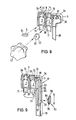
- Fig. 9 eine perspektivische Darstellung einer Dosiervorrichtung mit einem Hebel als Stellvorrichtung mit auseinandergeklappten Gehäusehälften.
- Die in den Figuren 1 bis 9 gezeigten Ausführungsbeispiele einer Dosiervorrichtung 1 sind in einer Infusions- oder Transfusionseinrichtung angeordnet. Die Dosiervorrichtung 1 in der Flüssigkeitsleitung 2 befindet sich folglich zwischen einem Infusionsbehälter und einem Patienten. Sie weist ein Gehäuse 3 zur Aufnahme einer Stellvorrichtung 4, eines Drückelementes 5 und eines in die Flüssigkeitsleitung 2 eingefügten Schlauchstückes 6 auf.
- Das Schlauchstück 6 ist ein handelsüblicher Zuspritzteil aus einem hochelastischen Elastomer, das üblicherweise in einer PVC-Flüssigkeitsleitung 2 zwischengeschaltet wird, um die Möglichkeit zu bieten, z.B. Medikamente bei einer Infusion oder Transfusion zuzusspritzen. Zum Anschluss an die herkömmliche PVC-Flüssigkeitsleitung 2 überlappt das elastische Schlauchstück 6 mit seinen beiden Enden 63, 64 jeweils die Enden der Flüssigkeitsleitung 2 luftdicht.
- Es können auch Verbindungsstutzen eingesetzt werden, wie sie schon an den herkömmlichen Infusionsgeräten verwendet werden. Das Schlauchstück 6 weist in seinem mittleren Teil eine Verdikkung 65 auf, die an ihren beiden Enden jeweils in Form einer Ringschulter 61, 62 auf einen zylindrischen Schlauchabschnitt 63, 64 reduziert ist, der etwas grösser ist als der Querschnitt der Flüssigkeitsleitung 2. Diese Verdickung 65 fixiert die Lage der gesamten Dosiervorrichtung 1 an einer bestimmten Stelle in der Flüssigkeitsleitung 2. Sie ermöglicht auch eine Verstärkung der Wandstärke. Dies ist von Bedeutung, wenn das Schlauchstück 6 in der Dosiervorrichtung 1 ebenfalls zum Zuspritzen verwendet werden soll. Andererseits schafft die Verdickung 65 einen möglichst langen freien Weg im Hohlraum 60 des Schlauchstückes 6 für den Einstich einer (nicht dargestellten) Nadelkanüle. Das hochelastische Material des Schlauchstückes 6 gewährleistet, dass sich das Einstichloch nach Durchstechen der Wand ' des Schlauchstückes 6 mit einer Nadelkanüle und nach Herausziehen dieser Nadelkanüle sofort wieder schliesst.
- Das Gehäuse 3 bildet im geschlossenen Zustand eine Kammer 7, in der das Schlauchstück 6 eingefügt ist. Die Kammer 7 ist der Aussenkontur des Schlauchstückes 6 im wesentlichen angepasst und weist im Bereich des dünnen zylindrischen Schlauchabschnittes 63 einen Stutzen 71 und im Bereich des dünnen zylindrischen Schlauchabschnittes 64 einen Kanal 72 auf. Die Ringschultern 61, 62 des Schlauchstückes 6 grenzen jeweils an eine Wand der Kammer 7, so dass die Lage des Schlauchstückes 6 dadurch festgelegt ist. Durch das Gehäuse 3 verläuft in einem spitzen Winkel relativ zur Längsachse des Gehäuses ein Einstichkanal 8 zur Führung einer Nadelkanüle bis zur Kammer 7. Dieser Einstichkanal 8 mündet unmittelbar vor der Ringschulter 61 des Schlauchstückes 6, die durch die stufenförmige Verdickung 65 des Schlauchstückes 6 gebildet wird.
- Die Ausführungsbeispiele der Dosiervorrichtung 1 der Fig. 1 bis 8 verwenden als Drückelement einen quaderförmigen Dosierkeil 5, der an seinen breiten Seiten in einer geradlinigen und rechtwinklig zum Schlauchstück verlaufenden Führungsbahn 32 auf den zylindrischen Schlauchabschnitt 64 kurz vor der Ringschulter 61 des Schlauchstückes 6 drückt. Die Stirnfläche 51 des Dosierkeils 5 drückt den Schlauchabschnitt 64 in Richtung auf die ebene Bodenfläche des Kanals 72. Sie verläuft in der Querschnittsebene des Schlauchstückes 6 schräg zu dieser Bodenfläche. Auf diese Weise wird der Schlauchabschnitt 64 bei Zustellen des Dosierkeils 5 von der einen Seite zunehmend geklemmt.
- Der Dosierkeil 5 wird von einer Stellvorrichtung 4 betätigt, wobei die Rückstellung aufgrund der elastischen Rückstellkraft des Schlauchstückes 6 erfolgt. Die Stellvorrichtung 5 kann beispielsweise, wie in den Fig. 1 bis 4 dargestellt, eine Gewindespindel 40 sein, die sich in einem Gewinde 33 des Gehäuses 30 befindet und von einem Stellrad 41 betätigt wird. Bei Zustellung der Gewindespindel 40 drückt diese auf den Dosierkeil 5, der seinerseits auf den Schlauchabschnitt 64 drückt. Das Stellrad 41 greift z.B. mit einem Sechskant 42 in eine entsprechende Aussparung 43 im Inneren der Gewindespindel 40. Diese formschlüssige Verbindung ist lösbar und ermöglicht daher ein Abnehmen des Stellrades 41, um z.B. einer unerlaubten Verstellung der Dosiervorrichtung 1 vorzubeugen. Ein mit dem Sechskant 42 koaxial vom Stellrad 41 abstehender Hohlzylinder 44, der sich in eine entsprechende hohlzylindrische Aussparung 34 des Gehäuseteils 3a einfügt, dient zur Führung des Stellrades 41 und verhindert ein Abbrechen des Sechskants 42 durch Verkanten.
- Bei den Ausführungsbeispielen der Fig. 5 bis 8 besteht die Stellvorrichtung 4 aus einem Exzenter 45, der auf einer Exzenterwelle 46 befestigt ist. Die Exzenterwelle 46 wird einerseits von der Lagerung 35 im Gehäuse 3a gehalten, andererseits von einem Schlüsselteil 48 des Stellrades 47 aufgenommen, das seinerseits mit dem Schlüsselteil 48 im Gehäuse 36 gelagert ist. Die Exzenterwelle 46 ist formschlüssig und lösbar mit dem Stellrad 47 verbunden und in ihrem vom Schlüsselteil 48 des Stellrades 47 umfassten Teil 49 z. B. als Vierkant oder Sechskant ausgebildet. Bei Betätigung der Exzenterwelle 46 durch das Stellrad 47 wird der Dosierkeil 5 je nach Winkelstellung des Exzenters 45, der mit seiner äusseren Umfangsfläche auf den Dosierkeil 5 drückt, verstellt. Aufgrund der Elastizität des Schlauchstückes 6 im Schlauchabschnitt 64 wird der Dosierkeil 5 andererseits ständig gegen die äussere Umfangsfläche des Exzenters 45 gedrückt. Diese Stellvorrichtung ist ebenfalls selbsthemmend ausgeführt, so dass das Stellrad 41 sich nicht von selbst verstellen kann. Die übrigen Teile dieser Dosiervorrichtung 1 entsprechen dem vorherigen Ausführungsbeispiel.
- In dem Ausführungsbeispiel gemäss Fig. 9 drückt anstelle des Dosierkeils 5 ein abgewinkelter Hebel 90 mit seinem kurzen Schenkel 91 auf das Schlauchstück 6. Dieser Hebel 90 ist an dem Gehäuse 3a an einem Anlenkpunkt 97 derartig einseitig mit seinem langen Schenkel 92 angelenkt, dass der lange Schenkel 92 im entspannten unverformten Zustand des Schlauchstückes 6 eine zur Gehäusewand 36 geneigte Stellung einnimmt. Zwischen der Gehäusewand 36 und dem langen Schenkel 92 ist der Schieber 93 eingefügt, der sich mit seinem im Gehäuse 3 befindlichen Teil an der Gehäusewand 36 abstützt und dabei auf den langen Schenkel 92 des Hebels 90 drückt. Wird der Schieber 93 vom Anlenkpunkt 97 des Hebels 90 wegbewegt, drückt er aufgrund der Neigung des Hebels 90 wie ein Keil zunehmend auf den langen Schenkel 92, so dass der nahezu im rechten Winkel abgewinkelte kurze Schenkel 91 des Hebels 90 zunehmend auf das Schlauchstück 6 drückt. Die auf das Schlauchstück 6 wirkende Stirnseite 98 des kurzen Schenkels 91 des Hebels 90 ist entsprechend dem Dosierkeil 5 quer zur Schlauchrichtung abgeschrägt, so dass das Schlauchstück 6 zunehmend von einer Seite geklemmt wird, wenn der Hebel 90 in die Schliessposition geschwenkt wird. Der Schieber 93 wird in einem Schlitz 37 in der oberen Gehäusewand 36 geführt. Die Innenseite 39 der Gehäusewand 36 ist gerippt, damit in Verbindung mit der verrippten Oberfläche 95 des im Gehäuse 3 befindlichen Teils 94 des Schiebers 93 eine Selbsthemmung der Stellvorrichtung erzielt wird.
- Der obree Teil 96 des Schiebers 93 kann entsprechend den Stellrädern 41, 47 der vorherigen Ausführungsbeispiele ebenfalls abnehmbar sein, um eine unerlaubte Betätigung der Dosiervorrichtung 1 durch Unbefugte zu verhindern.
- Das Gehäuse 3 wird als Spritzgussteil in einem Stück, z. B. aus Polypropylen, hergestellt. Alle dargestellten Gehäuse sind so gestaltet, dass sie in Längsrichtung zwei z.B. um ein Filmscharnier 39 schwenkbare Gehäuseteile 3a, 3b aufweisen (Fig. 4, 8, 9). Die beiden Gehäuseteile 3a, 3b lassen sich durch Zusammendrücken mit Hilfe von Schnappverbindungen 31 a, 31 b miteinander arretieren. Nach dem Zusammendrücken der beiden Gehäuseteile 3a, 3b ist die Verbindung zerstörungsfrei nicht mehr lösbar. Die beiden Gehäuseteile weisen ein parallel zur Flüssigkeitsleitung 2 verlaufendes Griffstück 38 auf, das eine Einhandbedienung der Stellvorrichtung 4 in Kombination mit einem Stellrad 41, 47 bzw. einem Schieber 93 ermöglicht. Die Stellräder 41, 47 bzw. der Schieber 93 sind dabei in ihrer Aussenkontur so geformt, dass sie leicht mit dem Daumen betätigt werden können, während die anderen Finger der Hand das Griffstück 38 am Gehäuse 3 umfassen.
Claims (10)
Priority Applications (1)
| Application Number | Priority Date | Filing Date | Title |
|---|---|---|---|
| AT84100863T ATE24112T1 (de) | 1983-02-11 | 1984-01-27 | Dosiervorrichtung fuer fluessigkeiten fuer infusions- oder transfusionsgeraete. |
Applications Claiming Priority (2)
| Application Number | Priority Date | Filing Date | Title |
|---|---|---|---|
| DE3304831 | 1983-02-11 | ||
| DE19833304831 DE3304831A1 (de) | 1983-02-11 | 1983-02-11 | Dosiervorrichtung fuer fluessigkeiten fuer infusions- oder transfusionsgeraete |
Publications (2)
| Publication Number | Publication Date |
|---|---|
| EP0116325A1 EP0116325A1 (de) | 1984-08-22 |
| EP0116325B1 true EP0116325B1 (de) | 1986-12-10 |
Family
ID=6190659
Family Applications (1)
| Application Number | Title | Priority Date | Filing Date |
|---|---|---|---|
| EP84100863A Expired EP0116325B1 (de) | 1983-02-11 | 1984-01-27 | Dosiervorrichtung für Flüssigkeiten für Infusions- oder Transfusionsgeräte |
Country Status (4)
| Country | Link |
|---|---|
| US (1) | US4576593A (de) |
| EP (1) | EP0116325B1 (de) |
| AT (1) | ATE24112T1 (de) |
| DE (2) | DE3304831A1 (de) |
Families Citing this family (16)
| Publication number | Priority date | Publication date | Assignee | Title |
|---|---|---|---|---|
| GB2187535B (en) * | 1986-03-05 | 1989-11-15 | Heatrae Sadia Heating Ltd | Fluid flow control valve |
| JPH01198539A (ja) * | 1987-10-26 | 1989-08-10 | Marui Ika:Kk | 脳外科用ウオータージェットメス装置 |
| US4969486A (en) * | 1989-03-24 | 1990-11-13 | Puzio Eugene T | Flow control apparatus |
| JP2868246B2 (ja) * | 1989-10-19 | 1999-03-10 | 旭光学工業株式会社 | カメラのファインダー |
| US5197708A (en) * | 1992-08-11 | 1993-03-30 | Flow-Rite Controls, Ltd. | Tubing pinch valve device |
| US5419772A (en) * | 1993-09-29 | 1995-05-30 | Teitz; Bernard R. | Surgical irrigation apparatus for cleaning and sterilizing wounds and surgical areas during surgery |
| US20070293742A1 (en) * | 1998-11-30 | 2007-12-20 | Novo Nordisk A/S | Medical System And A Method Of Controlling The System For Use By A Patient For Medical Self Treatment |
| US7569028B2 (en) * | 2001-10-12 | 2009-08-04 | Flexcorp | Fluid flow adjustment mechanism |
| US6929235B1 (en) * | 2002-04-19 | 2005-08-16 | Massachusetts Institute Of Technology | Apparatus for flow rate control |
| US7121521B2 (en) * | 2003-04-08 | 2006-10-17 | Fiskars Brands, Inc. | Spigot |
| USD512134S1 (en) | 2003-04-08 | 2005-11-29 | Fiskars Brands, Inc. | Spigot |
| US20050107757A1 (en) * | 2003-11-14 | 2005-05-19 | Ipas | Medical vacuum aspiration device |
| CN105209866A (zh) | 2013-03-15 | 2015-12-30 | 泰华施公司 | 可调整投配帽 |
| USD723928S1 (en) | 2013-11-15 | 2015-03-10 | Diversey, Inc. | Container |
| USD746137S1 (en) | 2013-11-15 | 2015-12-29 | Diversey, Inc. | Dosing cap |
| US20150216622A1 (en) * | 2014-02-05 | 2015-08-06 | Albert Vartanian | Ergonomically optimized, in-line water valve assembly for use with a dental handpiece |
Family Cites Families (12)
| Publication number | Priority date | Publication date | Assignee | Title |
|---|---|---|---|---|
| FR1306090A (fr) * | 1961-08-30 | 1962-10-13 | Robinet | |
| US3329391A (en) * | 1964-09-28 | 1967-07-04 | William V Deane | Surgical pinch valve |
| US3460526A (en) * | 1965-08-23 | 1969-08-12 | Horizon Ind Ltd | Apparatus for flow-control and pressure measurement |
| US3497175A (en) * | 1967-09-11 | 1970-02-24 | Betty K Koland | Fluid regulator and closure valve |
| US3759483A (en) * | 1971-05-14 | 1973-09-18 | T Baxter | Fluid actuated control valve |
| US3848634A (en) * | 1972-08-16 | 1974-11-19 | United States Surgical Corp | Fluid control system for controlling intravenous flow rate |
| US3831600A (en) * | 1973-04-02 | 1974-08-27 | Alza Corp | Fluid flow control |
| US3948477A (en) * | 1973-07-02 | 1976-04-06 | United States Surgical Corporation | Screw clamp for flexible tubing |
| US3861388A (en) * | 1973-07-30 | 1975-01-21 | Robert Lee Vaughn | Apparatus for administering supplemental medication with parenteral solutions |
| US3960149A (en) * | 1974-11-13 | 1976-06-01 | Abbott Laboratories | Flow control device |
| NO800163L (no) * | 1979-02-01 | 1980-08-04 | Ronald L Voller | Slangeklemme. |
| US4410164A (en) * | 1981-12-31 | 1983-10-18 | Baxter Travenol Laboratories, Inc. | Modular flow control system |
-
1983
- 1983-02-11 DE DE19833304831 patent/DE3304831A1/de not_active Withdrawn
-
1984
- 1984-01-27 DE DE8484100863T patent/DE3461594D1/de not_active Expired
- 1984-01-27 AT AT84100863T patent/ATE24112T1/de not_active IP Right Cessation
- 1984-01-27 EP EP84100863A patent/EP0116325B1/de not_active Expired
- 1984-02-08 US US06/577,967 patent/US4576593A/en not_active Expired - Fee Related
Also Published As
| Publication number | Publication date |
|---|---|
| ATE24112T1 (de) | 1986-12-15 |
| DE3461594D1 (en) | 1987-01-22 |
| US4576593A (en) | 1986-03-18 |
| EP0116325A1 (de) | 1984-08-22 |
| DE3304831A1 (de) | 1984-08-16 |
Similar Documents
| Publication | Publication Date | Title |
|---|---|---|
| EP0116325B1 (de) | Dosiervorrichtung für Flüssigkeiten für Infusions- oder Transfusionsgeräte | |
| DE60029556T2 (de) | System zur Verabreichung von Arzneimittlen mit einem Arzneimittelbehälter und dessen Halterung | |
| DE2945405C2 (de) | ||
| DE102004042581B4 (de) | Auto-Pen für Zweikammerampulle | |
| EP0581788B1 (de) | Injektionsgerät | |
| DE69434207T2 (de) | Gerät zum aufbringen mehrerer medikamente ins auge, ohne vorherige mischung im gerät | |
| DE3146541C2 (de) | ||
| DE69330374T2 (de) | Injektor und dessen anwendung | |
| DE3420773C2 (de) | Einrichtung zur Einführung von pulverförmigen Stoffen in tiefliegende Höhlen des Organismus | |
| EP0848624A1 (de) | Injektionsgerät zum injizieren von flüssigkeit | |
| CH661445A5 (de) | Nadelloser hypodermatischer injektor. | |
| DE1566649A1 (de) | Automatische Infusionsvorrichtung | |
| EP0652027A1 (de) | Injektionsvorrichtung | |
| DE69106138T2 (de) | Spritzenvorrichtung für flüssigkeitsmischungen, insbesondere für zahnärztliche zwecke. | |
| DE60225713T2 (de) | Stromregelvorrichtung | |
| DE2637908B2 (de) | Nadelhalter für eine medizinische Verabreichungsvorrichtung mit einer Filteranordnung | |
| DE2654655A1 (de) | Infusionsvorrichtung | |
| DE3780257T2 (de) | Passives arzneimittelverabreichungssystem. | |
| EP0641228A1 (de) | Injektionseinrichtung für einmalverwendung. | |
| DE2735955C2 (de) | Dosiervorrichtung für Übertragungsgeräte der Infusions- oder Transfusionstechnik | |
| EP2934753B1 (de) | Dosierpipette | |
| EP3104928B1 (de) | Vorrichtung zum sterilen verbinden von medizinischen einwegartikeln | |
| DE1966623A1 (de) | Zur einmaligen benutzung bestimmte vorrichtung fuer die aufnahme und ausgabe einer dosis von verunreinigungsempfindlichen behandlungsfluessigkeiten | |
| WO2008135475A1 (de) | Rohrformstück für infusionsgeräte | |
| DE19930791B4 (de) | Arretierbarer Nadeladapter |
Legal Events
| Date | Code | Title | Description |
|---|---|---|---|
| PUAI | Public reference made under article 153(3) epc to a published international application that has entered the european phase |
Free format text: ORIGINAL CODE: 0009012 |
|
| AK | Designated contracting states |
Designated state(s): AT BE CH DE FR GB IT LI LU NL SE |
|
| 17P | Request for examination filed |
Effective date: 19841215 |
|
| GRAA | (expected) grant |
Free format text: ORIGINAL CODE: 0009210 |
|
| AK | Designated contracting states |
Kind code of ref document: B1 Designated state(s): AT BE CH DE FR GB IT LI LU NL SE |
|
| PG25 | Lapsed in a contracting state [announced via postgrant information from national office to epo] |
Ref country code: NL Effective date: 19861210 Ref country code: IT Free format text: LAPSE BECAUSE OF FAILURE TO SUBMIT A TRANSLATION OF THE DESCRIPTION OR TO PAY THE FEE WITHIN THE PRESCRIBED TIME-LIMIT;WARNING: LAPSES OF ITALIAN PATENTS WITH EFFECTIVE DATE BEFORE 2007 MAY HAVE OCCURRED AT ANY TIME BEFORE 2007. THE CORRECT EFFECTIVE DATE MAY BE DIFFERENT FROM THE ONE RECORDED. Effective date: 19861210 Ref country code: BE Effective date: 19861210 |
|
| REF | Corresponds to: |
Ref document number: 24112 Country of ref document: AT Date of ref document: 19861215 Kind code of ref document: T |
|
| PG25 | Lapsed in a contracting state [announced via postgrant information from national office to epo] |
Ref country code: SE Effective date: 19861231 |
|
| REF | Corresponds to: |
Ref document number: 3461594 Country of ref document: DE Date of ref document: 19870122 |
|
| PG25 | Lapsed in a contracting state [announced via postgrant information from national office to epo] |
Ref country code: AT Effective date: 19870127 |
|
| PG25 | Lapsed in a contracting state [announced via postgrant information from national office to epo] |
Ref country code: LU Free format text: LAPSE BECAUSE OF NON-PAYMENT OF DUE FEES Effective date: 19870131 Ref country code: LI Effective date: 19870131 Ref country code: CH Effective date: 19870131 |
|
| ET | Fr: translation filed | ||
| NLV1 | Nl: lapsed or annulled due to failure to fulfill the requirements of art. 29p and 29m of the patents act | ||
| REG | Reference to a national code |
Ref country code: CH Ref legal event code: PL |
|
| PLBE | No opposition filed within time limit |
Free format text: ORIGINAL CODE: 0009261 |
|
| STAA | Information on the status of an ep patent application or granted ep patent |
Free format text: STATUS: NO OPPOSITION FILED WITHIN TIME LIMIT |
|
| 26N | No opposition filed | ||
| PGFP | Annual fee paid to national office [announced via postgrant information from national office to epo] |
Ref country code: GB Payment date: 19910205 Year of fee payment: 8 |
|
| PGFP | Annual fee paid to national office [announced via postgrant information from national office to epo] |
Ref country code: FR Payment date: 19910208 Year of fee payment: 8 |
|
| PGFP | Annual fee paid to national office [announced via postgrant information from national office to epo] |
Ref country code: DE Payment date: 19910226 Year of fee payment: 8 |
|
| PG25 | Lapsed in a contracting state [announced via postgrant information from national office to epo] |
Ref country code: GB Effective date: 19920127 |
|
| GBPC | Gb: european patent ceased through non-payment of renewal fee | ||
| PG25 | Lapsed in a contracting state [announced via postgrant information from national office to epo] |
Ref country code: FR Effective date: 19920930 |
|
| PG25 | Lapsed in a contracting state [announced via postgrant information from national office to epo] |
Ref country code: DE Effective date: 19921001 |
|
| REG | Reference to a national code |
Ref country code: FR Ref legal event code: ST |