EP0116501A1 - Bremseinstellschraube und Klammerzusammenbau - Google Patents
Bremseinstellschraube und Klammerzusammenbau Download PDFInfo
- Publication number
- EP0116501A1 EP0116501A1 EP84400198A EP84400198A EP0116501A1 EP 0116501 A1 EP0116501 A1 EP 0116501A1 EP 84400198 A EP84400198 A EP 84400198A EP 84400198 A EP84400198 A EP 84400198A EP 0116501 A1 EP0116501 A1 EP 0116501A1
- Authority
- EP
- European Patent Office
- Prior art keywords
- flange
- clip
- drum
- brake
- detents
- Prior art date
- Legal status (The legal status is an assumption and is not a legal conclusion. Google has not performed a legal analysis and makes no representation as to the accuracy of the status listed.)
- Granted
Links
Images
Classifications
-
- F—MECHANICAL ENGINEERING; LIGHTING; HEATING; WEAPONS; BLASTING
- F16—ENGINEERING ELEMENTS AND UNITS; GENERAL MEASURES FOR PRODUCING AND MAINTAINING EFFECTIVE FUNCTIONING OF MACHINES OR INSTALLATIONS; THERMAL INSULATION IN GENERAL
- F16D—COUPLINGS FOR TRANSMITTING ROTATION; CLUTCHES; BRAKES
- F16D65/00—Parts or details
- F16D65/38—Slack adjusters
- F16D65/40—Slack adjusters mechanical
- F16D65/42—Slack adjusters mechanical non-automatic
- F16D65/46—Slack adjusters mechanical non-automatic with screw-thread and nut
Definitions
- This invention relates to a drum brake assembly and, more particularly, to an adjusting screw and clip assembly therefor.
- Brake assemblies actuated by, for example, wedge-shaped actuators have been used for several years on heavy-duty vehicles. These brake assemblies are of the type having a drum mounted for rotation with a member to be braked, a fixed support mounted adjacent the drum, and a pair of brake shoes mounted on the support for movement toward and away from the drum.
- the brake shoes have corresponding pairs of contiguous ends, and a pair of actuators are mounted on the support between corresponding pairs of contiguous ends of the brake shoes.
- the actuators include apparatus for engaging the contiguous ends of the shoes for forcing the latter toward the drum. Return springs yieldably urge the brake shoes away from the drum.
- the actuators further include an adjusting screw and clip assembly that engages the ends of the shoes.
- This assembly includes a flange member, a clip having a body and a pair of projecting-portions projecting away from the body and cooperating with each other with the body to define a recess receiving an end of the brake shoe.
- the clip assembly must permit the adjusting screw to rotate relative to the clip so that the brake may be adjusted manually, yet must prevent rotation at all other times to maintain brake adjustment.
- the advantage of the present invention lies in that the adjusting clip can be designed to accommodate brake shoes having ends of virtually any width. It also has the advantage of providing a brake adjusting screw and clip assembly in which the torque required for manual adjustment and for maintaining adjustment can be predetermined within a relatively narrow range.
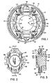
- a wedge brake assembly generally indicated by the numeral 10 includes a drum 12 which is mounted for rotation with a member to be braked, such as a vehicle wheel.
- a fixed support 14 is installed on a non-rotating portion of the vehicle adjacent the drum 12, such as the vehicle axle flange. Attachment of the fixed support 14 to the axle flange can be accomplished, for example, by installing conventional bolts (not shown) in apertures 16 provided in the fixed support.
- a pair of brake shoes 18, 20 are slidably mounted on the fixed support 14 for movement toward and away from the drum 12. The brake shoes 18, 20 are held on the fixed support 14 by conventional hold-down clips 22.
- Each of the brake shoes 13, 20 is of conventional construction having a T-shaped cross-section consisting of a web 24, a shoe table 26 secured to the web 24 and friction material 28 mounted on the shoe table 26.
- the brake shoe 18 has widened, roller-like ends 30, 32 and the brake shoe 20 has similar ends 34, 36.
- a pair of actuator housings 38, 40 are mounted on the fixed support 14 between the ends 30, 34 and 32, 36 of the brake shoes 18 and 20 respectively.
- the actuator housings 38, 40 each contain actuator assemblies of the type shown, for example, in copending U.S. Patent Application Serial No. 345,970 filed February 5, 1982. Since the actuators are fully disclosed in the aforementioned patent application and form no part of the present invention, they will not be further described herein.
- the actuating mechanism does include pistons 42, a pair of which are slidably mounted in each of the actuator housings 38, 40, and are connected to the corresponding ends 30-36 of the brake shoes 18, 20 by mechanism generally indicated by the numeral 44 (see Figure 3).
- the connecting mechanism 44 includes an adjusting screw 50 comprising a threaded shank 52 and a flange 54 which projects radially from the shank 52.
- the shank 52 is provided with screw threads (not shown) which threadedly engage corresponding screw threads (not shown) provided on the inner bore 56 of the piston 42.
- the adjuster screw 50 can be extended from the piston 42 to thereby accomplish adjustment of the brakes by moving the released position of the brake shoes 18, 20 closer to the drum 12 to compensate for wear of the friction material 28. This adjustment is accomplished either automatically by mechanism well known to those skilled in the art, or manually as will hereinafter be described.
- a clip assembly generally indicated by the numeral 58 includes a body portion 60 which extends generally parallel to the side 62 of the flange 54 which faces away from the actuator assembly 38 and toward the brake shoe 20.
- the body portion 60 is provided with an aperture 62 which receives the head 64 of the screw 50.
- a pair of forward facing projections 66, 68 which face toward the brake shoe 20 and away from the side 62 of the flange portion 54, cooperate with the body portion 60 to define a recess which receives the enlarged end 34 of the brake shoe 20.
- the clip 58 further includes a pair of arms 70, 72 which wrap around the periphery of the flange portion 54 and terminate in sections 74, 76 which face the side 78 of the flange 54 opposite the side 62.
- the arm sections 74, 76 are provided with detents 78, 80, which are small rounded projections received in corresponding detents defined by recesses 82 which circumscribe the periphery of the flange portion 54.
- the recesses 82 also function to receive a conventional adjusting tool (not shown) by which the adjusting screw 50 can be rotated, as will hereinafter be described in detail.
- a conventional Belleville spring washer 84 circumscribes the head 64 of the adjusting screw 50.
- the inner edge 86 of the Belleville washer 84 engages the surface 62 on the flange portion 54, and the outer edge 88 of the Belleville washer 84 engages the body portion 60 of the clip 58.
- the Belleville washer is conventional, and acts as a spring which collapses when a predetermined force is applied thereto. In the absence of such force, the Belleville washer 84 resiliently urges the body portion 60 of the clip away from the surface 62.
- the braking mechanism 10 operates as described hereinabove, in which operation of the aforementioned actuation mechanism shown in copending U.S. Patent Application Serial No. 345,970 forces the brake shoes 18, 20 towards the drum 12, thereby effecting a brake application.
- the return springs 46, 48 urge the brake shoes 18, 20 away from the drum 12 toward the position illustrated in Figure 1.
- Manual adjustment of the brakes may be effected by inserting a proper brake adjustment tool into one of the exposed recesses 82 on the periphery of the flange 54.
- the Belleville washer 84 partially collapses and the detents 78, 80 are forced out of their corresponding recesses 82.
- the torque required to turn the adjusting screw 50 in either direction is a function of the strength of the Belleville washer 84, which remains substantially constant.
Landscapes
- Engineering & Computer Science (AREA)
- General Engineering & Computer Science (AREA)
- Mechanical Engineering (AREA)
- Braking Arrangements (AREA)
Applications Claiming Priority (2)
| Application Number | Priority Date | Filing Date | Title |
|---|---|---|---|
| US46257683A | 1983-01-31 | 1983-01-31 | |
| US462576 | 1983-01-31 |
Publications (2)
| Publication Number | Publication Date |
|---|---|
| EP0116501A1 true EP0116501A1 (de) | 1984-08-22 |
| EP0116501B1 EP0116501B1 (de) | 1987-10-07 |
Family
ID=23836945
Family Applications (1)
| Application Number | Title | Priority Date | Filing Date |
|---|---|---|---|
| EP84400198A Expired EP0116501B1 (de) | 1983-01-31 | 1984-01-30 | Bremseinstellschraube und Klammerzusammenbau |
Country Status (8)
| Country | Link |
|---|---|
| EP (1) | EP0116501B1 (de) |
| JP (1) | JPS59144830A (de) |
| AR (1) | AR231574A1 (de) |
| AU (1) | AU2299383A (de) |
| BR (1) | BR8400440A (de) |
| DE (1) | DE3466728D1 (de) |
| ES (1) | ES529290A0 (de) |
| MX (1) | MX157213A (de) |
Cited By (1)
| Publication number | Priority date | Publication date | Assignee | Title |
|---|---|---|---|---|
| FR2570780A1 (fr) * | 1984-09-21 | 1986-03-28 | Perrot Bremse Gmbh Deutsche | Dispositif d'ecartement pour un frein a tambour a machoires interieures |
Families Citing this family (2)
| Publication number | Priority date | Publication date | Assignee | Title |
|---|---|---|---|---|
| DE102017129672B4 (de) * | 2017-12-12 | 2025-05-08 | Knorr-Bremse Systeme für Nutzfahrzeuge GmbH | Scheibenbremse für ein Nutzfahrzeug und Bremsbelagsatz |
| CN115013460B (zh) * | 2022-07-21 | 2023-06-16 | 临沂高新区鸿图电子有限公司 | 一种初始位置可调的直线行程报警机构 |
Citations (2)
| Publication number | Priority date | Publication date | Assignee | Title |
|---|---|---|---|---|
| US3570632A (en) * | 1968-11-12 | 1971-03-16 | Rockwell Standard Co | Brake structure |
| US4270634A (en) * | 1978-11-24 | 1981-06-02 | Akebono Brake Industry Co. Ltd. | Automatic/manual adjuster for drum brake |
Family Cites Families (1)
| Publication number | Priority date | Publication date | Assignee | Title |
|---|---|---|---|---|
| US3797613A (en) * | 1972-10-19 | 1974-03-19 | Rockwell International Corp | Automatic adjuster with limiting device |
-
1983
- 1983-12-30 AU AU22993/83A patent/AU2299383A/en not_active Abandoned
-
1984
- 1984-01-13 MX MX20003684A patent/MX157213A/es unknown
- 1984-01-27 AR AR29555684A patent/AR231574A1/es active
- 1984-01-30 BR BR8400440A patent/BR8400440A/pt unknown
- 1984-01-30 DE DE8484400198T patent/DE3466728D1/de not_active Expired
- 1984-01-30 EP EP84400198A patent/EP0116501B1/de not_active Expired
- 1984-01-30 ES ES529290A patent/ES529290A0/es active Granted
- 1984-01-31 JP JP1454584A patent/JPS59144830A/ja active Pending
Patent Citations (2)
| Publication number | Priority date | Publication date | Assignee | Title |
|---|---|---|---|---|
| US3570632A (en) * | 1968-11-12 | 1971-03-16 | Rockwell Standard Co | Brake structure |
| US4270634A (en) * | 1978-11-24 | 1981-06-02 | Akebono Brake Industry Co. Ltd. | Automatic/manual adjuster for drum brake |
Cited By (1)
| Publication number | Priority date | Publication date | Assignee | Title |
|---|---|---|---|---|
| FR2570780A1 (fr) * | 1984-09-21 | 1986-03-28 | Perrot Bremse Gmbh Deutsche | Dispositif d'ecartement pour un frein a tambour a machoires interieures |
Also Published As
| Publication number | Publication date |
|---|---|
| ES8502522A1 (es) | 1985-01-01 |
| ES529290A0 (es) | 1985-01-01 |
| DE3466728D1 (en) | 1987-11-12 |
| BR8400440A (pt) | 1984-09-04 |
| MX157213A (es) | 1988-01-13 |
| AR231574A1 (es) | 1984-12-28 |
| AU2299383A (en) | 1984-08-02 |
| EP0116501B1 (de) | 1987-10-07 |
| JPS59144830A (ja) | 1984-08-20 |
Similar Documents
| Publication | Publication Date | Title |
|---|---|---|
| US4364455A (en) | Retraction spring for disc brake pads | |
| US3662864A (en) | Disk type brake with split primary shoe | |
| EP1069333B1 (de) | Trommelbremsvorrichtung | |
| US7182182B2 (en) | Drum brake and brake shoe for one such brake | |
| US4476968A (en) | Expanding shoe drum brake | |
| US5860496A (en) | Pin guided push-pull caliper | |
| US7040464B1 (en) | Brake shoe assembly and disc brake assembly including such a brake shoe assembly | |
| JPS5891934A (ja) | デイスクブレ−キ用摩擦パツド組立体 | |
| US3917032A (en) | Single mount and guide pin for a caliper of a disc brake assembly | |
| US6719105B1 (en) | Pad retraction spring for disc brake assembly | |
| US6247561B1 (en) | Disk brake | |
| US5630486A (en) | Mechanical actuation device for drum brake | |
| US3893546A (en) | Disc brake support and caliper mounting | |
| US3232391A (en) | Wheel cylinder, backing plate connection | |
| US6196360B1 (en) | Automatic shoe clearance adjustment device for drum brakes | |
| EP4107405B1 (de) | Bremsbelaghaltesystem, bremsbelag und fahrzeug | |
| GB2036898A (en) | Disc Brakes | |
| EP0116501B1 (de) | Bremseinstellschraube und Klammerzusammenbau | |
| EP3951207B1 (de) | Bremsbelag | |
| EP0143170B1 (de) | Stützungs- und Führungseinrichtung für Scheibenbremsenbremsbacken | |
| US4573557A (en) | Drum brake | |
| US4573249A (en) | Method of manufacturing brake shoe assembly | |
| GB2033987A (en) | Disc brake | |
| US4064978A (en) | Arrangement and method of drum brake spring attachment | |
| US2842229A (en) | Internal expanding brake |
Legal Events
| Date | Code | Title | Description |
|---|---|---|---|
| PUAI | Public reference made under article 153(3) epc to a published international application that has entered the european phase |
Free format text: ORIGINAL CODE: 0009012 |
|
| AK | Designated contracting states |
Designated state(s): DE FR GB IT SE |
|
| 17P | Request for examination filed |
Effective date: 19850117 |
|
| 17Q | First examination report despatched |
Effective date: 19860404 |
|
| RAP1 | Party data changed (applicant data changed or rights of an application transferred) |
Owner name: ALLIED CORPORATION |
|
| ITF | It: translation for a ep patent filed | ||
| GRAA | (expected) grant |
Free format text: ORIGINAL CODE: 0009210 |
|
| AK | Designated contracting states |
Kind code of ref document: B1 Designated state(s): DE FR GB IT SE |
|
| REF | Corresponds to: |
Ref document number: 3466728 Country of ref document: DE Date of ref document: 19871112 |
|
| ET | Fr: translation filed | ||
| PLBE | No opposition filed within time limit |
Free format text: ORIGINAL CODE: 0009261 |
|
| STAA | Information on the status of an ep patent application or granted ep patent |
Free format text: STATUS: NO OPPOSITION FILED WITHIN TIME LIMIT |
|
| 26N | No opposition filed | ||
| PGFP | Annual fee paid to national office [announced via postgrant information from national office to epo] |
Ref country code: SE Payment date: 19900112 Year of fee payment: 7 |
|
| PGFP | Annual fee paid to national office [announced via postgrant information from national office to epo] |
Ref country code: FR Payment date: 19900115 Year of fee payment: 7 |
|
| ITTA | It: last paid annual fee | ||
| PGFP | Annual fee paid to national office [announced via postgrant information from national office to epo] |
Ref country code: GB Payment date: 19900131 Year of fee payment: 7 |
|
| PGFP | Annual fee paid to national office [announced via postgrant information from national office to epo] |
Ref country code: DE Payment date: 19900228 Year of fee payment: 7 |
|
| PG25 | Lapsed in a contracting state [announced via postgrant information from national office to epo] |
Ref country code: GB Effective date: 19910130 |
|
| PG25 | Lapsed in a contracting state [announced via postgrant information from national office to epo] |
Ref country code: SE Effective date: 19910131 |
|
| GBPC | Gb: european patent ceased through non-payment of renewal fee | ||
| PG25 | Lapsed in a contracting state [announced via postgrant information from national office to epo] |
Ref country code: FR Effective date: 19910930 |
|
| PG25 | Lapsed in a contracting state [announced via postgrant information from national office to epo] |
Ref country code: DE Effective date: 19911001 |
|
| REG | Reference to a national code |
Ref country code: FR Ref legal event code: ST |
|
| EUG | Se: european patent has lapsed |
Ref document number: 84400198.2 Effective date: 19910910 |