EP0116859B2 - Procédé et appareil de coupe et de rainurage pour la fabrication de flans pourvus de lignes de pliage - Google Patents
Procédé et appareil de coupe et de rainurage pour la fabrication de flans pourvus de lignes de pliage Download PDFInfo
- Publication number
- EP0116859B2 EP0116859B2 EP84100518A EP84100518A EP0116859B2 EP 0116859 B2 EP0116859 B2 EP 0116859B2 EP 84100518 A EP84100518 A EP 84100518A EP 84100518 A EP84100518 A EP 84100518A EP 0116859 B2 EP0116859 B2 EP 0116859B2
- Authority
- EP
- European Patent Office
- Prior art keywords
- foil
- backing plate
- heated
- heating
- temperature
- Prior art date
- Legal status (The legal status is an assumption and is not a legal conclusion. Google has not performed a legal analysis and makes no representation as to the accuracy of the status listed.)
- Expired - Lifetime
Links
- 238000000034 method Methods 0.000 title claims description 14
- 239000000463 material Substances 0.000 claims description 13
- 238000010438 heat treatment Methods 0.000 claims description 9
- 239000011888 foil Substances 0.000 claims 7
- 238000012856 packing Methods 0.000 claims 1
- 239000002985 plastic film Substances 0.000 description 11
- 229920006255 plastic film Polymers 0.000 description 11
- 239000004020 conductor Substances 0.000 description 2
- 238000004519 manufacturing process Methods 0.000 description 2
- 238000005452 bending Methods 0.000 description 1
- 230000001419 dependent effect Effects 0.000 description 1
- 238000010586 diagram Methods 0.000 description 1
- 230000000694 effects Effects 0.000 description 1
- 230000007613 environmental effect Effects 0.000 description 1
- 239000012212 insulator Substances 0.000 description 1
- 238000004806 packaging method and process Methods 0.000 description 1
- 230000005855 radiation Effects 0.000 description 1
Images

Classifications
-
- B—PERFORMING OPERATIONS; TRANSPORTING
- B29—WORKING OF PLASTICS; WORKING OF SUBSTANCES IN A PLASTIC STATE IN GENERAL
- B29C—SHAPING OR JOINING OF PLASTICS; SHAPING OF MATERIAL IN A PLASTIC STATE, NOT OTHERWISE PROVIDED FOR; AFTER-TREATMENT OF THE SHAPED PRODUCTS, e.g. REPAIRING
- B29C53/00—Shaping by bending, folding, twisting, straightening or flattening; Apparatus therefor
- B29C53/02—Bending or folding
- B29C53/04—Bending or folding of plates or sheets
- B29C53/06—Forming folding lines by pressing or scoring
-
- B—PERFORMING OPERATIONS; TRANSPORTING
- B26—HAND CUTTING TOOLS; CUTTING; SEVERING
- B26D—CUTTING; DETAILS COMMON TO MACHINES FOR PERFORATING, PUNCHING, CUTTING-OUT, STAMPING-OUT OR SEVERING
- B26D3/00—Cutting work characterised by the nature of the cut made; Apparatus therefor
- B26D3/08—Making a superficial cut in the surface of the work without removal of material, e.g. scoring, incising
- B26D3/085—On sheet material
-
- B—PERFORMING OPERATIONS; TRANSPORTING
- B26—HAND CUTTING TOOLS; CUTTING; SEVERING
- B26F—PERFORATING; PUNCHING; CUTTING-OUT; STAMPING-OUT; SEVERING BY MEANS OTHER THAN CUTTING
- B26F1/00—Perforating; Punching; Cutting-out; Stamping-out; Apparatus therefor
- B26F1/38—Cutting-out; Stamping-out
- B26F1/44—Cutters therefor; Dies therefor
-
- B—PERFORMING OPERATIONS; TRANSPORTING
- B26—HAND CUTTING TOOLS; CUTTING; SEVERING
- B26F—PERFORATING; PUNCHING; CUTTING-OUT; STAMPING-OUT; SEVERING BY MEANS OTHER THAN CUTTING
- B26F3/00—Severing by means other than cutting; Apparatus therefor
- B26F3/06—Severing by using heat
- B26F3/08—Severing by using heat with heated members
-
- B—PERFORMING OPERATIONS; TRANSPORTING
- B26—HAND CUTTING TOOLS; CUTTING; SEVERING
- B26F—PERFORATING; PUNCHING; CUTTING-OUT; STAMPING-OUT; SEVERING BY MEANS OTHER THAN CUTTING
- B26F1/00—Perforating; Punching; Cutting-out; Stamping-out; Apparatus therefor
- B26F1/38—Cutting-out; Stamping-out
- B26F1/40—Cutting-out; Stamping-out using a press, e.g. of the ram type
-
- B—PERFORMING OPERATIONS; TRANSPORTING
- B26—HAND CUTTING TOOLS; CUTTING; SEVERING
- B26F—PERFORATING; PUNCHING; CUTTING-OUT; STAMPING-OUT; SEVERING BY MEANS OTHER THAN CUTTING
- B26F1/00—Perforating; Punching; Cutting-out; Stamping-out; Apparatus therefor
- B26F1/38—Cutting-out; Stamping-out
- B26F1/44—Cutters therefor; Dies therefor
- B26F2001/4445—Matrices, female dies, creasing tools
-
- B—PERFORMING OPERATIONS; TRANSPORTING
- B26—HAND CUTTING TOOLS; CUTTING; SEVERING
- B26F—PERFORATING; PUNCHING; CUTTING-OUT; STAMPING-OUT; SEVERING BY MEANS OTHER THAN CUTTING
- B26F1/00—Perforating; Punching; Cutting-out; Stamping-out; Apparatus therefor
- B26F1/38—Cutting-out; Stamping-out
- B26F1/44—Cutters therefor; Dies therefor
- B26F2001/4463—Methods and devices for rule setting, fixation, preparing cutting dies
-
- B—PERFORMING OPERATIONS; TRANSPORTING
- B29—WORKING OF PLASTICS; WORKING OF SUBSTANCES IN A PLASTIC STATE IN GENERAL
- B29C—SHAPING OR JOINING OF PLASTICS; SHAPING OF MATERIAL IN A PLASTIC STATE, NOT OTHERWISE PROVIDED FOR; AFTER-TREATMENT OF THE SHAPED PRODUCTS, e.g. REPAIRING
- B29C37/00—Component parts, details, accessories or auxiliary operations, not covered by group B29C33/00 or B29C35/00
- B29C37/0053—Moulding articles characterised by the shape of the surface, e.g. ribs, high polish
- B29C37/0057—Moulding single grooves or ribs, e.g. tear lines
-
- B—PERFORMING OPERATIONS; TRANSPORTING
- B31—MAKING ARTICLES OF PAPER, CARDBOARD OR MATERIAL WORKED IN A MANNER ANALOGOUS TO PAPER; WORKING PAPER, CARDBOARD OR MATERIAL WORKED IN A MANNER ANALOGOUS TO PAPER
- B31B—MAKING CONTAINERS OF PAPER, CARDBOARD OR MATERIAL WORKED IN A MANNER ANALOGOUS TO PAPER
- B31B50/00—Making rigid or semi-rigid containers, e.g. boxes or cartons
- B31B50/14—Cutting, e.g. perforating, punching, slitting or trimming
- B31B50/20—Cutting sheets or blanks
-
- B—PERFORMING OPERATIONS; TRANSPORTING
- B31—MAKING ARTICLES OF PAPER, CARDBOARD OR MATERIAL WORKED IN A MANNER ANALOGOUS TO PAPER; WORKING PAPER, CARDBOARD OR MATERIAL WORKED IN A MANNER ANALOGOUS TO PAPER
- B31B—MAKING CONTAINERS OF PAPER, CARDBOARD OR MATERIAL WORKED IN A MANNER ANALOGOUS TO PAPER
- B31B50/00—Making rigid or semi-rigid containers, e.g. boxes or cartons
- B31B50/14—Cutting, e.g. perforating, punching, slitting or trimming
- B31B50/20—Cutting sheets or blanks
- B31B50/22—Notching; Trimming edges of flaps
-
- B—PERFORMING OPERATIONS; TRANSPORTING
- B31—MAKING ARTICLES OF PAPER, CARDBOARD OR MATERIAL WORKED IN A MANNER ANALOGOUS TO PAPER; WORKING PAPER, CARDBOARD OR MATERIAL WORKED IN A MANNER ANALOGOUS TO PAPER
- B31B—MAKING CONTAINERS OF PAPER, CARDBOARD OR MATERIAL WORKED IN A MANNER ANALOGOUS TO PAPER
- B31B50/00—Making rigid or semi-rigid containers, e.g. boxes or cartons
- B31B50/25—Surface scoring
- B31B50/252—Surface scoring using presses or dies
Definitions
- the invention relates to a method for producing grooves in plastic films according to the preamble of claim 1.
- the invention further relates to an apparatus for performing this method.
- the grooved plastic film is used for further processing to form a package. Due to the groove formed, the thickness of the plastic film is weakened and can be bent off at the fold edge formed.
- Mechanical erection, folding and folding elements are used in a known manner in the manufacture of the packaging. They can only properly process the grooved plastic film if the grooving has been carried out properly in the desired manner. After bending, the film material has an internal resilience on the groove. In order to keep film parts bent on the grooves in a desired, predetermined direction for further processing, only a certain resilience is desired.
- the temperature of the counterplate must be below the respective softening temperature of the film material lying on it so that it can be shifted in cycles along the counterplate.
- the temperature of the grooved knife on the other hand, can be far above the softening temperature mentioned, since the grooved knife only has a very short dwell time for forming the groove on the plastic film.
- FR-A-2 490143 discloses a relevant method in which the counterplate is kept at a temperature in the range between 35 ° and 50 ° C. On the other hand, the temperature of the creasing knife and its dwell time in the groove formed by it can be controlled.
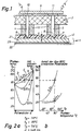
- the device according to FIGS. 1, 3 and 4 has a heated counter plate 1, which is constructed from a thermally conductive cover plate 21, a base plate 22 and an intermediate resistance heating element 23, which is in the form of a film.
- the cover plate 21 had a thickness of 1 mm.
- the plastic film 2 rests on this and is shifted clockwise along it.
- the device has a cutting knife 4 with a cutting edge 6 and also a creasing knife 5. Both the cutting knife 4 and the creasing knife 5 are designed as a strip, so that the creasing knife 5 has an imaginary creasing edge 7 at the lowest point of its lower rounded region. This therefore determines the depth of the groove 8 formed in the film 2.
- the film 2 only has a thickness (a).
- the creasing knife 5 and also the cutting knife 4 are heated, for which purpose a heating plate 9 with transfer plates 10 and 11 is used.
- Cutting knife 4 and creasing knife 5 are surrounded by thermal insulators 13 and are carried by a worktop 3.
- the components 4-7 and 9-11 are moved up and down in relation to the film 2 for creasing and cutting.
- the counter plate 1 is divided into partial areas 26 and 27, which can be heated individually.
- FIG. 3 shows such a partial area 26, which has conductor tracks 30 of the resistance heater, which are provided with connections 31.
- Temperature sensors (not shown) are also partially connected to the counter plate 1. In one embodiment, the connected load of the resistance heater was 6 kW, and this allowed a temperature sensed by the associated sensor to be adjusted by 5 ° C within three seconds. The sensors used had a very fast response time and the heating power of the conductor track 30 was very high.
- Next to the partial area 26 of the counterplate 1 there is an adjacent partial area 27. Each area has its own sensor and can be heated individually.
- the base plate 22 protrudes above the cover plate 21, and the base plate 22 is provided with recesses 32 so that the entire counter plate 1 can be attached to a processing table of a system. Both plates 21 and 22 with the intermediate resistance heater 23 are joined together by means of screws 24 to form the counter plate 1 quantity added. Due to the partial heating of the counter plate 1, a uniform temperature can be achieved over the entire surface of the cover plate 21, since z. B. environmental influences can be compensated. It is understandable that slightly lower temperatures prevail in the edge region of the cover plate 21, that is to say in the region of its ends, than in the central region of the cover plate, for. B. due to air currents and radiation. The plastic film, which is moved at intervals, is also subject to these external influences.
- each plastic film section moved forward in a cycle takes a certain amount of heat away from the counterplate 1. It is clear that the heat removal from the counterplate 1 through the film 2 is cycle-dependent, so that with an increased work cycle the counterplate 1 also has to be heated to keep the counterplate at a certain rate. Maintain temperature.
- the design of the device according to the invention thus serves both to keep the counterplate temperature always at a desired level and to ensure that this desired temperature is uniform over the entire counterplate surface.
- FIGS. 2a and 2b An exemplary embodiment of the method according to the invention is now shown in FIGS. 2a and 2b.
- a plastic film with a thickness of 0.25 mm was grooved.
- the temperature Tp of the counter plate 1 was 75 ° C (this must always be below the respective softening temperature of the film material so that it does not stick).
- the temperature T k of the creasing knife was 110 ° C (this temperature can be significantly above the respective softening temperature of the film material, since the dwell time of the creasing knife on the film material is only a fraction of a second).
- a plastic film was grooved, the softening temperature T s of which was 85 ° C.
- the two curves are entered for dwell times of 0.05 seconds and 0.2 seconds.
- a dwell time of 0.05 seconds the proportion of the film thickness heated above 85 ° C. is 22%, and with a dwell time of 0.2 seconds, the percentage is 75%. So with a dwell time of 0.05 seconds of the creasing knife 5 in the groove 8 of the film 2, 22% of the total film thickness has been softened to the respective softening temperature of 85 ° C. At the dwell time of 0.2 seconds, 75% of the total film thickness has been heated to the softening temperature of 85 ° C.
- the temperature of the counterplate and, if appropriate, the temperature of the creasing knife is selected in order to heat the desired part of the film thickness to or above the respective softening temperature of the film material, the selected temperature of the counterplate then being reduced the inventive design of the device over the entire surface of the cover plate 21 is adhered to, regardless of the number of cycles, d. H. regardless of the cycle of the amount of heat carried away from the counterplate 1 by the plastic film section carried away in each case.
Landscapes
- Engineering & Computer Science (AREA)
- Mechanical Engineering (AREA)
- Life Sciences & Earth Sciences (AREA)
- Forests & Forestry (AREA)
- Shaping Of Tube Ends By Bending Or Straightening (AREA)
Claims (3)
Applications Claiming Priority (2)
| Application Number | Priority Date | Filing Date | Title |
|---|---|---|---|
| CH43283 | 1983-01-26 | ||
| CH432/83 | 1983-01-26 |
Publications (4)
| Publication Number | Publication Date |
|---|---|
| EP0116859A2 EP0116859A2 (fr) | 1984-08-29 |
| EP0116859A3 EP0116859A3 (en) | 1987-12-09 |
| EP0116859B1 EP0116859B1 (fr) | 1989-10-11 |
| EP0116859B2 true EP0116859B2 (fr) | 1993-06-09 |
Family
ID=4186888
Family Applications (1)
| Application Number | Title | Priority Date | Filing Date |
|---|---|---|---|
| EP84100518A Expired - Lifetime EP0116859B2 (fr) | 1983-01-26 | 1984-01-18 | Procédé et appareil de coupe et de rainurage pour la fabrication de flans pourvus de lignes de pliage |
Country Status (2)
| Country | Link |
|---|---|
| EP (1) | EP0116859B2 (fr) |
| DE (1) | DE3480068D1 (fr) |
Families Citing this family (7)
| Publication number | Priority date | Publication date | Assignee | Title |
|---|---|---|---|---|
| GB2299048A (en) * | 1995-03-21 | 1996-09-25 | Cairway Ltd | Sheet forming apparatus |
| GB2314801B (en) * | 1995-05-01 | 1999-03-10 | Korpak Ltd | Cutting and creasing apparatus |
| AU5341296A (en) * | 1995-05-01 | 1996-11-21 | Korpak Limited | Cutting and creasing apparatus |
| DE20116375U1 (de) * | 2001-10-05 | 2002-11-21 | MM Packaging Trier GmbH, 54294 Trier | Stanzvorrichtung zur Herstellung von Faltschachteln und Verpackungszuschnitten |
| CN104972691A (zh) * | 2015-07-06 | 2015-10-14 | 江门市金钩包装机械有限公司 | 一种瓦楞纸压线开槽装置 |
| CN112109378A (zh) * | 2020-09-02 | 2020-12-22 | 宿州市尖端木业有限公司 | 一种木制品模切压痕机 |
| CN121019028B (zh) * | 2025-10-29 | 2026-02-03 | 温州市宏润机械制造有限公司 | 一种用于纸板开槽机的四角压线装置及纸板开槽机 |
Family Cites Families (10)
| Publication number | Priority date | Publication date | Assignee | Title |
|---|---|---|---|---|
| FR822661A (fr) * | 1937-06-04 | 1938-01-05 | Plaques de chauffage électrique pour presses hydrauliques | |
| CH328013A (de) * | 1954-11-24 | 1958-02-28 | Hego Gmbh | Elektrische Heizplatte, insbesondere für Furnierpressen |
| US3379814A (en) * | 1965-03-30 | 1968-04-23 | Mobil Oil Corp | Scoring thermoplastic materials |
| FR1518073A (fr) * | 1966-03-03 | 1968-03-22 | Eastman Kodak Co | Nouveau procédé de fabrication de reliures et reliures obtenues |
| GB1413320A (en) * | 1972-12-29 | 1975-11-12 | Polyfont Sa | Process and apparatus for manufacturing flat plastics-coated objects |
| US4176147A (en) * | 1978-04-21 | 1979-11-27 | Alford Industries, Inc. | Plasticized polyvinyl chloride blanks and cartons |
| DE2851726A1 (de) * | 1978-11-30 | 1980-06-04 | Hans Hagner | Verfahren zum praegen von thermoplastischen folien |
| FR2456604A1 (fr) * | 1979-05-16 | 1980-12-12 | Reine Bernard | Machine automatique pour le marquage a haute frequence de feuilles en matiere plastique |
| DE3015998C2 (de) * | 1980-04-25 | 1983-05-19 | Messerschmitt-Bölkow-Blohm GmbH, 8000 München | Anordnung zur Beheizung großflächiger Laminatformkörper |
| FR2490143A1 (fr) * | 1980-09-17 | 1982-03-19 | Sedat | Procede et machine pour preparer l'ebauche d'une boite par pliage d'une feuille de matiere synthetique. ebauche et boite en resultant |
-
1984
- 1984-01-18 EP EP84100518A patent/EP0116859B2/fr not_active Expired - Lifetime
- 1984-01-18 DE DE8484100518T patent/DE3480068D1/de not_active Expired
Also Published As
| Publication number | Publication date |
|---|---|
| EP0116859B1 (fr) | 1989-10-11 |
| EP0116859A3 (en) | 1987-12-09 |
| DE3480068D1 (en) | 1989-11-16 |
| EP0116859A2 (fr) | 1984-08-29 |
Similar Documents
| Publication | Publication Date | Title |
|---|---|---|
| CH651505A5 (de) | Verfahren zum herstellen eines einbandes fuer ein buch, ein heft oder eine broschuere und vorrichtung zur durchfuehrung des verfahrens. | |
| DE2811450A1 (de) | Verfahren und vorrichtung zum strangpressen | |
| EP0116859B2 (fr) | Procédé et appareil de coupe et de rainurage pour la fabrication de flans pourvus de lignes de pliage | |
| DE2236617C2 (de) | Vorrichtung zum Herstellen einer Faltschachtel aus einer Kunststoff-Folie | |
| DE2336459A1 (de) | Vorrichtung zur herstellung von blattfedern mit trapezfoermigen enden | |
| CH436682A (de) | Verfahren zum Einpressen von Faltlinien in Polyolefinplatten | |
| EP0577094B1 (fr) | Enveloppe protectrice pour cartes de circuits imprimés et procédé pour sa fabrication | |
| DE1479628B2 (de) | Gittermaterial aus einem film einer thermoplastischen masse und vorrichtung zu seiner herstellung | |
| DE2611361C3 (de) | Verfahren und Vorrichtung zur Herstellung von Verbundplatten | |
| DE2107054A1 (de) | Verfahren zur Erzeugung von Trennlinien in einem in der Hitze zerstörbaren Material | |
| DE3686280T2 (de) | Strahlungsheizgeraet mit kurzer reaktionszeit. | |
| DE3435188C2 (de) | Heizeinrichtung zum Erwärmen einer Folie vor deren Warmverformen | |
| DE1291467B (de) | Verfahren zur Zerkleinerung eines in Form einer laenglichen Tafel bzw. Folie vorliegenden Materials zu Granulat | |
| DE2315919A1 (de) | Vorrichtung zum bekleben von platten mit folien | |
| DE1038749B (de) | Vorrichtung zum mehrfachen Abkanten und Verschweissen von Platten aus thermoplastischen Kunststoffen | |
| DE2420477A1 (de) | Verfahren zur bildung einer schweissnaht und vorrichtung zur durchfuehrung des verfahrens | |
| DE2927717C2 (fr) | ||
| DE10350633A1 (de) | Beheizungssystem für eine Verpackungsmaschinenstraße | |
| EP0294507A1 (fr) | Procédé et dispositif pour la production de bandes avec des protubérances, bandes fabriquées selon ce procédé et leur application | |
| DD265610A5 (de) | Verfahren und vorrichtung zum ausbauchen und haerten von glastafeln | |
| DE3018124A1 (de) | Verfahren und vorrichtung zum steuern bzw. regeln eines dielektrischen erwaermungsvorganges | |
| DE3334670A1 (de) | Verfahren zum erwaermen einer folienbahn aus einem thermoplastischem kunststoff mit ausgepraegtem kristallitschmelzpunkt | |
| DE19510121C2 (de) | Verfahren zur Herstellung einer gekrümmten Wandung aus einem streifenförmigen Ausgangsmaterial mit parallelen Seitenkanten und parallelen Längskanten | |
| AT227927B (de) | Verfahren zur Herstellung armierter Platten und Rohre aus thermoplastischem Kunststoff und Vorrichtung zur Durchführung des Verfahrens | |
| DE2713287C2 (de) | Verfahren zum Herstellen von scheibenförmigen Siliciumkörpern |
Legal Events
| Date | Code | Title | Description |
|---|---|---|---|
| PUAI | Public reference made under article 153(3) epc to a published international application that has entered the european phase |
Free format text: ORIGINAL CODE: 0009012 |
|
| AK | Designated contracting states |
Designated state(s): CH DE FR GB LI |
|
| PUAL | Search report despatched |
Free format text: ORIGINAL CODE: 0009013 |
|
| AK | Designated contracting states |
Kind code of ref document: A3 Designated state(s): CH DE FR GB LI |
|
| 17P | Request for examination filed |
Effective date: 19880116 |
|
| 17Q | First examination report despatched |
Effective date: 19880728 |
|
| GRAA | (expected) grant |
Free format text: ORIGINAL CODE: 0009210 |
|
| AK | Designated contracting states |
Kind code of ref document: B1 Designated state(s): CH DE FR GB LI |
|
| GBT | Gb: translation of ep patent filed (gb section 77(6)(a)/1977) | ||
| REF | Corresponds to: |
Ref document number: 3480068 Country of ref document: DE Date of ref document: 19891116 |
|
| ET | Fr: translation filed | ||
| PLBI | Opposition filed |
Free format text: ORIGINAL CODE: 0009260 |
|
| 26 | Opposition filed |
Opponent name: SICHT-PACK HAGNER GMBH Effective date: 19900709 |
|
| PUAH | Patent maintained in amended form |
Free format text: ORIGINAL CODE: 0009272 |
|
| STAA | Information on the status of an ep patent application or granted ep patent |
Free format text: STATUS: PATENT MAINTAINED AS AMENDED |
|
| 27A | Patent maintained in amended form |
Effective date: 19930609 |
|
| AK | Designated contracting states |
Kind code of ref document: B2 Designated state(s): CH DE FR GB LI |
|
| REG | Reference to a national code |
Ref country code: CH Ref legal event code: AEN |
|
| ET3 | Fr: translation filed ** decision concerning opposition | ||
| GBTA | Gb: translation of amended ep patent filed (gb section 77(6)(b)/1977) |
Effective date: 19930707 |
|
| PGFP | Annual fee paid to national office [announced via postgrant information from national office to epo] |
Ref country code: DE Payment date: 19950321 Year of fee payment: 12 |
|
| PG25 | Lapsed in a contracting state [announced via postgrant information from national office to epo] |
Ref country code: DE Effective date: 19961001 |
|
| REG | Reference to a national code |
Ref country code: CH Ref legal event code: AEN Free format text: AUFRECHTERHALTUNG DES PATENTES IN GEAENDERTER FORM |
|
| PGFP | Annual fee paid to national office [announced via postgrant information from national office to epo] |
Ref country code: FR Payment date: 20000119 Year of fee payment: 17 |
|
| PGFP | Annual fee paid to national office [announced via postgrant information from national office to epo] |
Ref country code: GB Payment date: 20000124 Year of fee payment: 17 |
|
| PGFP | Annual fee paid to national office [announced via postgrant information from national office to epo] |
Ref country code: CH Payment date: 20000211 Year of fee payment: 17 |
|
| PG25 | Lapsed in a contracting state [announced via postgrant information from national office to epo] |
Ref country code: GB Free format text: LAPSE BECAUSE OF NON-PAYMENT OF DUE FEES Effective date: 20010118 |
|
| PG25 | Lapsed in a contracting state [announced via postgrant information from national office to epo] |
Ref country code: LI Free format text: LAPSE BECAUSE OF NON-PAYMENT OF DUE FEES Effective date: 20010131 Ref country code: CH Free format text: LAPSE BECAUSE OF NON-PAYMENT OF DUE FEES Effective date: 20010131 |
|
| GBPC | Gb: european patent ceased through non-payment of renewal fee |
Effective date: 20010118 |
|
| REG | Reference to a national code |
Ref country code: CH Ref legal event code: PL |
|
| PG25 | Lapsed in a contracting state [announced via postgrant information from national office to epo] |
Ref country code: FR Free format text: LAPSE BECAUSE OF NON-PAYMENT OF DUE FEES Effective date: 20010928 |
|
| REG | Reference to a national code |
Ref country code: FR Ref legal event code: ST |