EP0116950A1 - Système d'usinage à commande numérique - Google Patents
Système d'usinage à commande numérique Download PDFInfo
- Publication number
- EP0116950A1 EP0116950A1 EP84101563A EP84101563A EP0116950A1 EP 0116950 A1 EP0116950 A1 EP 0116950A1 EP 84101563 A EP84101563 A EP 84101563A EP 84101563 A EP84101563 A EP 84101563A EP 0116950 A1 EP0116950 A1 EP 0116950A1
- Authority
- EP
- European Patent Office
- Prior art keywords
- machining
- turrets
- operations
- display
- lathe
- Prior art date
- Legal status (The legal status is an assumption and is not a legal conclusion. Google has not performed a legal analysis and makes no representation as to the accuracy of the status listed.)
- Granted
Links
Images



Classifications
-
- G—PHYSICS
- G05—CONTROLLING; REGULATING
- G05B—CONTROL OR REGULATING SYSTEMS IN GENERAL; FUNCTIONAL ELEMENTS OF SUCH SYSTEMS; MONITORING OR TESTING ARRANGEMENTS FOR SUCH SYSTEMS OR ELEMENTS
- G05B19/00—Program-control systems
- G05B19/02—Program-control systems electric
- G05B19/18—Numerical control [NC], i.e. automatically operating machines, in particular machine tools, e.g. in a manufacturing environment, so as to execute positioning, movement or co-ordinated operations by means of program data in numerical form
- G05B19/4093—Numerical control [NC], i.e. automatically operating machines, in particular machine tools, e.g. in a manufacturing environment, so as to execute positioning, movement or co-ordinated operations by means of program data in numerical form characterised by part programming, e.g. entry of geometrical information as taken from a technical drawing, combining this with machining and material information to obtain control information, named part program, for the NC machine
- G05B19/40937—Numerical control [NC], i.e. automatically operating machines, in particular machine tools, e.g. in a manufacturing environment, so as to execute positioning, movement or co-ordinated operations by means of program data in numerical form characterised by part programming, e.g. entry of geometrical information as taken from a technical drawing, combining this with machining and material information to obtain control information, named part program, for the NC machine concerning programming of machining or material parameters, pocket machining
-
- G—PHYSICS
- G05—CONTROLLING; REGULATING
- G05B—CONTROL OR REGULATING SYSTEMS IN GENERAL; FUNCTIONAL ELEMENTS OF SUCH SYSTEMS; MONITORING OR TESTING ARRANGEMENTS FOR SUCH SYSTEMS OR ELEMENTS
- G05B2219/00—Program-control systems
- G05B2219/30—Nc systems
- G05B2219/35—Nc in input of data, input till input file format
- G05B2219/35431—Interactive
-
- G—PHYSICS
- G05—CONTROLLING; REGULATING
- G05B—CONTROL OR REGULATING SYSTEMS IN GENERAL; FUNCTIONAL ELEMENTS OF SUCH SYSTEMS; MONITORING OR TESTING ARRANGEMENTS FOR SUCH SYSTEMS OR ELEMENTS
- G05B2219/00—Program-control systems
- G05B2219/30—Nc systems
- G05B2219/36—Nc in input of data, input key till input tape
- G05B2219/36306—Table correlation different turrets, slides and possible simultaneous operations
-
- G—PHYSICS
- G05—CONTROLLING; REGULATING
- G05B—CONTROL OR REGULATING SYSTEMS IN GENERAL; FUNCTIONAL ELEMENTS OF SUCH SYSTEMS; MONITORING OR TESTING ARRANGEMENTS FOR SUCH SYSTEMS OR ELEMENTS
- G05B2219/00—Program-control systems
- G05B2219/30—Nc systems
- G05B2219/50—Machine tool, machine tool null till machine tool work handling
- G05B2219/50001—Multislides, multispindles with multitool turret for each
-
- G—PHYSICS
- G05—CONTROLLING; REGULATING
- G05B—CONTROL OR REGULATING SYSTEMS IN GENERAL; FUNCTIONAL ELEMENTS OF SUCH SYSTEMS; MONITORING OR TESTING ARRANGEMENTS FOR SUCH SYSTEMS OR ELEMENTS
- G05B2219/00—Program-control systems
- G05B2219/30—Nc systems
- G05B2219/50—Machine tool, machine tool null till machine tool work handling
- G05B2219/50015—Multi cutting, twin tools contact at same time workpiece, balance cutting
-
- Y—GENERAL TAGGING OF NEW TECHNOLOGICAL DEVELOPMENTS; GENERAL TAGGING OF CROSS-SECTIONAL TECHNOLOGIES SPANNING OVER SEVERAL SECTIONS OF THE IPC; TECHNICAL SUBJECTS COVERED BY FORMER USPC CROSS-REFERENCE ART COLLECTIONS [XRACs] AND DIGESTS
- Y02—TECHNOLOGIES OR APPLICATIONS FOR MITIGATION OR ADAPTATION AGAINST CLIMATE CHANGE
- Y02P—CLIMATE CHANGE MITIGATION TECHNOLOGIES IN THE PRODUCTION OR PROCESSING OF GOODS
- Y02P90/00—Enabling technologies with a potential contribution to greenhouse gas [GHG] emissions mitigation
- Y02P90/02—Total factory control, e.g. smart factories, flexible manufacturing systems [FMS] or integrated manufacturing systems [IMS]
-
- Y—GENERAL TAGGING OF NEW TECHNOLOGICAL DEVELOPMENTS; GENERAL TAGGING OF CROSS-SECTIONAL TECHNOLOGIES SPANNING OVER SEVERAL SECTIONS OF THE IPC; TECHNICAL SUBJECTS COVERED BY FORMER USPC CROSS-REFERENCE ART COLLECTIONS [XRACs] AND DIGESTS
- Y10—TECHNICAL SUBJECTS COVERED BY FORMER USPC
- Y10T—TECHNICAL SUBJECTS COVERED BY FORMER US CLASSIFICATION
- Y10T82/00—Turning
- Y10T82/25—Lathe
- Y10T82/2531—Carriage feed
- Y10T82/2541—Slide rest
- Y10T82/2543—Multiple tool support
Definitions
- the present invention relates to an NC (numerically controlled) machining system.
- a machining head may be controlled by an NC control device to machine a workpiece to a desired configuration.
- a workpiece In a conventional NC machining system, the position of a tool relative to a workpiece is controlled by numerical information specifying the position of the tool. This numerical data is provided by an NC control system. With such a system, a workpiece can be machined to a complex shape with a high accuracy and at a high rate, thereby yielding a high productivity.
- the invention provides an NC machining system in which a memory is provided for storing combinations of machining instructions for operating plural machining tools such as rotary tools.
- the contents of this memory are displayed on the display device of the system, whereby machining conditions can readily be altered, thereby shortening the time required for performing composite machining operations.
- An NC machining system is constituted, as shown in Figure 1 of the accompanying drawings, by an NC control device 20 which operates upon numerical information inputted by a terminal 10, and an NC machining device 30 which is controlled by the numerical values provided by the NC control device 20.
- the NC control device 20 includes an input section 21 through which externally supplied instructions are inputted, a computing section 22 for operating upon the instructions received via the input section 21, a memory section 23 for storing results of operations performed by the computing section 22, a control section 24 for controlling the operation of the computing section 22, an output section 25 for sending computed values produced by the computing section 22 to the NC machining device 30, and a display section 26, which includes a keyboard, for inputting and displaying the data, including the data received via the input section 21, the outputs produced by the output section 25, and the contents of the memory section 23.
- the machining device 30 includes a tool 31 attached to a tool holder 32, which is in turn attached to a chuck of a spindle 33.
- the spindle 33 is rotated by a spindle motor drive 34, which is in turn controlled by a signal provided by the output section 25 of the NC control device 20.
- a workpiece 40 is fixed to a table 35 of the machining device 30 by a jig or the like.
- a lead screw 36 is provided for moving the table 35 in the direction of the X axis.
- the screw 36 is driven along the X axis by a motor 38 through a gear box 37.
- the motor 38 is controlled by a signal produced from the output section 25 of the NC control device 20.
- lead screws, motors and gear boxes are provided for moving the table 35 in the Y and Z directions in response to signals produced by the output section 25 of the NC control device 20.
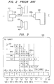
- FIG. 2 An example of a lathe is shown in outline form in Figure 2 of the accompanying drawings.
- a cylindrical workpiece 110 is held at one end by a chuck 101, the latter being rotated around the Z axis.
- the other end of the workpiece 110 is supported by the tip 102a of a tail stock 102.
- Rotating cutting tools 105 and 106 are provided for machining the workpiece 110.
- the tools 105 and 106 are fixed to first and second turrets 103 and 104, respectively.
- the first and second turrets 103 and 104 are moved in the direction of the Z axis.
- Figure 3 shows a display which is produced when the present invention is employed. As indicated in Figure 3, combinations of operations to be performed by the first and second turrets 103 and 104 are displayed on a display 120. On the display 120, a menu display section 121 is reserved for displaying indications of nine different menus 121-1 to 121-9. Below the display 120, menu selection switches 122-1 to 122-9 are provided for selecting among the menus 121-1 to 121-9, respectively. These switches form part of the input terminal 10.
- THR represents the case in which threads are to be cut
- GRV GROOVE
- DRL indicates drilling
- TAP TAPPING
- OUT represents an outer diameter
- IN represents an inner diameter
- FCE FACE
- Combinations of operations by the first and second turrets 103 and 104 are displayed in a matrix as shown in Figure 3.
- the operator can observe the various combinations of operations of the first and second turrets 103 and 104, and hence fully understand that it is possible for drilling with the first turret 103 and grooving with the second turret 104 to be carried out simultaneously.
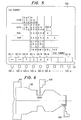
- the operator suitably actuates the menu switches 122-1, 122-2, 122-3 and 122-4 corresponding, respectively, to a left correction shifting menu 121-1, a right correction shifting menu 121-2, an upward correction shifting menu 121-3, and a downward correction shifting menu 121-4, thereby to move a cursor 123 from the initial position indicated in Figure 3 to a position such as position 200-1 indicated in Figure 4.
- the operator actuates the menu selection switch 122-5, corresponding to the menu 121-5, thereby causing the display of a mark "0" at the position 200-1, as, indicated in Figure 5, which indicates that drilling by the first turret is to take place simultaneously with grooving by the second turret on the front end surface.
- the display of Figure 3 indicates to the operator by means of the mark "X" that simultaneous grooving by the first turret 103 and thread-cutting by the second turret 104 cannot be achieved on any surfaces.
- the oeprator may suitably actuate the menu selection switches to effect such simultaneous working and to cause the display of the mark "0" in place of the mark "X" in the same manner as discussed above.
- Step 7 is a flowchart used for explaining the operation of the above-described embodiment of the present invention.
- reference numerals 1 to 12 designate various steps.
- Step 1 the start of operations is effected.
- Step 2 a particular "work combination" image picture is selected, and then displayed in the Step 3.
- Step 4 the cursor is shifted to a desired position in Step 5.
- the desired combination of operations by the first and second turrets 103 and 104 can be performed as determined in Step 6
- the content of the memory is written in Step 9 upon the depression of the menu selection switch corresponding to the menu marked with "0" in Step 7..
- the mark "0" is displayed at the desired position on the display in Step 8, thereby effecting the desired combination of operations.
- Step 6 content of the memory related to the desired working combination is written upon the depression of the menu selection switch corresponding to the menu marked with "X", that is, a switch 122-6, in Step 10.
- the mark "X" is displayed at the desired position on the display 120 in Step 11, thereby indicating that the desired combination of the operations cannot be performed. If no setting operation is required in Step 4; the setting operation is terminated in Step 12. These operations can be repeated.
- time-successive display of the various combinations of operations of the three turrets can be performed.
- a lathe has been considered as an example, the present invention is not limited to a lathe, but more generally applicable to any other NC machining system.
- the computing section 22 e.g. a microprocessor
- the control section 24 e.g. a ROM storing an operating program for the microprocessor
Landscapes
- Physics & Mathematics (AREA)
- Engineering & Computer Science (AREA)
- Geometry (AREA)
- Human Computer Interaction (AREA)
- Manufacturing & Machinery (AREA)
- General Physics & Mathematics (AREA)
- Automation & Control Theory (AREA)
- Numerical Control (AREA)
Applications Claiming Priority (2)
| Application Number | Priority Date | Filing Date | Title |
|---|---|---|---|
| JP23984/83 | 1983-02-16 | ||
| JP58023984A JPS59152042A (ja) | 1983-02-16 | 1983-02-16 | 数値制御加工方式 |
Publications (2)
| Publication Number | Publication Date |
|---|---|
| EP0116950A1 true EP0116950A1 (fr) | 1984-08-29 |
| EP0116950B1 EP0116950B1 (fr) | 1987-11-04 |
Family
ID=12125830
Family Applications (1)
| Application Number | Title | Priority Date | Filing Date |
|---|---|---|---|
| EP84101563A Expired EP0116950B1 (fr) | 1983-02-16 | 1984-02-16 | Système d'usinage à commande numérique |
Country Status (4)
| Country | Link |
|---|---|
| US (1) | US4700313A (fr) |
| EP (1) | EP0116950B1 (fr) |
| JP (1) | JPS59152042A (fr) |
| DE (1) | DE3467260D1 (fr) |
Cited By (5)
| Publication number | Priority date | Publication date | Assignee | Title |
|---|---|---|---|---|
| EP0154028A3 (fr) * | 1983-12-23 | 1987-05-20 | Mitsubishi Denki Kabushiki Kaisha | Méthode de travail pour machine-outil à commande numérique |
| GB2187308A (en) * | 1986-02-27 | 1987-09-03 | Mitsubishi Electric Corp | An operation program checking method for a numerical control device |
| GB2192471A (en) * | 1986-07-10 | 1988-01-13 | Unilever Plc | Compiling control program |
| EP0303705A4 (fr) * | 1987-02-20 | 1990-01-24 | Fanuc Ltd | Procede d'introduction d'informations relatives a un profil. |
| EP0247204B1 (fr) * | 1985-11-20 | 1993-03-10 | Fanuc Ltd. | Dispositif de programmation interactive |
Families Citing this family (16)
| Publication number | Priority date | Publication date | Assignee | Title |
|---|---|---|---|---|
| JPS60258606A (ja) * | 1984-06-05 | 1985-12-20 | Fanuc Ltd | 自動プログラミング方式 |
| JPS61265240A (ja) * | 1985-05-18 | 1986-11-25 | Fanuc Ltd | 4軸旋盤用のncプログラム編集方法 |
| US5157595A (en) * | 1985-07-19 | 1992-10-20 | El Paso Technologies, Company | Distributed logic control system and method |
| JPS62136340A (ja) * | 1985-12-10 | 1987-06-19 | Fanuc Ltd | 4軸旋盤用ncプログラムの修正方法 |
| JPS62199338A (ja) * | 1986-02-27 | 1987-09-03 | Fanuc Ltd | 工具衝突自動防止方法 |
| JPS62236650A (ja) * | 1986-04-01 | 1987-10-16 | Fanuc Ltd | 4軸旋盤のncプログラム作成方法 |
| KR910002317B1 (ko) * | 1986-07-04 | 1991-04-11 | 미쓰비시 뎅끼 가부시끼가이샤 | 수치제어장치 |
| US4979121A (en) * | 1987-09-25 | 1990-12-18 | Yamazaki Mazak Corporation | Control method and apparatus for controlling machining operations in a machine tool having a plurality of coordinate systems |
| JPH0242510A (ja) * | 1988-08-03 | 1990-02-13 | Fanuc Ltd | 加工情報表示方式 |
| US5293106A (en) * | 1989-12-11 | 1994-03-08 | Murata Kikai Kabushiki Kaisha | Program reviewing device in numerical control processing apparatus |
| US5007123A (en) * | 1990-07-05 | 1991-04-16 | Comfortex, Inc. | Flexible covering for reducing moisture/vapor/bacteria transmission |
| US5103558A (en) * | 1990-08-24 | 1992-04-14 | Tecumseh Products Company | Method and apparatus for machining scroll wraps |
| JP3218530B2 (ja) * | 1994-06-30 | 2001-10-15 | 富士通株式会社 | 数値制御加工方法及び数値制御加工システム |
| US7318767B2 (en) * | 2004-10-05 | 2008-01-15 | Ruger, Barthelt & Abel | Device and method for machine control |
| DE102009037165A1 (de) * | 2009-08-03 | 2011-02-17 | Stama Maschinenfabrik Gmbh | Vorrichtung zur Steuerung einer Werkzeugmaschine |
| WO2014116696A2 (fr) | 2013-01-22 | 2014-07-31 | Oc10, Llc | Procédé et appareil pour relier une ligne de pêche à un autre élément de pêche, pour régler la flottabilité d'éléments de pêche et pour couper une ligne de pêche |
Citations (3)
| Publication number | Priority date | Publication date | Assignee | Title |
|---|---|---|---|---|
| DE2644596A1 (de) * | 1975-10-06 | 1977-04-07 | Philips Nv | Numerische steuerung fuer eine mehrwerkzeugmaschine |
| FR2523328A1 (fr) * | 1982-03-11 | 1983-09-16 | Yamazaki Mach Works | Procede de commande d'usinage pour un tour a commande numerique quadriaxiale |
| GB2118328A (en) * | 1982-03-30 | 1983-10-26 | Yamazaki Mach Works | Method of controlling operation of two tool rests of a quadriaxial numerical control lathe |
Family Cites Families (7)
| Publication number | Priority date | Publication date | Assignee | Title |
|---|---|---|---|---|
| DE2401083C2 (de) * | 1974-01-10 | 1975-08-14 | Index-Werke Kg Hahn & Tessky, 7300 Esslingen | Steuereinrichtung^zum Steuern eines entsprechend einem Programm in ausgewählte Winkelstellungen schwenkbaren und feststellbaren Werkzeugträgers einer Werkzeugmaschine |
| US4033206A (en) * | 1974-07-11 | 1977-07-05 | Daihatsu Motor Co., Ltd. | Numerically controlled machine tool |
| US4312105A (en) * | 1978-06-28 | 1982-01-26 | Hardinge Brothers, Inc. | Programmable turret-type machine tool |
| JPS5727306A (en) * | 1980-07-24 | 1982-02-13 | Fanuc Ltd | Numerical control system |
| US4472770A (en) * | 1981-06-22 | 1984-09-18 | Li Chou H | Self-optimizing method and machine |
| US4428055A (en) * | 1981-08-18 | 1984-01-24 | General Electric Company | Tool touch probe system and method of precision machining |
| JPS5882647A (ja) * | 1981-11-05 | 1983-05-18 | Yamazaki Mazak Corp | マシニングセンタにおけるマガジンポケツトの割付け制御方法 |
-
1983
- 1983-02-16 JP JP58023984A patent/JPS59152042A/ja active Granted
-
1984
- 1984-02-16 DE DE8484101563T patent/DE3467260D1/de not_active Expired
- 1984-02-16 EP EP84101563A patent/EP0116950B1/fr not_active Expired
-
1987
- 1987-02-02 US US07/011,346 patent/US4700313A/en not_active Expired - Lifetime
Patent Citations (3)
| Publication number | Priority date | Publication date | Assignee | Title |
|---|---|---|---|---|
| DE2644596A1 (de) * | 1975-10-06 | 1977-04-07 | Philips Nv | Numerische steuerung fuer eine mehrwerkzeugmaschine |
| FR2523328A1 (fr) * | 1982-03-11 | 1983-09-16 | Yamazaki Mach Works | Procede de commande d'usinage pour un tour a commande numerique quadriaxiale |
| GB2118328A (en) * | 1982-03-30 | 1983-10-26 | Yamazaki Mach Works | Method of controlling operation of two tool rests of a quadriaxial numerical control lathe |
Cited By (6)
| Publication number | Priority date | Publication date | Assignee | Title |
|---|---|---|---|---|
| EP0154028A3 (fr) * | 1983-12-23 | 1987-05-20 | Mitsubishi Denki Kabushiki Kaisha | Méthode de travail pour machine-outil à commande numérique |
| EP0247204B1 (fr) * | 1985-11-20 | 1993-03-10 | Fanuc Ltd. | Dispositif de programmation interactive |
| GB2187308A (en) * | 1986-02-27 | 1987-09-03 | Mitsubishi Electric Corp | An operation program checking method for a numerical control device |
| GB2187308B (en) * | 1986-02-27 | 1990-03-07 | Mitsubishi Electric Corp | Operation program checking method for a numerical control device |
| GB2192471A (en) * | 1986-07-10 | 1988-01-13 | Unilever Plc | Compiling control program |
| EP0303705A4 (fr) * | 1987-02-20 | 1990-01-24 | Fanuc Ltd | Procede d'introduction d'informations relatives a un profil. |
Also Published As
| Publication number | Publication date |
|---|---|
| JPH0321298B2 (fr) | 1991-03-22 |
| JPS59152042A (ja) | 1984-08-30 |
| DE3467260D1 (en) | 1987-12-10 |
| EP0116950B1 (fr) | 1987-11-04 |
| US4700313A (en) | 1987-10-13 |
Similar Documents
| Publication | Publication Date | Title |
|---|---|---|
| EP0116950B1 (fr) | Système d'usinage à commande numérique | |
| EP0213531B1 (fr) | Système automatique de programmation pour un programme numérique utilisé dans une machine-outil d'usinage | |
| US4604705A (en) | Numerical control machining method and system therefor | |
| US4521860A (en) | Methods of entering machining information and display therefor in a numerically controlled machine tool | |
| EP0223857B1 (fr) | Procede de compilation de programmes de commande numerique pour un tour a quatre axes | |
| KR900003124B1 (ko) | 수치제어장치 | |
| US4739488A (en) | Machine tool with tool selection and work sequence determination | |
| US5127140A (en) | Numerically-controlled lathe, numerically-controlled device therefor and processing procedure thereby | |
| US4558419A (en) | Method of judging and controlling simultaneous machining in a quadriaxial numerical control lathe | |
| KR850000328B1 (ko) | 수치 제어방법 | |
| US5315503A (en) | Numerical control apparatus having a teaching function and a method of teaching a machining program thereby | |
| JPH0321299B2 (fr) | ||
| US5327350A (en) | Interactive type numerical control apparatus and method thereof | |
| US4571670A (en) | NC Programming Apparatus | |
| US4922440A (en) | Tool profile automatic graphic display system | |
| KR870001582B1 (ko) | 수치 제어 가공 방식 | |
| US5538369A (en) | Machine tool with tapping function | |
| KR880001305B1 (ko) | 수치 제어 가공 방법 | |
| EP0935179A1 (fr) | Unite de commande numerique possedant une fonction apprentissage/relecture | |
| JPS61257740A (ja) | 工具決定方式 | |
| JPH08112737A (ja) | Nc旋盤の加工プログラム表示方法 | |
| US5270940A (en) | Contour configuration machining method | |
| JPS63196906A (ja) | 旋盤用プログラミング装置 | |
| KR920007244Y1 (ko) | 공작기계 | |
| EP0397884B1 (fr) | Systeme d'usinage de formes profilees |
Legal Events
| Date | Code | Title | Description |
|---|---|---|---|
| PUAI | Public reference made under article 153(3) epc to a published international application that has entered the european phase |
Free format text: ORIGINAL CODE: 0009012 |
|
| AK | Designated contracting states |
Designated state(s): DE FR GB |
|
| 17P | Request for examination filed |
Effective date: 19850227 |
|
| 17Q | First examination report despatched |
Effective date: 19870130 |
|
| GRAA | (expected) grant |
Free format text: ORIGINAL CODE: 0009210 |
|
| AK | Designated contracting states |
Kind code of ref document: B1 Designated state(s): DE FR GB |
|
| REF | Corresponds to: |
Ref document number: 3467260 Country of ref document: DE Date of ref document: 19871210 |
|
| ET | Fr: translation filed | ||
| PLBE | No opposition filed within time limit |
Free format text: ORIGINAL CODE: 0009261 |
|
| STAA | Information on the status of an ep patent application or granted ep patent |
Free format text: STATUS: NO OPPOSITION FILED WITHIN TIME LIMIT |
|
| 26N | No opposition filed | ||
| PGFP | Annual fee paid to national office [announced via postgrant information from national office to epo] |
Ref country code: FR Payment date: 19930209 Year of fee payment: 10 |
|
| PG25 | Lapsed in a contracting state [announced via postgrant information from national office to epo] |
Ref country code: FR Effective date: 19941031 |
|
| REG | Reference to a national code |
Ref country code: FR Ref legal event code: ST |
|
| REG | Reference to a national code |
Ref country code: GB Ref legal event code: 746 Effective date: 19951107 |
|
| PGFP | Annual fee paid to national office [announced via postgrant information from national office to epo] |
Ref country code: GB Payment date: 19990218 Year of fee payment: 16 |
|
| PGFP | Annual fee paid to national office [announced via postgrant information from national office to epo] |
Ref country code: DE Payment date: 19991231 Year of fee payment: 17 |
|
| PG25 | Lapsed in a contracting state [announced via postgrant information from national office to epo] |
Ref country code: GB Free format text: LAPSE BECAUSE OF NON-PAYMENT OF DUE FEES Effective date: 20000216 |
|
| GBPC | Gb: european patent ceased through non-payment of renewal fee |
Effective date: 20000216 |
|
| PG25 | Lapsed in a contracting state [announced via postgrant information from national office to epo] |
Ref country code: DE Free format text: LAPSE BECAUSE OF NON-PAYMENT OF DUE FEES Effective date: 20011201 |