EP0117006B1 - Vorrichtung zur automatischen Probenübertragung - Google Patents
Vorrichtung zur automatischen Probenübertragung Download PDFInfo
- Publication number
- EP0117006B1 EP0117006B1 EP84200209A EP84200209A EP0117006B1 EP 0117006 B1 EP0117006 B1 EP 0117006B1 EP 84200209 A EP84200209 A EP 84200209A EP 84200209 A EP84200209 A EP 84200209A EP 0117006 B1 EP0117006 B1 EP 0117006B1
- Authority
- EP
- European Patent Office
- Prior art keywords
- receptacle
- sample
- vacuum
- air cylinder
- samples
- Prior art date
- Legal status (The legal status is an assumption and is not a legal conclusion. Google has not performed a legal analysis and makes no representation as to the accuracy of the status listed.)
- Expired
Links
- 238000012546 transfer Methods 0.000 claims abstract description 28
- 239000000463 material Substances 0.000 claims description 16
- 239000007789 gas Substances 0.000 claims description 15
- 238000000113 differential scanning calorimetry Methods 0.000 claims description 6
- 125000004122 cyclic group Chemical group 0.000 claims description 4
- 230000009897 systematic effect Effects 0.000 claims description 4
- 230000004913 activation Effects 0.000 claims description 2
- 238000002076 thermal analysis method Methods 0.000 claims description 2
- 238000011156 evaluation Methods 0.000 abstract description 5
- 239000000523 sample Substances 0.000 description 77
- 230000001681 protective effect Effects 0.000 description 19
- 238000000034 method Methods 0.000 description 9
- 238000012360 testing method Methods 0.000 description 5
- 239000012925 reference material Substances 0.000 description 3
- 238000013461 design Methods 0.000 description 2
- 238000010926 purge Methods 0.000 description 2
- 238000004458 analytical method Methods 0.000 description 1
- 238000004320 controlled atmosphere Methods 0.000 description 1
- 230000007613 environmental effect Effects 0.000 description 1
- 239000012530 fluid Substances 0.000 description 1
- 238000001864 heat-flux differential scanning calorimetry Methods 0.000 description 1
- 230000000737 periodic effect Effects 0.000 description 1
- 230000035699 permeability Effects 0.000 description 1
- 238000002440 power-compensation differential scanning calorimetry Methods 0.000 description 1
- 239000012857 radioactive material Substances 0.000 description 1
- 239000000126 substance Substances 0.000 description 1
Images


Classifications
-
- G—PHYSICS
- G01—MEASURING; TESTING
- G01N—INVESTIGATING OR ANALYSING MATERIALS BY DETERMINING THEIR CHEMICAL OR PHYSICAL PROPERTIES
- G01N35/00—Automatic analysis not limited to methods or materials provided for in any single one of groups G01N1/00 - G01N33/00; Handling materials therefor
- G01N35/0099—Automatic analysis not limited to methods or materials provided for in any single one of groups G01N1/00 - G01N33/00; Handling materials therefor comprising robots or similar manipulators
Definitions
- the present invention relates to a differential scanning calorimetry apparatus.
- a differential scanning calorimeter is commonly employed in a method for thermally analyzing a material.
- DSC analysis the difference in energy fed into a test material and a reference material are measured as a function of temperature, while the test material and the reference material are subjected, in an environmental (measuring) cell, to a controlled temperature program.
- a relatively small, encapsulated sample of the test material is placed in the measuring cell containing a sample of the reference material, and the measuring cell is then covered with a lid having a passageway to allow the escape of gas from the measuring cell.
- one or more cover means comprising thermal sleeves and/or protective hoods are generally placed over the measuring cell.
- the insulating sleeve(s) and/or protective hood(s) are removed from the measuring cell and a new, encapsulated sample to be tested exchanged for the previously tested sample of the test material.
- the present invention provides a differential scanning calorimetry apparatus comprising means for automatically handling in a cyclic order of operations a plurality of samples on an individual basis, said means comprising a sample holder capable of holding a plurality of samples, first transfer means, comprising first vacuum means to move during each cycle of operation, a sample from the sample holder to a receptacle for the sample, and to remove the tested sample from the receptacle, wherein the first transfer means and the sample holder cooperate in such a manner that a new sample of untested material is transferred from the sample holder to the receptacle and a tested sample is removed from the receptacle during each cycle of operation, wherein the sample holder contains samples destined for differential scanning calorimetry which are provided to the first transfer means in a systematic order, the first transfer means comprises a first, vertical air cylinder which carries at its lower end the first vacuum means to remove and to place said samples, the receptacle comprises a removable cover means and provides for thermal
- DE-B-2,353,793 discloses an apparatus for automatically handling, in a cyclic order of operation, a plurality of samples on an individual basis.
- the apparatus comprises first transfer means including vacuum means to move a sample, in the form of a tablet, from a sample holder to a receptacle.
- This publication does not provide an apparatus for DSC wherein the samples are delivered to the first transfer means in a systematic order and also does not describe cover means for the receptacle nor transfer means for such cover means.
- EP-A-3936 discloses an apparatus for automatically handling, in a cyclic order of operation, a plurality of samples on an individual basis.
- This apparatus comprises, in addition to first transfer means, second transfer means to remove and replace a cover means from respectively on a receptacle.
- the apparatus according to this publication is designed to transport, to weigh and to pour away a fluid sample in a receptacle with a cover.
- the samples consist of quite heavy dangerous chemical or radioactive material, which have to be handled very carefully.
- the publication therefore does not disclose a DSC apparatus with its inherent problems because of the small dimensions of the samples and moreover does not describe in what way the samples are placed in the receptacle.
- the second transfer means comprises a second vacuum means.
- a preferred means for covering the receptacle is designed so that gases can freely pass to or from the receptacle but a vacuum can effectively be applied to the cover.
- a preferred cover means for the receptacle comprises a disk or sheet having one or more perforations or passages therein which allow the flow of gas from one surface of the disk or sheet to the opposite surface and a continuous disk or sheet which allows essentially no gas to flow therethrqugh.
- the perforated disk or sheet and the continuous disk or sheet are interconnected by a conduit having one or more perforations or passages such that gas passing through the perforated disk or sheet subsequently passes from the conduit through said perforations or passages.
- the apparatus of this invention is unique in that it provides an effective and economical means for automatically transferring, in a systematic order, the relatively small, encapsulated samples used for DSC analyses. Moreover, the complexity of the equipment required to provide such automatic sample transfer is surprisingly small. For example, the lifting of the relatively small encapsulated samples as well as the comparatively larger and heavier cover means, insulating sleeve and protective hood for subsequent movement can be accomplished using one vacuum, thereby requiring a single source of vacuum. In addition, the movement, i.e. the removal and replacement, of the small, encapsulated sample and the cover means, insulating sleeve and protective hood can be conducted using air-driven pistons and a single source of compressed air.
- the apparatus of the present invention is particularly useful for automatically handling experimental samples in conjunction with conventional DSC type equipment, including both the powercompensation DSC and the heat flux DSC, thereby allowing continuous and unattended evaluation of a plurality of samples over an extended period.
- Fig. 1 which represents an embodiment of the present invention, depicts a differential scanning calorimeter cell 92 having a support 1 and a receptacle 2.
- Cylinder 3 has a slidable piston or rod 5 connected to a mdvable support 6.
- Movable support 6 supports a first air cylinder 7.
- First air cylinder 7 is connected to the source of air by means of lines 62a and 62b.
- a vacuum nozzle 9 is connected to cylinder 7 by a slidable piston or rod 8.
- vacuum nozzle 9 is connected to a source of vacuum (not shown) by means of line 51.
- the sample table 10 is rotably mounted on a base 11 by means of a rotating rod or bearing 21.
- the table 10 and nozzle 9 are positioned so that vacuum nozzle 9 can pick up a sample from table 10 and transport it to the receptacle 2 of the DSC unit.
- the sample handling apparatus depicted in Fig. 1 further comprises a second transfer means 91 having a third air-driven cylinder 12 supported by a stand 13 and connected to an air source by means of lines 64a and 64b.
- a slidable piston or rod 22 which supports a fourth air-driven cylinder 14.
- Cylinder 14 is connected to an air source by means of lines 63a and 63b.
- a slidable piston or rod 15 a vacuum cup 16 connected thereto. Vacuum cup 16 is connected to the source of vacuum by means of line 54.
- the means for enclosing the receptacle 2 of the DSC cell 92 comprises a cover means 20, an insulating sleeve 18 and a protective hood 17.
- Cover means 20 is shown to rest in a container 19 which is permanently fixed to insulating sleeve 18. Insulating sleeve 18 rests, in turn, on the protective hood 17.
- the tested sample is removed from receptacle 2 by extending the slidable piston 5 associated with second cylinder 3 so that the first cylinder means 7 and the vacuum nozzle 9 are positioned directly over the open receptacle 2 of the DSC cell 92.
- Slidable piston 8 is then extended until nozzle 9 contacts the encapsulated sample of the tested material within the receptacle 2.
- a vacuum is created in nozzle 9 by means of line 51 which allows the sample to be withdrawn from the receptacle upon the return of piston 8 towards its original position. Piston 5 is thereafter returned to its original unextended position. During its return, the vacuum in nozzle 9 is interrupted briefly to allow the tested sample to drop harmlessly therefrom.
- An encapsulated sample of an untested material to be exchanged for the just removed sample of tested material is removed from sample table 10 by extending piston 8 to allow the nozzle 9 to contact the untested sample on table 10.
- the vacuum existing in nozzle 9 allows the removal of the encapsulated sample from table 10 upon the return of piston 8 to its original position.
- piston 5 is again extended so that first cylinder means 7 and vacuum nozzle 9 are properly positioned directly over the open receptacle 2 of DSC cell 92.
- nozzle 9 still carrying the untested sample, is lowered into the receptacle by extending piston 8.
- the vacuum existing in nozzle 9 is then released.
- Piston 8 is then returned, without the sample, to its original position, leaving the encapsulated sample of the untested material positioned in its proper location within receptacle 2. Subsequently, piston 5 is also returned to its original, unextended position.
- the cover means 20, insulating sleeve 18 and protective hood 17 are placed over the receptacle 2 of the DSC cell 92.
- the cover 20 is replaced by extending piston 15 so that vacuum cup 16 contacts the cover means.
- a vacuum is generated in vacuum cup 16 by means of line 54 sufficient to lift the cover from the container 19 upon return of piston 15 to its original, unextended position.
- Cover 20 is subsequently placed over the receptacle 2 by extending piston means 22 such that the cylinder 14 and piston 15 are properly positioned directly over the DSC cell 92.
- piston means 15 is extended thereby lowering the cover means 20 in the receptacle 2.
- the vacuum in the vacuum cup is subsequently released.
- the piston 15 and vacuum cup 16 are returned to their original, unextended position, leaving the cover means 20 in its proper location in receptacle 2.
- the piston 22 is then returned to its original, unextended position.
- the insulating sleeve 18 and protective hood 17 are placed over the receptacle 2 following a similar procedure. Specifically, the piston 15 is extended so that the vacuum cup 16 contacts the insulating sleeve 18 or the container 19 affixed thereto so that upon the return of the piston to its original position, the insulating sleeve is carried by the vacuum cup. The piston 22 is then extended to a proper position over the DSC cell. Subsequently, the piston 15 is extended to place the insulating sleeve over the receptacle 2 of the DSC cell 92. The vacuum to the vacuum cup 16 is then released and the pistons 15 and 22 returned to their original, unextended positions.
- the protective hood 17 is then placed over the DSC cell by picking up the protective hood 17 from its rest position by means of piston 15 and vacuum cup 16. Thereafter, piston 22 is extended to properly position the protective hood 17 over the DSC cell. The piston 15 is then extended and the vacuum of vacuum cup 16 released, leaving the hood 17 covering the DSC cell 92. The pistons 15 and 22 are then returned to their unextended position.
- the protective hood, insulating sleeve and cover means are easily removed from the DSC cell by performing the above described steps in a reversed order.
- the transfer means for transferring the cover means and any insulating sleeve(s) or protective hood(s) may alternatively, and suitably, comprise a magnet (if the cover, sleeve and/or hood are of a suitable material) or the like- for effecting the transfer operations described.
- the sample holder and/or first transfer means operate so that an encapsulated sample of a new, untested material can be supplied to the receptacle of the DSC cell during the next cycle of operation.
- Any of a variety of methods can be employed to ensure that a new sample is transferred from the sample holder to the DSC cell during each cycle of operation.
- one preferred method includes rotating the sample table 10 during each cycle so as to position a new sample under vacuum nozzle 9 following each cycle of operation.
- a preferred sample table 10 and carrier support 6 which provide such movements are depicted in Figs. 2 and 3.
- Figs. 2 and 3 depict a round sample table useful in the embodiment shown in Fig. 1.
- the illustrated sample table preferably comprises a multiplicity of equidistantly spaced sample receptacles 121 which form a circle having the same centre or essentially the same centre as table 10.
- the size of table 10 is primarily selected on the maximum number of samples to be tested prior to operator intervention.
- the table contains sufficient sample receptacles so that the operation can be effected overnight without the necessity of an operator being present, i.e. the table will conventionally hold a sufficient number of samples to provide a continuous operation of at least 16 hours.
- a series of permanently affixed catch pins 120 extend in a circle round the centre of sample table 10. In the embodiment illustrated, twice as many catch pins extend from table 10 as there are sample receptacles contained by the table, and each of the pins is spaced equidistantly from the two adjacent catch pins.
- Fig. 3 shows, in more detail, the sample table and the means for moving the sample table so that an untested sample is made available for placement in the receptacle of the DSC cell during each cycle of operation.
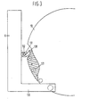
- Fig. 3 depicts the carrier support 6 having a support arm 130 for supporting cylinder 7.
- a spring-loaded, movable trigger 131 At or near the base of carrier support 6, is a spring-loaded, movable trigger 131.
- the movable trigger 131 of carrier support 6 interacts with the catch pins 120 extending from table 10 to cause sufficient rotation of sample table 10 to provide a new encapsulated sample during each cycle of operation.
- the trigger 131 of carrier support 6 catches one catch pin 120 in a manner such that table 10 rotates half the distance required to place a new sample under vacuum nozzle 9.
- the carrier support 6 is returned to its original position, there is no movement in the sample table 10 when trigger 131 contacts a catch pin 120 owing to the partial rotation of trigger 131 around the catch pin.
- trigger 131 is returned to its original position by spring 132.
- piston 5 is extended to remove the tested sample from the DSC cell, the contact of trigger 131 with catch pin 120 rotates the sample table 10 sufficiently to place the new sample directly under nozzle 9.
- Fig. 4 illustrates a preferred cover means, insulating sleeve, and protective hood.
- the preferred cover means 20 comprises a gas- permeable disk or plate 106, whose permeability permits the passage of gases through plate or disk 106, and a continuous plate or disk 107 which is essentially impermeable to the passage of gas therethrough.
- Permeable plate 106 and non-permeable plate 107 are connected or joined by means of a permeable conduit 104 which allows the passage of gas from the interior of the conduit to the environment.
- gases flowing through the passage(s) or perforation(s) in plate 106 can flow through the passage(s) or perforation(s) in the conduit 104.
- any gases generated are free to escape from the receptacle containing the sample, thereby preventing an excessive pressure buildup therein.
- a controlled atmosphere can be maintained within the receptacle by purging the cell using a suitable purge gas.
- top plate 107 is essentially impermeable to the passage of gas, a vacuum can be effectively applied to the top surface thereof and not readily be dissipated. As a result, the cover means is easily moved by the vacuum cup 16 during the removal and replacement operation.
- Insulating sleeve 18 is shown with a container 19 affixed thereto.
- Container 19 has space provided for receiving the cover means 20 after its removal from the measuring cell 92.
- the protective hood 17 has a receptacle 101 for receiving insulating sleeve 18.
- the receptacle 101 is advantageously tapered and conforms to the shape of the insulating sleeve 18.
- a receiving ring 100 such as depicted in the embodiment illustrated in Fig. 4, for receiving hood 17 upon its removal from around the DSC cell is also advantageously employed herein.
- Receiving ring 100 comprises a receptacle 108 which is preferably tapered and conforms to the shape of the protective hood 17.
- the described receptacles 119, 101 and 100 ensure proper placement of the cover means, insulating sleeve and protective hood upon their sequential removal from the DSC cell, thereby ensuring continuous and repeatable performance of the sample handling device.
- the cylinders 3, 7, 12 and 14 are advantageously air-activated, and, where necessary to dampen vibration, supplemented by the presence of oil.
- each cylinder is capable of being activated by a single source of air.
- the vacuum nozzle 9 and vacuum cup 16 are designed so that, with the same vacuum, vacuum nozzle 9 is capable of transporting the encapsulated sample without significant damage occurring thereto and vacuum cup 16 is capable of securely transporting the cover means, insulating sleeve and protective hood.
- the nozzle 9 and vacuum cup 16 illustrated in the Figs. are merely representative of a design that can be suitably employed herein. Vacuum nozzles and/or cups of other design capable of performing the same function are also suitably employed herein.
Landscapes
- Engineering & Computer Science (AREA)
- Robotics (AREA)
- Physics & Mathematics (AREA)
- Health & Medical Sciences (AREA)
- Life Sciences & Earth Sciences (AREA)
- Chemical & Material Sciences (AREA)
- Analytical Chemistry (AREA)
- Biochemistry (AREA)
- General Health & Medical Sciences (AREA)
- General Physics & Mathematics (AREA)
- Immunology (AREA)
- Pathology (AREA)
- Sampling And Sample Adjustment (AREA)
- Investigating Or Analyzing Materials Using Thermal Means (AREA)
- Centrifugal Separators (AREA)
- Automatic Analysis And Handling Materials Therefor (AREA)
- Electron Tubes For Measurement (AREA)
Claims (5)
Priority Applications (1)
| Application Number | Priority Date | Filing Date | Title |
|---|---|---|---|
| AT84200209T ATE39290T1 (de) | 1983-02-16 | 1984-02-16 | Vorrichtung zur automatischen probenuebertragung. |
Applications Claiming Priority (2)
| Application Number | Priority Date | Filing Date | Title |
|---|---|---|---|
| NL8300586 | 1983-02-16 | ||
| NL8300586A NL8300586A (nl) | 1983-02-16 | 1983-02-16 | Inrichting en werkwijze voor het automatisch hanteren van monsters. |
Publications (2)
| Publication Number | Publication Date |
|---|---|
| EP0117006A1 EP0117006A1 (de) | 1984-08-29 |
| EP0117006B1 true EP0117006B1 (de) | 1988-12-14 |
Family
ID=19841427
Family Applications (1)
| Application Number | Title | Priority Date | Filing Date |
|---|---|---|---|
| EP84200209A Expired EP0117006B1 (de) | 1983-02-16 | 1984-02-16 | Vorrichtung zur automatischen Probenübertragung |
Country Status (5)
| Country | Link |
|---|---|
| EP (1) | EP0117006B1 (de) |
| AT (1) | ATE39290T1 (de) |
| CA (1) | CA1206772A (de) |
| DE (1) | DE3475652D1 (de) |
| NL (1) | NL8300586A (de) |
Families Citing this family (2)
| Publication number | Priority date | Publication date | Assignee | Title |
|---|---|---|---|---|
| US4816730A (en) * | 1986-12-22 | 1989-03-28 | E. I. Du Pont De Nemours And Company | Autosampler |
| JP3016095B2 (ja) * | 1990-11-29 | 2000-03-06 | セイコーインスツルメンツ株式会社 | 熱重量測定装置 |
Family Cites Families (3)
| Publication number | Priority date | Publication date | Assignee | Title |
|---|---|---|---|---|
| DE2353793B1 (de) * | 1973-10-26 | 1975-03-20 | Siemens Ag | Rotierende Vorrichtung zum selbsttaetigen Eingeben flacher Proben in ein Analysegeraet |
| US4005782A (en) * | 1974-03-04 | 1977-02-01 | Engineered Metal Products Company, Inc. | Picker |
| FR2418702A1 (fr) * | 1978-03-01 | 1979-09-28 | Commissariat Energie Atomique | Dispositif automatique de pesee et de vidange d'un produit contenu dans un recipient muni d'un couvercle |
-
1983
- 1983-02-16 NL NL8300586A patent/NL8300586A/nl not_active Application Discontinuation
-
1984
- 1984-02-15 CA CA000447547A patent/CA1206772A/en not_active Expired
- 1984-02-16 DE DE8484200209T patent/DE3475652D1/de not_active Expired
- 1984-02-16 EP EP84200209A patent/EP0117006B1/de not_active Expired
- 1984-02-16 AT AT84200209T patent/ATE39290T1/de active
Also Published As
| Publication number | Publication date |
|---|---|
| CA1206772A (en) | 1986-07-02 |
| NL8300586A (nl) | 1984-09-17 |
| EP0117006A1 (de) | 1984-08-29 |
| DE3475652D1 (en) | 1989-01-19 |
| ATE39290T1 (de) | 1988-12-15 |
Similar Documents
| Publication | Publication Date | Title |
|---|---|---|
| US4801429A (en) | Automatic sample handling device | |
| US6705827B2 (en) | Robotic seed-handling apparatus and methods | |
| CN114901423B (zh) | 相位执行器装配线 | |
| EP1455175B1 (de) | Analysator von Feuchtigkeit oder Asche in gemischten Proben | |
| CA2152353A1 (en) | Method for automatic testing of laboratory specimens | |
| JP2006504070A (ja) | 坩堝と試料を自動的に装填するシステム及び方法 | |
| US5398556A (en) | Device for charging a measuring apparatus for thermal analysis with material specimens filled into containers | |
| EP0117006B1 (de) | Vorrichtung zur automatischen Probenübertragung | |
| CN109490560A (zh) | 一种煤样自动检测系统及方法 | |
| CN117586865A (zh) | 具有自动采样的操纵装置的屏障系统和自动采样的方法 | |
| CN111351735A (zh) | 核燃料芯块水浸密度自动测量装置 | |
| US4539645A (en) | Automated sample analyzer for induction furnace analysis | |
| US7449152B2 (en) | Methods and apparatus for handling compound storage vessels | |
| CN119973620B (zh) | 汽车水箱压力帽装配系统 | |
| CN112305193B (zh) | 一种煤质工业分析仪 | |
| JPH0519106B2 (de) | ||
| CN216869453U (zh) | 一种盖板尺寸外观检测仪 | |
| KR20250085783A (ko) | 소모성 여과 유닛들을 사용하여 액체들을 테스트하기 위한 여과 시스템 및 자동화된 여과 프로세스 | |
| AU2008200146A1 (en) | Automatic sample handling apparatus | |
| US20250059489A1 (en) | Arrangement for classifying plant embryos | |
| JPH07198460A (ja) | 結合装置 | |
| CN209342228U (zh) | 一种用于恒温恒湿自动称重系统中的标准砝码取放装置 | |
| CN219391710U (zh) | 具有机械臂的水分测试仪及水分检测设备 | |
| WO2025202232A1 (en) | Automated environmental sampling device | |
| CN213729915U (zh) | 一种超声波焊接设备 |
Legal Events
| Date | Code | Title | Description |
|---|---|---|---|
| PUAI | Public reference made under article 153(3) epc to a published international application that has entered the european phase |
Free format text: ORIGINAL CODE: 0009012 |
|
| AK | Designated contracting states |
Designated state(s): AT BE CH DE FR GB IT LI NL SE |
|
| 17P | Request for examination filed |
Effective date: 19840816 |
|
| 17Q | First examination report despatched |
Effective date: 19860206 |
|
| GRAA | (expected) grant |
Free format text: ORIGINAL CODE: 0009210 |
|
| AK | Designated contracting states |
Kind code of ref document: B1 Designated state(s): AT BE CH DE FR GB IT LI NL SE |
|
| PG25 | Lapsed in a contracting state [announced via postgrant information from national office to epo] |
Ref country code: IT Free format text: LAPSE BECAUSE OF FAILURE TO SUBMIT A TRANSLATION OF THE DESCRIPTION OR TO PAY THE FEE WITHIN THE PRESCRIBED TIME-LIMIT;WARNING: LAPSES OF ITALIAN PATENTS WITH EFFECTIVE DATE BEFORE 2007 MAY HAVE OCCURRED AT ANY TIME BEFORE 2007. THE CORRECT EFFECTIVE DATE MAY BE DIFFERENT FROM THE ONE RECORDED. Effective date: 19881214 Ref country code: BE Effective date: 19881214 |
|
| REF | Corresponds to: |
Ref document number: 39290 Country of ref document: AT Date of ref document: 19881215 Kind code of ref document: T |
|
| REF | Corresponds to: |
Ref document number: 3475652 Country of ref document: DE Date of ref document: 19890119 |
|
| ET | Fr: translation filed | ||
| PLBE | No opposition filed within time limit |
Free format text: ORIGINAL CODE: 0009261 |
|
| STAA | Information on the status of an ep patent application or granted ep patent |
Free format text: STATUS: NO OPPOSITION FILED WITHIN TIME LIMIT |
|
| 26N | No opposition filed | ||
| EAL | Se: european patent in force in sweden |
Ref document number: 84200209.9 |
|
| PGFP | Annual fee paid to national office [announced via postgrant information from national office to epo] |
Ref country code: FR Payment date: 19951213 Year of fee payment: 13 |
|
| PGFP | Annual fee paid to national office [announced via postgrant information from national office to epo] |
Ref country code: SE Payment date: 19951215 Year of fee payment: 13 |
|
| PGFP | Annual fee paid to national office [announced via postgrant information from national office to epo] |
Ref country code: DE Payment date: 19951219 Year of fee payment: 13 |
|
| PGFP | Annual fee paid to national office [announced via postgrant information from national office to epo] |
Ref country code: GB Payment date: 19960102 Year of fee payment: 13 |
|
| PGFP | Annual fee paid to national office [announced via postgrant information from national office to epo] |
Ref country code: CH Payment date: 19960207 Year of fee payment: 13 |
|
| PGFP | Annual fee paid to national office [announced via postgrant information from national office to epo] |
Ref country code: NL Payment date: 19960229 Year of fee payment: 13 |
|
| PGFP | Annual fee paid to national office [announced via postgrant information from national office to epo] |
Ref country code: AT Payment date: 19961212 Year of fee payment: 14 |
|
| PG25 | Lapsed in a contracting state [announced via postgrant information from national office to epo] |
Ref country code: GB Effective date: 19970216 |
|
| PG25 | Lapsed in a contracting state [announced via postgrant information from national office to epo] |
Ref country code: SE Effective date: 19970217 |
|
| PG25 | Lapsed in a contracting state [announced via postgrant information from national office to epo] |
Ref country code: LI Effective date: 19970228 Ref country code: CH Effective date: 19970228 |
|
| PG25 | Lapsed in a contracting state [announced via postgrant information from national office to epo] |
Ref country code: NL Effective date: 19970901 |
|
| GBPC | Gb: european patent ceased through non-payment of renewal fee |
Effective date: 19970216 |
|
| REG | Reference to a national code |
Ref country code: CH Ref legal event code: PL |
|
| PG25 | Lapsed in a contracting state [announced via postgrant information from national office to epo] |
Ref country code: FR Effective date: 19971030 |
|
| PG25 | Lapsed in a contracting state [announced via postgrant information from national office to epo] |
Ref country code: DE Effective date: 19971101 |
|
| EUG | Se: european patent has lapsed |
Ref document number: 84200209.9 |
|
| NLV4 | Nl: lapsed or anulled due to non-payment of the annual fee |
Effective date: 19970901 |
|
| REG | Reference to a national code |
Ref country code: FR Ref legal event code: ST |
|
| PG25 | Lapsed in a contracting state [announced via postgrant information from national office to epo] |
Ref country code: AT Free format text: LAPSE BECAUSE OF NON-PAYMENT OF DUE FEES Effective date: 19980216 |