EP0117076A2 - Kontaktmittel für Flüssigkeit und Gas - Google Patents
Kontaktmittel für Flüssigkeit und Gas Download PDFInfo
- Publication number
- EP0117076A2 EP0117076A2 EP84300509A EP84300509A EP0117076A2 EP 0117076 A2 EP0117076 A2 EP 0117076A2 EP 84300509 A EP84300509 A EP 84300509A EP 84300509 A EP84300509 A EP 84300509A EP 0117076 A2 EP0117076 A2 EP 0117076A2
- Authority
- EP
- European Patent Office
- Prior art keywords
- duct
- ridges
- depression
- plate
- means according
- Prior art date
- Legal status (The legal status is an assumption and is not a legal conclusion. Google has not performed a legal analysis and makes no representation as to the accuracy of the status listed.)
- Withdrawn
Links
- 239000007788 liquid Substances 0.000 title claims abstract description 8
- 238000012856 packing Methods 0.000 claims abstract description 18
- 238000001816 cooling Methods 0.000 claims abstract description 15
- 230000001154 acute effect Effects 0.000 claims description 11
- XLYOFNOQVPJJNP-UHFFFAOYSA-N water Substances O XLYOFNOQVPJJNP-UHFFFAOYSA-N 0.000 description 7
- 239000000463 material Substances 0.000 description 5
- 239000007789 gas Substances 0.000 description 3
- 239000011324 bead Substances 0.000 description 2
- 229920003023 plastic Polymers 0.000 description 2
- 239000004033 plastic Substances 0.000 description 2
- 230000015572 biosynthetic process Effects 0.000 description 1
- 239000000112 cooling gas Substances 0.000 description 1
- 230000000694 effects Effects 0.000 description 1
- 238000001704 evaporation Methods 0.000 description 1
- 230000008020 evaporation Effects 0.000 description 1
- 239000003292 glue Substances 0.000 description 1
- 230000005484 gravity Effects 0.000 description 1
- 229910001220 stainless steel Inorganic materials 0.000 description 1
- 239000010935 stainless steel Substances 0.000 description 1
Images




Classifications
-
- F—MECHANICAL ENGINEERING; LIGHTING; HEATING; WEAPONS; BLASTING
- F28—HEAT EXCHANGE IN GENERAL
- F28F—DETAILS OF HEAT-EXCHANGE AND HEAT-TRANSFER APPARATUS, OF GENERAL APPLICATION
- F28F25/00—Component parts of trickle coolers
- F28F25/02—Component parts of trickle coolers for distributing, circulating, and accumulating liquid
- F28F25/08—Splashing boards or grids, e.g. for converting liquid sprays into liquid films; Elements or beds for increasing the area of the contact surface
- F28F25/087—Vertical or inclined sheets; Supports or spacers
-
- B—PERFORMING OPERATIONS; TRANSPORTING
- B01—PHYSICAL OR CHEMICAL PROCESSES OR APPARATUS IN GENERAL
- B01D—SEPARATION
- B01D45/00—Separating dispersed particles from gases or vapours by gravity, inertia, or centrifugal forces
- B01D45/04—Separating dispersed particles from gases or vapours by gravity, inertia, or centrifugal forces by utilising inertia
- B01D45/06—Separating dispersed particles from gases or vapours by gravity, inertia, or centrifugal forces by utilising inertia by reversal of direction of flow
-
- B—PERFORMING OPERATIONS; TRANSPORTING
- B01—PHYSICAL OR CHEMICAL PROCESSES OR APPARATUS IN GENERAL
- B01D—SEPARATION
- B01D45/00—Separating dispersed particles from gases or vapours by gravity, inertia, or centrifugal forces
- B01D45/04—Separating dispersed particles from gases or vapours by gravity, inertia, or centrifugal forces by utilising inertia
- B01D45/08—Separating dispersed particles from gases or vapours by gravity, inertia, or centrifugal forces by utilising inertia by impingement against baffle separators
-
- B—PERFORMING OPERATIONS; TRANSPORTING
- B01—PHYSICAL OR CHEMICAL PROCESSES OR APPARATUS IN GENERAL
- B01J—CHEMICAL OR PHYSICAL PROCESSES, e.g. CATALYSIS OR COLLOID CHEMISTRY; THEIR RELEVANT APPARATUS
- B01J19/00—Chemical, physical or physico-chemical processes in general; Their relevant apparatus
- B01J19/32—Packing elements in the form of grids or built-up elements for forming a unit or module inside the apparatus for mass or heat transfer
-
- B—PERFORMING OPERATIONS; TRANSPORTING
- B01—PHYSICAL OR CHEMICAL PROCESSES OR APPARATUS IN GENERAL
- B01J—CHEMICAL OR PHYSICAL PROCESSES, e.g. CATALYSIS OR COLLOID CHEMISTRY; THEIR RELEVANT APPARATUS
- B01J2219/00—Chemical, physical or physico-chemical processes in general; Their relevant apparatus
- B01J2219/32—Details relating to packing elements in the form of grids or built-up elements for forming a unit of module inside the apparatus for mass or heat transfer
- B01J2219/322—Basic shape of the elements
- B01J2219/32203—Sheets
- B01J2219/3221—Corrugated sheets
-
- B—PERFORMING OPERATIONS; TRANSPORTING
- B01—PHYSICAL OR CHEMICAL PROCESSES OR APPARATUS IN GENERAL
- B01J—CHEMICAL OR PHYSICAL PROCESSES, e.g. CATALYSIS OR COLLOID CHEMISTRY; THEIR RELEVANT APPARATUS
- B01J2219/00—Chemical, physical or physico-chemical processes in general; Their relevant apparatus
- B01J2219/32—Details relating to packing elements in the form of grids or built-up elements for forming a unit of module inside the apparatus for mass or heat transfer
- B01J2219/322—Basic shape of the elements
- B01J2219/32203—Sheets
- B01J2219/32213—Plurality of essentially parallel sheets
-
- B—PERFORMING OPERATIONS; TRANSPORTING
- B01—PHYSICAL OR CHEMICAL PROCESSES OR APPARATUS IN GENERAL
- B01J—CHEMICAL OR PHYSICAL PROCESSES, e.g. CATALYSIS OR COLLOID CHEMISTRY; THEIR RELEVANT APPARATUS
- B01J2219/00—Chemical, physical or physico-chemical processes in general; Their relevant apparatus
- B01J2219/32—Details relating to packing elements in the form of grids or built-up elements for forming a unit of module inside the apparatus for mass or heat transfer
- B01J2219/322—Basic shape of the elements
- B01J2219/32203—Sheets
- B01J2219/32248—Sheets comprising areas that are raised or sunken from the plane of the sheet
- B01J2219/32251—Dimples, bossages, protrusions
-
- B—PERFORMING OPERATIONS; TRANSPORTING
- B01—PHYSICAL OR CHEMICAL PROCESSES OR APPARATUS IN GENERAL
- B01J—CHEMICAL OR PHYSICAL PROCESSES, e.g. CATALYSIS OR COLLOID CHEMISTRY; THEIR RELEVANT APPARATUS
- B01J2219/00—Chemical, physical or physico-chemical processes in general; Their relevant apparatus
- B01J2219/32—Details relating to packing elements in the form of grids or built-up elements for forming a unit of module inside the apparatus for mass or heat transfer
- B01J2219/324—Composition or microstructure of the elements
- B01J2219/32408—Metal
-
- B—PERFORMING OPERATIONS; TRANSPORTING
- B01—PHYSICAL OR CHEMICAL PROCESSES OR APPARATUS IN GENERAL
- B01J—CHEMICAL OR PHYSICAL PROCESSES, e.g. CATALYSIS OR COLLOID CHEMISTRY; THEIR RELEVANT APPARATUS
- B01J2219/00—Chemical, physical or physico-chemical processes in general; Their relevant apparatus
- B01J2219/32—Details relating to packing elements in the form of grids or built-up elements for forming a unit of module inside the apparatus for mass or heat transfer
- B01J2219/324—Composition or microstructure of the elements
- B01J2219/32483—Plastics
-
- Y—GENERAL TAGGING OF NEW TECHNOLOGICAL DEVELOPMENTS; GENERAL TAGGING OF CROSS-SECTIONAL TECHNOLOGIES SPANNING OVER SEVERAL SECTIONS OF THE IPC; TECHNICAL SUBJECTS COVERED BY FORMER USPC CROSS-REFERENCE ART COLLECTIONS [XRACs] AND DIGESTS
- Y10—TECHNICAL SUBJECTS COVERED BY FORMER USPC
- Y10S—TECHNICAL SUBJECTS COVERED BY FORMER USPC CROSS-REFERENCE ART COLLECTIONS [XRACs] AND DIGESTS
- Y10S261/00—Gas and liquid contact apparatus
- Y10S261/11—Cooling towers
-
- Y—GENERAL TAGGING OF NEW TECHNOLOGICAL DEVELOPMENTS; GENERAL TAGGING OF CROSS-SECTIONAL TECHNOLOGIES SPANNING OVER SEVERAL SECTIONS OF THE IPC; TECHNICAL SUBJECTS COVERED BY FORMER USPC CROSS-REFERENCE ART COLLECTIONS [XRACs] AND DIGESTS
- Y10—TECHNICAL SUBJECTS COVERED BY FORMER USPC
- Y10T—TECHNICAL SUBJECTS COVERED BY FORMER US CLASSIFICATION
- Y10T428/00—Stock material or miscellaneous articles
- Y10T428/24—Structurally defined web or sheet [e.g., overall dimension, etc.]
- Y10T428/24628—Nonplanar uniform thickness material
- Y10T428/24669—Aligned or parallel nonplanarities
- Y10T428/24694—Parallel corrugations
- Y10T428/24711—Plural corrugated components
Definitions
- the invention relates to liquid/gas contact means and more particularly but not exclusively to an evaporative water cooling tower packing.
- Another object of the invention is to provide a packing which can be used both in crossflow and counterflow cooling towers.
- a plate for assembly with similar plates to form a cooling tower packing comprising a series of parallel mutually spaced ridges which are generally triangular in transverse cross-section.
- the ridges form means for spacing apart adjacent sheets and define the opposite sides of at least one duct when the plates are assembled together.
- the plates are preferably formed, e.g. thermoformed, from sheet material so that the reverse sides of the ridges form depressions which are V-shaped in transverse cross-section.
- the ridges may extend over a major part of the plate and preferably they extend over substantially the whole of the plate.
- the included angle between the sides of the V-shaped depression may be an acute angle, preferably not greater than 45°.
- the acute angle is between 36 and 40°, and the preferred acute angle is 38°.
- the transverse cross-sectional area of the depression may be between 5 and 20% of the transverse cross-sectional area defined between adjacent ridges, and advantageously is between 10 and 14%.
- the preferred cross-sectional area is between 12 and 13%.
- the plates are formed with a series of projections disposed between the ridges, the projections being small in height in comparison with the ridges.
- the projections may be generally semi-circular in transverse cross-section.
- I provide a projection disposed centrally of a pair of ridges and extending parallel therewith and a plurality of laterally extending projections disposed on opposite sides of the centrally disposed projection.
- the arrangement is such that the length and configuration of the longitudinal projections correspond to the length and configuration of the crests of the ridges whereby the plates may be assembled one against another with the crests of the ridges received in small recesses or depressions on one side of the plates formed by the longitudinal projections so that the plates are firmly located one against another.
- the plate comprises at least one first part, at least one intermediate part and at least one third part, the first and thrid parts being disposed in parallel planes, and the second part, which is disposed between the first and third parts being disposed in a plane which is oblique with respect to the said parallel planes.
- each ridge extends into all three parts of the plate.
- the ridges may be discontinuous along their lengths, and preferably the discontinuities in adjacent ridges are staggered one from the other.
- the invention provides means for effecting liquid/gas contact comprising a duct formed with a depression which extends along the duct.
- the depression extends over a major part of the length of the duct, and advantageously the depression extends over substantially the whole length of the duct.
- the depression may be generally V-shaped in transverse cross-section and the included angle between the sides of the V-shaped depression may be an acute angle.
- the acute angle is not greater than 45° and may be in the range 36 to 40°. The preferred angle is 38°.
- the volume of the depression may be between 5 and 20% of the volume of the duct, and the preferred volume of the depression is between 12 and 13% of the volume of the duct.
- the duct excluding the depression may be trapezoidal in transverse cross-sectional shape and preferably the depression is located on the longer of the pair of parallel sides of the duct.
- the depression is centrally located on the longer of the pair of parallel sides.
- At least one projection extends into the duct from the side thereof opposite to the depression.
- the or each projection may be generally semi-circular in transverse cross-sectional shape.
- the entry to the duct may be of smaller transverse cross-sectional area than the interior of the duct, and preferably the duct changes direction at least once along its length.
- the duct may comprise an entry section and an exit section which are mutually parallel and may be co-planar and at least one obliquely extending section between the parallel sections.
- the invention is a packing for a cooling tower comprising an assembly of plates as described above.
- an evaporative water cooling tower packing which consists of a series of plates 1 thermoformed from sheet plastics material, although other materials such as stainless steel sheet might also be suitable.
- Each plate comprises generally flat portions 10, 11 and 12 respectively, the arrangement being such that the portions 11 and 12 are disposed in mutually parallel planes and are separated by the portions 10, the planes of which extend obliquely to the planes of the portions 11 and 12.
- the portions 10 are somewhat larger in size than the portions 11 and 12.
- the plate has marginal portions 14 on opposite sides, which portions 14 are co-planar with the portion 12 and from which extend side walls 5 which connect to the opposite edges of the portions 10 and 11 to lend rigidity to the plate.
- Abutments 6 project from the side walls 5 to assist stacking of a series of the plates one upon the other to form the packing. Stacking of the sheets is more fully described below.
- Each plate is formed with a series of parallel mutually spaced ridges 2 which may extend continuously from one end of the plate to the other. As shown in Figure 1 however each ridge starts in a portion 11, extends through a portion 10 and is interupted by a short gap in each portion 11. Each ridge is triangular in transverse cross-section.
- the surfaces of the portions 10, 11 and 12 between the ridges 2 are each formed with a projection or bead 3 disposed centrally between an adjacent pair of ridges and extending parallel thereto and over substantially the whole length thereof.
- a transverse bead of projection 7 is disposed at the end of the projection 3 in the portion 12 and a similar transverse projection 8 is disposed at the end of the projection 3 in the portion 11.
- both of the projections 7 and 8 are disposed adjacent to, but out of contact with, the ends of the projection 3 and also the ends of the projections 7 and 8 are disposed adjacent to, but out of contact with, the ridges 2.
- the ends of the projections 4 are out of contact with the projection 3 and the ridges 2. It might however be desirable to continue the projections 3, 4, 7 and 8 to meet one another and the ridges 2 to inhibit the formation of rivulets of water.
- each plate is made from sheet material the undersurface of each plate is formed (as shown in Figure 3) with recesses or depressions corresponding to the longitudinal projections 3, the transverse projections 4, 7 and 8 and the ridges 2.
- the depressions corresponding to the ridges 2 are indicated at 2', and similarly the recesses or depressions corresponding to the longitudinal projections 3 are shown at 3', and the depressions corresponding to the transverse projections 4, 7 and 8 at 4', 7' and 8' respectively.
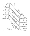
- the plates described above are stacked together to form a packing as shown in Figures 1 and 4 to 6 and comprising a plurality of sinuous ducts 9 through which water is passed under the action of gravity so that the water flows as a film over the surfaces of the ducts while air is forced in countercurrent through the ducts to cool the water, e.g. by evaporation.
- the sides 5 of the plates are formed with projections 6 and these projections are arranged to abut against the undersides of the marginal portions 14 of the adjacent plates to achieve the correct spacing between the plates.
- the crests of the ridges 2 locate in the depressions 3' formed by the undersurfaces of the projections 3.
- each duct 9 is generally trapezoidal in transverse cross-section and is defined on opposite sides by an adjacent pair of ridges 2.
- One of the pair of parallel sides of each duct 9 is formed with the projections 3, 4, 7 and 8 while the opposite sides is formed with small depressions 4' and with a large centrally disposed longitudinal depression 2'.
- the angle between the walls of the depression 2' is 38°, and the volume of the depression 2' represents around 13% of the volume of the duct as a whole.
- the mean hydraulic radius of the duct i.e. the cross-sectional area of the duct divided by the length of the perimeter of the duct, is around 8.75.
- each duct 9 comprises an entrance section 15 defined by the lowermost portions 12 of adjacent pairs of plates, four obliquely extending sections 16 defined by the portions 10 of adjacent pairs of plates, three intermediate sections 18 defined between portions 11 of adjacent plates and an exit section 17 defined by the uppermost portions 12 of adjacent pairs of plates.
- the ridges 2 and projections 3, 4, 7 and 8 terminate short of the entrances to the ducts 9 so that the cross-sectional area of each duct entrance is smaller than the cross-sectional area of the interior of the duct. This is also true of the duct exits. Since the ridges 2 are discontinuous in the intermediate sections 18, the ducts communicate with one another which will help to distribute evenly the water to be cooled to prevent overload of some ducts.
- each ridge 2 is discontinuous in the portions 10 of the plate and is divided into a series of generally pyramidal members 2" to permit air to be blown cross-wise through an assembly of plates.
- the members 2" in each ridge are staggered to force the cooling air to follow a sinuous path through the packing. It will be appreciated that the members 2" may have shapes other than pyramidal and still achieve the same effect.
- the ridges 2 although equi-spaced one from another are asymmetric on the surface of the plate.
- one plate is turned through 180 0 with respect to the adjacent plates so that the ridges 2 on one plate are staggered from the ridges 2 of the adjacent plates.
- the edges of the plates may be secured one to the other by glue and/or may be mounted in a surrounding framework. Before the plates are turned as described above to assemble the stack, they rest one within the other and so take up the minimum space for storage and transport.
Landscapes
- Chemical & Material Sciences (AREA)
- Chemical Kinetics & Catalysis (AREA)
- Engineering & Computer Science (AREA)
- Thermal Sciences (AREA)
- Physics & Mathematics (AREA)
- Mechanical Engineering (AREA)
- Organic Chemistry (AREA)
- General Engineering & Computer Science (AREA)
- Physical Or Chemical Processes And Apparatus (AREA)
- Vaporization, Distillation, Condensation, Sublimation, And Cold Traps (AREA)
- Glass Compositions (AREA)
- Control Of Motors That Do Not Use Commutators (AREA)
- Inorganic Insulating Materials (AREA)
- Separating Particles In Gases By Inertia (AREA)
- Gas Separation By Absorption (AREA)
Applications Claiming Priority (2)
| Application Number | Priority Date | Filing Date | Title |
|---|---|---|---|
| GB838304683A GB8304683D0 (en) | 1983-02-19 | 1983-02-19 | Moisture eliminator |
| GB8304683 | 1983-02-19 |
Publications (2)
| Publication Number | Publication Date |
|---|---|
| EP0117076A2 true EP0117076A2 (de) | 1984-08-29 |
| EP0117076A3 EP0117076A3 (de) | 1984-10-17 |
Family
ID=10538306
Family Applications (2)
| Application Number | Title | Priority Date | Filing Date |
|---|---|---|---|
| EP84300509A Withdrawn EP0117076A3 (de) | 1983-02-19 | 1984-01-27 | Kontaktmittel für Flüssigkeit und Gas |
| EP84300510A Expired EP0117077B1 (de) | 1983-02-19 | 1984-01-27 | Entfeuchter |
Family Applications After (1)
| Application Number | Title | Priority Date | Filing Date |
|---|---|---|---|
| EP84300510A Expired EP0117077B1 (de) | 1983-02-19 | 1984-01-27 | Entfeuchter |
Country Status (6)
| Country | Link |
|---|---|
| US (2) | US4579693A (de) |
| EP (2) | EP0117076A3 (de) |
| AT (1) | ATE40001T1 (de) |
| DE (1) | DE3476115D1 (de) |
| GB (1) | GB8304683D0 (de) |
| IN (2) | IN160253B (de) |
Cited By (4)
| Publication number | Priority date | Publication date | Assignee | Title |
|---|---|---|---|---|
| EP0229199A1 (de) * | 1985-12-17 | 1987-07-22 | H-PANNONPLAST Müanyagipari Vallalat | Packung mit Filmströmung für die biologische Aufbereitung von Flüssigkeiten |
| EP1004839A3 (de) * | 1998-11-25 | 2001-01-24 | Baltimore Aircoil Company, Inc. | Füllkörper mit Filmströmung, mit Gaswirbelströmung für Kontaktvorrichtung mit Stoff- und Wärmeaustausch, mit Rieselplatten mit Distanzstücken |
| CN107478088A (zh) * | 2016-06-07 | 2017-12-15 | 日本斯频德制造株式会社 | 用于冷却塔的填充板及其制作方法 |
| CN111609751A (zh) * | 2016-06-03 | 2020-09-01 | 日本斯频德制造株式会社 | 气液接触用填充板 |
Families Citing this family (19)
| Publication number | Priority date | Publication date | Assignee | Title |
|---|---|---|---|---|
| CH655787A5 (fr) * | 1983-12-30 | 1986-05-15 | Engetra Sa | Dispositif de garnissage d'une installation de mise en contact de liquide et de gaz et son procede de fabrication. |
| HU195314B (en) * | 1985-07-23 | 1988-04-28 | Villamos Ipari Kutato Intezet | Cooling insert for equipments carrying out heat and material exchange being between gaseous medium and fluid particularly for cooling towers and degasing units |
| ATE44413T1 (de) * | 1985-11-08 | 1989-07-15 | Energiagazdalkodasi Intezet | Vorrichtung zur steigerung des waerme- und/oder stoffaustausches zwischen einem gas und einer fluessigkeit. |
| US4968328A (en) * | 1986-05-16 | 1990-11-06 | Duke Eddie D | De-mister baffle and assembly |
| SE461018B (sv) * | 1987-07-06 | 1989-12-18 | Svenska Emmisionsteknik Ab | Katalysatorbaerare |
| AU638875B2 (en) * | 1990-11-27 | 1993-07-08 | Koch (Cyprus) Limited | Tower packing with louvers |
| US5203894A (en) * | 1992-04-03 | 1993-04-20 | Munters Corporation | Mist eliminator blade spacer |
| US5518604A (en) * | 1995-04-07 | 1996-05-21 | Brandeis University | Buffer shaping device |
| US5624733A (en) * | 1995-06-27 | 1997-04-29 | The Boc Group, Inc. | Structured packing |
| DE19733480C2 (de) * | 1997-08-01 | 1999-06-24 | Gea Kuehlturmbau Gmbh | Einbaupackung zum Stoff- und/oder Wärmeaustausch zwischen Gasen und Flüssigkeiten |
| US6315804B1 (en) * | 2000-01-07 | 2001-11-13 | Evapco International, Inc. | Drift eliminator |
| GB0308745D0 (en) * | 2003-04-16 | 2003-05-21 | Wigley Albert F | Drift eliminator |
| CA2456375A1 (en) * | 2004-01-27 | 2005-07-27 | Alberta Research Council, Inc. | Method and apparatus for separating particles from a gas stream |
| DE102004025336B4 (de) * | 2004-05-19 | 2006-06-29 | Hewitech Gmbh & Co. Kg | Einbauelement für einen von einem Fluid durchströmbaren Hohlraum |
| DE102005056543B4 (de) * | 2005-11-28 | 2016-01-14 | Rea Plastik Tech Gmbh | Tropfenabscheider für einen Gaswäscher |
| US7674304B2 (en) * | 2008-06-26 | 2010-03-09 | Brentwood Industries, Inc. | Drift eliminator with formed beveled tip |
| US20160223262A1 (en) * | 2014-10-31 | 2016-08-04 | Baltimore Aircoil Company, Inc. | Cooling tower integrated inlet louver fill |
| US10393441B2 (en) * | 2015-06-02 | 2019-08-27 | Spx Cooling Technologies, Inc. | Cooling tower drift eliminator |
| US11988451B2 (en) * | 2020-04-23 | 2024-05-21 | Brentwood Industries, Inc. | Drift eliminator and method of making |
Family Cites Families (39)
| Publication number | Priority date | Publication date | Assignee | Title |
|---|---|---|---|---|
| DE70920C (de) * | J. MAEMECKE in Berlin, Friedenstr. 31 | Ventilsteuerung für Pumpen mit Oeffnen der Druck- und Saugventile vor dem Hubwechsel | ||
| AU483705B (en) * | 1905-12-18 | 1907-01-15 | Reginald Angus Arthur | Improvements in the running gear of railway cars (I |
| US947393A (en) * | 1908-05-28 | 1910-01-25 | Josef Muchka | Separator. |
| DE384218C (de) * | 1920-09-23 | 1923-10-30 | Luftfilter Baugesellschaft M B | Abscheideplatte |
| FR28545E (fr) * | 1923-12-28 | 1925-03-10 | Monture pour double-rideau | |
| US1834981A (en) * | 1928-04-02 | 1931-12-08 | Albert H Stebbins | Air classifier |
| US1926924A (en) * | 1928-04-30 | 1933-09-12 | American Air Filter Co | Sinuous air filter and medium |
| DE863816C (de) * | 1951-07-03 | 1953-01-19 | Ahlborn E Ag | Plattenwaermeaustauscher mit parallelen gewellten Waenden |
| US2793017A (en) * | 1954-10-04 | 1957-05-21 | Dow Chemical Co | Apparatus for distributing falling liquid in thin films |
| US2959257A (en) * | 1957-03-18 | 1960-11-08 | James R Campbell | Honeycomb core and panel utilizing same |
| US3151675A (en) * | 1957-04-02 | 1964-10-06 | Lysholm Alf | Plate type heat exchanger |
| US2977103A (en) * | 1957-11-25 | 1961-03-28 | Acme Ind Inc | Cooling tower structure |
| US3260511A (en) * | 1962-07-20 | 1966-07-12 | Ici Ltd | Water cooling towers |
| US3358580A (en) * | 1965-08-27 | 1967-12-19 | Wehr Corp | Louver assembly including separating traps |
| US3405511A (en) * | 1966-05-16 | 1968-10-15 | Burgess Manning Co | Vane type separator |
| US3482375A (en) * | 1968-01-25 | 1969-12-09 | Kloeckner Humboldt Deutz Ag | Electrofilter with corrugated sheet metal-type collecting electrodes |
| FR1591072A (de) * | 1968-08-07 | 1970-04-27 | ||
| US3618778A (en) * | 1969-05-22 | 1971-11-09 | Ethyl Corp | Liquid-treating apparatus |
| GB1226259A (de) * | 1969-05-29 | 1971-03-24 | ||
| BE788776A (fr) * | 1970-05-07 | 1973-01-02 | Serck Industries Ltd | Dispositif de refroidissement d'un liquide |
| US4014962A (en) * | 1972-03-23 | 1977-03-29 | Del Notario Pedro Perez | Heat and/or mass exchanger operating by direct contact between a liquid and a gas |
| JPS4920071A (de) * | 1972-04-14 | 1974-02-22 | ||
| AU483705B2 (en) * | 1972-09-15 | 1975-03-13 | Hydro Thermal Engineering Pty. Ltd. | A direct contact mass heat transfer device |
| US4072478A (en) * | 1972-09-22 | 1978-02-07 | Ulrich Regehr | Mist remover |
| US3904525A (en) * | 1973-08-23 | 1975-09-09 | Lawrence R Rosenberg | Waste treatment apparatus |
| GB1456822A (en) * | 1973-09-19 | 1976-11-24 | Serck Industries Ltd | Apparatus for extracting liquid droplets form a gas flow |
| US3961922A (en) * | 1975-01-02 | 1976-06-08 | Dallas Research Enterprises | Vane separator |
| GB1570389A (en) * | 1976-11-22 | 1980-07-02 | Separation Systems Ltd | Devices for separating particles from a fluid stream |
| DE7717599U1 (de) * | 1977-06-03 | 1977-11-17 | Regehr, Ulrich, Dr.-Ing., 5100 Aachen | Lamellendeflektor zur abscheidung von in einem fluessigkeit-dampf-gemisch mitgefuehrter fluessigkeit |
| DE2738257C2 (de) * | 1977-08-25 | 1986-06-19 | Regehr, Ulrich, Dr.-Ing., 5100 Aachen | Vorrichtung zur Abscheidung von Tropfen aus strömenden Gasen |
| GB1603099A (en) * | 1978-05-26 | 1981-11-18 | Fisons Ltd | Fluid treatment packing and its use |
| SE428832B (sv) * | 1978-08-31 | 1983-07-25 | Reheat Ab | Plattelement vid plattvermevexlare eller plattfilter |
| ZA801332B (en) * | 1979-07-26 | 1981-08-26 | Xerxes Fiberglass Inc | Liquid eliminator |
| US4385987A (en) * | 1979-09-11 | 1983-05-31 | Geo. A. Hormel & Company | Water treatment apparatus |
| FR2468404A1 (fr) * | 1979-10-26 | 1981-05-08 | Hamon Sobelco Sa | Feuille de ruissellement pour dispositif de garnissage d'installation de mise en contact de liquide et de gaz |
| US4361426A (en) * | 1981-01-22 | 1982-11-30 | Baltimore Aircoil Company, Inc. | Angularly grooved corrugated fill for water cooling tower |
| US4345997A (en) * | 1981-03-09 | 1982-08-24 | Crane Co. | Media |
| CH653566A5 (de) * | 1981-07-30 | 1986-01-15 | Sulzer Ag | Kolonne fuer stoff- und direkten waermeaustausch. |
| US4431537A (en) * | 1982-12-27 | 1984-02-14 | Tetsuji Hirota | Rotating biological contactors for the treatment of waste water |
-
1983
- 1983-02-19 GB GB838304683A patent/GB8304683D0/en active Pending
-
1984
- 1984-01-27 EP EP84300509A patent/EP0117076A3/de not_active Withdrawn
- 1984-01-27 EP EP84300510A patent/EP0117077B1/de not_active Expired
- 1984-01-27 DE DE8484300510T patent/DE3476115D1/de not_active Expired
- 1984-01-27 AT AT84300510T patent/ATE40001T1/de not_active IP Right Cessation
- 1984-01-31 IN IN91/DEL/84A patent/IN160253B/en unknown
- 1984-01-31 IN IN092/DEL/84A patent/IN160943B/en unknown
- 1984-02-01 US US06/575,922 patent/US4579693A/en not_active Expired - Fee Related
- 1984-02-01 US US06/575,880 patent/US4553993A/en not_active Expired - Fee Related
Cited By (5)
| Publication number | Priority date | Publication date | Assignee | Title |
|---|---|---|---|---|
| EP0229199A1 (de) * | 1985-12-17 | 1987-07-22 | H-PANNONPLAST Müanyagipari Vallalat | Packung mit Filmströmung für die biologische Aufbereitung von Flüssigkeiten |
| EP1004839A3 (de) * | 1998-11-25 | 2001-01-24 | Baltimore Aircoil Company, Inc. | Füllkörper mit Filmströmung, mit Gaswirbelströmung für Kontaktvorrichtung mit Stoff- und Wärmeaustausch, mit Rieselplatten mit Distanzstücken |
| CN111609751A (zh) * | 2016-06-03 | 2020-09-01 | 日本斯频德制造株式会社 | 气液接触用填充板 |
| CN107478088A (zh) * | 2016-06-07 | 2017-12-15 | 日本斯频德制造株式会社 | 用于冷却塔的填充板及其制作方法 |
| CN107478088B (zh) * | 2016-06-07 | 2024-03-26 | 日本斯频德制造株式会社 | 用于冷却塔的填充板及其制作方法 |
Also Published As
| Publication number | Publication date |
|---|---|
| EP0117077B1 (de) | 1989-01-11 |
| IN160253B (de) | 1987-07-04 |
| EP0117077A3 (en) | 1984-10-17 |
| US4579693A (en) | 1986-04-01 |
| IN160943B (de) | 1987-08-15 |
| EP0117077A2 (de) | 1984-08-29 |
| DE3476115D1 (en) | 1989-02-16 |
| ATE40001T1 (de) | 1989-01-15 |
| GB8304683D0 (en) | 1983-03-23 |
| EP0117076A3 (de) | 1984-10-17 |
| US4553993A (en) | 1985-11-19 |
Similar Documents
| Publication | Publication Date | Title |
|---|---|---|
| US4579693A (en) | Liquid/gas contact means | |
| CA2290497C (en) | Film fill-pack for inducement of spiraling gas flow in heat and mass transfer contact apparatus with self-spacing fill-sheets | |
| US5124087A (en) | Gas and liquid contact body | |
| US4668443A (en) | Contact bodies | |
| US6206350B1 (en) | Film fill-pack for inducement of spiraling gas flow in heat and mass transfer contact apparatus with self spacing fill-sheets | |
| US5217788A (en) | Corrugated sheet assembly | |
| EP0177474B1 (de) | Einsetzbarer Kontaktkörper | |
| EP0163911B1 (de) | Durch Vakuum geformte Folie mit integrierten Distanzstücken zur Füllung eines Wasserkühlturmes | |
| US4657711A (en) | Gas/liquid contact device | |
| US4919200A (en) | Heat exchanger wall assembly | |
| AU766548B2 (en) | Film fill-pack for inducement of spiraling gas flow in heat and mass transfer contact apparatus with self-spacing fill-sheets | |
| US11821698B2 (en) | Techclean direct heat exchange fill | |
| RU2858517C2 (ru) | Насадочный лист и насадочная пакетная сборка для непосредственного теплообмена | |
| US3956435A (en) | Flow grate structure for cooling towers | |
| US12228352B2 (en) | Techclean direct heat exchange fill | |
| AU2022357411A1 (en) | Direct heat exchange fill | |
| JPH0534087A (ja) | 熱交換エレメント | |
| GB2402084A (en) | A gas and liquid separator |
Legal Events
| Date | Code | Title | Description |
|---|---|---|---|
| PUAI | Public reference made under article 153(3) epc to a published international application that has entered the european phase |
Free format text: ORIGINAL CODE: 0009012 |
|
| PUAL | Search report despatched |
Free format text: ORIGINAL CODE: 0009013 |
|
| AK | Designated contracting states |
Designated state(s): AT BE CH DE FR GB IT LI LU NL SE |
|
| AK | Designated contracting states |
Designated state(s): AT BE CH DE FR GB IT LI LU NL SE |
|
| 17P | Request for examination filed |
Effective date: 19850305 |
|
| STAA | Information on the status of an ep patent application or granted ep patent |
Free format text: STATUS: THE APPLICATION IS DEEMED TO BE WITHDRAWN |
|
| 18D | Application deemed to be withdrawn |
Effective date: 19880328 |