EP0117172A1 - Reifenunterdruckfeststellvorrichtung und Feststellvorrichtung des kinetischen Zustands des Fahrzeugs und des Fahrzeugrades - Google Patents
Reifenunterdruckfeststellvorrichtung und Feststellvorrichtung des kinetischen Zustands des Fahrzeugs und des Fahrzeugrades Download PDFInfo
- Publication number
- EP0117172A1 EP0117172A1 EP84400116A EP84400116A EP0117172A1 EP 0117172 A1 EP0117172 A1 EP 0117172A1 EP 84400116 A EP84400116 A EP 84400116A EP 84400116 A EP84400116 A EP 84400116A EP 0117172 A1 EP0117172 A1 EP 0117172A1
- Authority
- EP
- European Patent Office
- Prior art keywords
- wheel
- vehicle
- teeth
- inflation
- pressure
- Prior art date
- Legal status (The legal status is an assumption and is not a legal conclusion. Google has not performed a legal analysis and makes no representation as to the accuracy of the status listed.)
- Granted
Links
- 238000001514 detection method Methods 0.000 title description 3
- 230000001133 acceleration Effects 0.000 claims abstract description 7
- 238000004804 winding Methods 0.000 claims description 11
- 239000004020 conductor Substances 0.000 claims description 4
- 239000007787 solid Substances 0.000 claims description 2
- 239000011810 insulating material Substances 0.000 claims 1
- 230000035515 penetration Effects 0.000 claims 1
- 238000010586 diagram Methods 0.000 description 4
- 230000006870 function Effects 0.000 description 3
- 238000000605 extraction Methods 0.000 description 2
- 206010001488 Aggression Diseases 0.000 description 1
- 241000287107 Passer Species 0.000 description 1
- 241001080024 Telles Species 0.000 description 1
- 230000016571 aggressive behavior Effects 0.000 description 1
- 230000003416 augmentation Effects 0.000 description 1
- 239000003990 capacitor Substances 0.000 description 1
- 230000003247 decreasing effect Effects 0.000 description 1
- 230000007547 defect Effects 0.000 description 1
- 230000000694 effects Effects 0.000 description 1
- 230000005611 electricity Effects 0.000 description 1
- 230000007613 environmental effect Effects 0.000 description 1
- 230000004907 flux Effects 0.000 description 1
- 230000001939 inductive effect Effects 0.000 description 1
- 239000000314 lubricant Substances 0.000 description 1
- 238000012423 maintenance Methods 0.000 description 1
- 239000012811 non-conductive material Substances 0.000 description 1
- 230000001681 protective effect Effects 0.000 description 1
- 230000004044 response Effects 0.000 description 1
Images


Classifications
-
- B—PERFORMING OPERATIONS; TRANSPORTING
- B60—VEHICLES IN GENERAL
- B60C—VEHICLE TYRES; TYRE INFLATION; TYRE CHANGING; CONNECTING VALVES TO INFLATABLE ELASTIC BODIES IN GENERAL; DEVICES OR ARRANGEMENTS RELATED TO TYRES
- B60C23/00—Devices for measuring, signalling, controlling, or distributing tyre pressure or temperature, specially adapted for mounting on vehicles; Arrangement of tyre inflating devices on vehicles, e.g. of pumps or of tanks; Tyre cooling arrangements
- B60C23/02—Signalling devices actuated by tyre pressure
- B60C23/04—Signalling devices actuated by tyre pressure mounted on the wheel or tyre
- B60C23/0408—Signalling devices actuated by tyre pressure mounted on the wheel or tyre transmitting the signals by non-mechanical means from the wheel or tyre to a vehicle body mounted receiver
- B60C23/0418—Sharing hardware components like housing, antenna, receiver or signal transmission line with other vehicle systems like keyless entry or brake control units
- B60C23/042—Sharing hardware components like housing, antenna, receiver or signal transmission line with other vehicle systems like keyless entry or brake control units cooperating with wheel hub mounted speed sensors
-
- B—PERFORMING OPERATIONS; TRANSPORTING
- B60—VEHICLES IN GENERAL
- B60C—VEHICLE TYRES; TYRE INFLATION; TYRE CHANGING; CONNECTING VALVES TO INFLATABLE ELASTIC BODIES IN GENERAL; DEVICES OR ARRANGEMENTS RELATED TO TYRES
- B60C23/00—Devices for measuring, signalling, controlling, or distributing tyre pressure or temperature, specially adapted for mounting on vehicles; Arrangement of tyre inflating devices on vehicles, e.g. of pumps or of tanks; Tyre cooling arrangements
- B60C23/001—Devices for manually or automatically controlling or distributing tyre pressure whilst the vehicle is moving
- B60C23/002—Devices for manually or automatically controlling or distributing tyre pressure whilst the vehicle is moving by monitoring conditions other than tyre pressure or deformation
-
- B—PERFORMING OPERATIONS; TRANSPORTING
- B60—VEHICLES IN GENERAL
- B60C—VEHICLE TYRES; TYRE INFLATION; TYRE CHANGING; CONNECTING VALVES TO INFLATABLE ELASTIC BODIES IN GENERAL; DEVICES OR ARRANGEMENTS RELATED TO TYRES
- B60C23/00—Devices for measuring, signalling, controlling, or distributing tyre pressure or temperature, specially adapted for mounting on vehicles; Arrangement of tyre inflating devices on vehicles, e.g. of pumps or of tanks; Tyre cooling arrangements
- B60C23/005—Devices specially adapted for special wheel arrangements
- B60C23/007—Devices specially adapted for special wheel arrangements having multiple wheels arranged side by side
-
- B—PERFORMING OPERATIONS; TRANSPORTING
- B60—VEHICLES IN GENERAL
- B60C—VEHICLE TYRES; TYRE INFLATION; TYRE CHANGING; CONNECTING VALVES TO INFLATABLE ELASTIC BODIES IN GENERAL; DEVICES OR ARRANGEMENTS RELATED TO TYRES
- B60C23/00—Devices for measuring, signalling, controlling, or distributing tyre pressure or temperature, specially adapted for mounting on vehicles; Arrangement of tyre inflating devices on vehicles, e.g. of pumps or of tanks; Tyre cooling arrangements
- B60C23/02—Signalling devices actuated by tyre pressure
- B60C23/04—Signalling devices actuated by tyre pressure mounted on the wheel or tyre
- B60C23/0408—Signalling devices actuated by tyre pressure mounted on the wheel or tyre transmitting the signals by non-mechanical means from the wheel or tyre to a vehicle body mounted receiver
- B60C23/0422—Signalling devices actuated by tyre pressure mounted on the wheel or tyre transmitting the signals by non-mechanical means from the wheel or tyre to a vehicle body mounted receiver characterised by the type of signal transmission means
- B60C23/0427—Near field transmission with inductive or capacitive coupling means
- B60C23/043—Near field transmission with inductive or capacitive coupling means using transformer type signal transducers, e.g. rotary transformers
-
- B—PERFORMING OPERATIONS; TRANSPORTING
- B60—VEHICLES IN GENERAL
- B60C—VEHICLE TYRES; TYRE INFLATION; TYRE CHANGING; CONNECTING VALVES TO INFLATABLE ELASTIC BODIES IN GENERAL; DEVICES OR ARRANGEMENTS RELATED TO TYRES
- B60C23/00—Devices for measuring, signalling, controlling, or distributing tyre pressure or temperature, specially adapted for mounting on vehicles; Arrangement of tyre inflating devices on vehicles, e.g. of pumps or of tanks; Tyre cooling arrangements
- B60C23/02—Signalling devices actuated by tyre pressure
- B60C23/04—Signalling devices actuated by tyre pressure mounted on the wheel or tyre
- B60C23/0491—Constructional details of means for attaching the control device
Definitions
- the invention relates to devices for detecting the under-inflation of a tire of a motor vehicle during the circulation thereof, of the type comprising a first electrical circuit mounted on the wheel so as to rotate with it near a second electrical circuit mounted non-rotating in the vicinity of the wheel, so that the first circuit induces in the second circuit a magnetic reaction flux and established or suppressed by the action of a device sensitive to pressure and by means of the rotation of the wheel.
- the first circuit constitutes a resonator assembly mounted on the rim of the wheel
- the second circuit is an oscillator assembly which is located opposite the first when the wheel is in a certain angular position during its rotation.
- a pressure switch closed or open in response to the inflation pressure and the drop in this pressure, makes it possible to modify the characteristics of the resonator by inserting for example a capacitor in the winding with which it is provided when the pressure becomes lower than the pressure acceptable.
- the oscillator assembly then produces a signal which triggers a display or alarm device.
- Such a device is sensitive to deviations in the adjustment of the resonant frequency and it is difficult to obtain precision in detection. In addition it has the defect of being placed in a place particularly exposed to environmental aggressions.
- the speed sensor devices of a wheel such as that described in French patent 2,275,775.
- the latter device comprises a tone wheel constituted by a crown. itself comprising interruptions and which is rotatably mounted in the vicinity of an electromagnetic detector mounted on a non-rotating part of the vehicle, so that during the rotation of the tone wheel, the solid parts and the interrupted parts defining teeth alternately pass in front of the detector.
- the reluctance of the magnetic circuit of the detector varies and a signal formed by successive pulses is delivered by the winding of the detector, then transmitted to a electronic device which measures the frequency and converts it into vehicle speed.
- Such a device does not provide any indication of the state of inflation of the tire carried by the wheel.
- the object of the invention is to provide a device for detecting under-inflation of a tire which eliminates the above drawbacks, that is to say which is simple and robust, of easy maintenance and of great detection reliability, and which furthermore measures the kinetic state of the vehicle wheel using the same elements.
- the invention applies equally to single wheels and to twin wheels as in the example shown.
- the rim of the wheel, or each of the rims 1 of the two twin wheels, is respectively connected to a pressure switch 2 of the usual type, possibly via a network of piping 3 for connection and inflation.
- These pressure switches are set up and adjusted so that they close an electrical contact when the pressure is greater than or equal to a minimum safety pressure.
- the invention further provides a phonic wheel 4 which is mounted to rotate with the hub 5 of the wheel, as well as the pressure switches 2.
- This wheel comprises a number of teeth 6 regularly spaced in amaghtic conductive material, except one of them 6a which is not only non-magnetic but also insulating and comprises a coil 7 with an input 8 and an output 9 and which, when the input 8 and the output 9 are short-circuited, is capable of inducing in the collecting electromagnet 10, an electromagnetic force practically no different from that induced by the passage of normal teeth 6.
- this short-circuiting of the terminals 8 and 9 of the coil 7 is ensured by the pressure switch (s) 2 which are mounted in a closed circuit with this coil and in series with one another if there are several .
- the pressure switch (s) 2 which are mounted in a closed circuit with this coil and in series with one another if there are several .
- one of the two connections connecting the single pressure switch to the two terminals of the coil 7 in the case of a single wheel, or one of the three connections connecting the two pressure switches 2 and the coil 7 in series and in closed circuit can be constituted by the mass of the wheel.
- the two pressure switches 2 are themselves designed with a ground terminal, it suffices to use two conductors to connect the single output terminal of each of the pressure switches 2 respectively to one of the terminals 8 and 9 of coil 7.
- the tone wheel can advantageously be produced using a printed circuit, single-sided or preferably double-sided, the conductive layer of which (or each) is left intact to constitute the normal teeth 6, and is formed in a single or double-sided spiral path to constitute the winding 7. Furthermore, this tone wheel can be of planar shape, but for a practical reason of mounting and dismounting of the wheel, it is preferable to give it a cylindrical configuration as in the example shown in figs. 1 and 3 by producing the printed circuit in the form of a rectilinear rack which is wound according to a cylinder and fixed on one of the rotating members.
- a protective bowl 11 is generally provided surrounding the internal bearing 12 and to prevent leaks of lubricant which may possibly leak from the leakage seal 13 contaminate the brake drum 14. In in this case, it is advisable to fix the cylindrical crown 4 by any appropriate means directly on this bowl 11. In the contrary case of a passenger car, such a bowl is generally not provided and it is then possible to house the cylindrical crown 4 inside the bore of the hub 5 in which the bearing 12 is housed leak-proof seal 13, possibly extending this bore by the necessary length.
- the electromagnet 10 is mounted on a fixed part, that is to say not rotating with the wheels, this fixed part however being most often an unsprung mass which is integral with the suspended chassis of the vehicle but by a non-rigid connection.
- the electromagnet 10 comprises a magnetic circuit 17 almost closed apart from a slight air gap 18 just sufficient to allow the passage of the teeth 6.
- the air gap 18 is limited by planes parallel to the axis of the wheel, which allows the axial introduction and extraction of the tone wheel in this air gap at the same time as the axial introduction or extraction of the hub 5 of the wheel on the axle 19, crossed by the half-shaft 20 for driving the wheel.
- the electromagnet 10 includes an electric coil 21 making it possible to magnetize the electromagnet.
- the coil 21 of the electromagnet is traversed by a bias current supplied by a generator 22 with high internal impedance.
- This bias current which flows through the coil 21 creates a magnetic field in the air gap 18 in which the teeth 6 and 6a pass when the wheel turns. These teeth are then traversed by eddy currents which in turn induce an electromotive force in the coil 21 by virtue of Lentz's law according to which the effect is opposed to the cause.
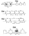
- the successive periods Tn are substantially constant, or slightly increasing when the wheel is when decelerating, or even slightly decreasing when the wheel is accelerating.
- the pressure is insufficient, there periodically occurs a period Tn of approximately twice the average value of the other pulses.
- This calculator permanently calculates the arithmetic mean of a certain number of periods and for each new period it updates if necessary the new value of the average, and calculates the ratio ⁇ n between the current value Tn of the period and the previous value Tn -1. He then interprets the variation of tK n over three successive values, noting that if the values n are constant, we can conclude that there is no underinflation and that the speed is constant, and this speed can be calculated exactly as a function of the average value of Tn, the number of teeth of the tone wheel 4 and the development of the vehicle wheel.
- the successive values n vary, if these coefficients are close to unity, an acceleration is deduced therefrom in the case where this value is less than I, and a deceleration in the case where this value is greater than 1, the computer then being able to calculate the average speed as previously and also able to calculate the value of the acceleration or deceleration as a function of these parameters. If, on the contrary, the value of ⁇ suddenly changes from a value close to one to a value that is substantially double, then it is extremely likely that it is an underinflation rather than a sudden deceleration. However, to remove the doubt, we compare according to the flow diagram of FIG.
- the computer 23 can conclude that the tire is under-inflated and trigger an alarm or display system 24 corresponding to the wheel in question, the computer naturally scanning the various wheels successively.
- the computer has for each wheel a period counter and a battery associated with the generator 22 corresponding to this wheel.
- Each interrupt signal from this generator produces the calculation of Tn and the charging of the battery which operates in a loop (right part of fig. 6) with a number of memory locations preferably corresponding to the number of teeth 6, 6a of the phonic wheels 4.
- the processor proper is unique and scans at its own pace the various batteries corresponding to the wheels, to check the operation of the sensors, check the inflation state and determine the kinetic state of the various wheels.
Landscapes
- Engineering & Computer Science (AREA)
- Mechanical Engineering (AREA)
- Measuring Fluid Pressure (AREA)
- Length Measuring Devices With Unspecified Measuring Means (AREA)
- Control Of Vehicle Engines Or Engines For Specific Uses (AREA)
- Regulating Braking Force (AREA)
Priority Applications (1)
| Application Number | Priority Date | Filing Date | Title |
|---|---|---|---|
| AT84400116T ATE23826T1 (de) | 1983-01-20 | 1984-01-20 | Reifenunterdruckfeststellvorrichtung und feststellvorrichtung des kinetischen zustands des fahrzeugs und des fahrzeugrades. |
Applications Claiming Priority (2)
| Application Number | Priority Date | Filing Date | Title |
|---|---|---|---|
| FR8300867A FR2539679A1 (fr) | 1983-01-20 | 1983-01-20 | Dispositif de detection de sous-gonflage d'un pneumatique et de mesure de l'etat cinetique de la roue d'un vehicule et du vehicule |
| FR8300867 | 1983-01-20 |
Publications (2)
| Publication Number | Publication Date |
|---|---|
| EP0117172A1 true EP0117172A1 (de) | 1984-08-29 |
| EP0117172B1 EP0117172B1 (de) | 1986-11-26 |
Family
ID=9285140
Family Applications (1)
| Application Number | Title | Priority Date | Filing Date |
|---|---|---|---|
| EP84400116A Expired EP0117172B1 (de) | 1983-01-20 | 1984-01-20 | Reifenunterdruckfeststellvorrichtung und Feststellvorrichtung des kinetischen Zustands des Fahrzeugs und des Fahrzeugrades |
Country Status (6)
| Country | Link |
|---|---|
| US (1) | US4532493A (de) |
| EP (1) | EP0117172B1 (de) |
| AT (1) | ATE23826T1 (de) |
| DE (1) | DE3461436D1 (de) |
| ES (1) | ES8500140A1 (de) |
| FR (1) | FR2539679A1 (de) |
Cited By (2)
| Publication number | Priority date | Publication date | Assignee | Title |
|---|---|---|---|---|
| EP0310776A3 (en) * | 1987-09-24 | 1990-12-19 | Wabco Westinghouse Fahrzeugbremsen Gmbh | Apparatus for signal transmission from a rotating element to a stationary element, particularly from a wheel of a vehicle to that vehicle |
| FR2669728A1 (fr) * | 1990-11-28 | 1992-05-29 | Skf France | Dispositif a capteur actif pour la surveillance de l'etat de pneumatique d'une roue de vehicule et la mesure des caracteristiques de rotation de la roue. |
Families Citing this family (9)
| Publication number | Priority date | Publication date | Assignee | Title |
|---|---|---|---|---|
| US4742712A (en) * | 1986-03-20 | 1988-05-10 | Kabushiki Kaisha Tokai Rika Denki Seisakusho | System for monitoring air pressure of motor vehicle |
| FR2706811A1 (de) * | 1993-06-25 | 1994-12-30 | Michelin & Cie | |
| EP0786361B1 (de) * | 1996-01-26 | 2002-01-02 | COMPAGNIE GENERALE DES ETABLISSEMENTS MICHELIN-MICHELIN & CIE | Verfahren zur Auswertung von Signalen einer Reifendruck-Überwachungsvorrichtung eines fahrenden Fahrzeugs |
| US6014599A (en) * | 1996-08-29 | 2000-01-11 | Denso Corporation | Tire abnormality sensor |
| IT1291171B1 (it) * | 1997-03-07 | 1998-12-29 | Skf Ind Spa | Gruppo cuscinetto con generatore di corrente integrato. |
| EP2836376B1 (de) | 2012-04-09 | 2020-03-04 | Dana Heavy Vehicle Systems Group, LLC | Reifenfüllanlage |
| US10059156B2 (en) | 2012-04-09 | 2018-08-28 | Dana Heavy Vehicle Systems Group, Llc | Hub assembly for a tire inflation system |
| US11371825B2 (en) | 2019-05-31 | 2022-06-28 | Pratt & Whitney Canada Corp. | Feedback device with differing magnetic permeability zones |
| US11333020B2 (en) | 2019-05-31 | 2022-05-17 | Pratt & Whitney Canada Corp. | Feedback device with non-axially aligned position markers |
Citations (1)
| Publication number | Priority date | Publication date | Assignee | Title |
|---|---|---|---|---|
| FR2420439A1 (fr) * | 1978-03-25 | 1979-10-19 | Wabco Fahrzeugbremsen Gmbh | Controleur de pression de pneumatique |
Family Cites Families (6)
| Publication number | Priority date | Publication date | Assignee | Title |
|---|---|---|---|---|
| US2040375A (en) * | 1935-01-14 | 1936-05-12 | George G Guthrie | Pressure alarm |
| JPS4919876A (de) * | 1972-05-13 | 1974-02-21 | ||
| US4016753A (en) * | 1976-05-07 | 1977-04-12 | United Technologies Corporation | Sub-cyclic speed and cyclic time measurements for internal combustion engine horsepower indication |
| JPS5374078A (en) * | 1976-12-14 | 1978-07-01 | Bridgestone Tire Co Ltd | Device for warning pressure reducing of inner pressure of tire |
| JPS6243432Y2 (de) * | 1979-06-15 | 1987-11-11 | ||
| JPS5929919B2 (ja) * | 1979-12-29 | 1984-07-24 | 株式会社ブリヂストン | タイヤ内圧管理装置 |
-
1983
- 1983-01-20 FR FR8300867A patent/FR2539679A1/fr active Granted
-
1984
- 1984-01-19 ES ES528993A patent/ES8500140A1/es not_active Expired
- 1984-01-20 DE DE8484400116T patent/DE3461436D1/de not_active Expired
- 1984-01-20 AT AT84400116T patent/ATE23826T1/de not_active IP Right Cessation
- 1984-01-20 US US06/572,243 patent/US4532493A/en not_active Expired - Fee Related
- 1984-01-20 EP EP84400116A patent/EP0117172B1/de not_active Expired
Patent Citations (1)
| Publication number | Priority date | Publication date | Assignee | Title |
|---|---|---|---|---|
| FR2420439A1 (fr) * | 1978-03-25 | 1979-10-19 | Wabco Fahrzeugbremsen Gmbh | Controleur de pression de pneumatique |
Cited By (2)
| Publication number | Priority date | Publication date | Assignee | Title |
|---|---|---|---|---|
| EP0310776A3 (en) * | 1987-09-24 | 1990-12-19 | Wabco Westinghouse Fahrzeugbremsen Gmbh | Apparatus for signal transmission from a rotating element to a stationary element, particularly from a wheel of a vehicle to that vehicle |
| FR2669728A1 (fr) * | 1990-11-28 | 1992-05-29 | Skf France | Dispositif a capteur actif pour la surveillance de l'etat de pneumatique d'une roue de vehicule et la mesure des caracteristiques de rotation de la roue. |
Also Published As
| Publication number | Publication date |
|---|---|
| FR2539679A1 (fr) | 1984-07-27 |
| FR2539679B1 (de) | 1985-04-19 |
| ES528993A0 (es) | 1984-10-01 |
| DE3461436D1 (en) | 1987-01-15 |
| ATE23826T1 (de) | 1986-12-15 |
| US4532493A (en) | 1985-07-30 |
| EP0117172B1 (de) | 1986-11-26 |
| ES8500140A1 (es) | 1984-10-01 |
Similar Documents
| Publication | Publication Date | Title |
|---|---|---|
| EP0117172B1 (de) | Reifenunterdruckfeststellvorrichtung und Feststellvorrichtung des kinetischen Zustands des Fahrzeugs und des Fahrzeugrades | |
| EP0988160A1 (de) | Reifen kontroll system durch beschleunigungsmessung | |
| EP0288333B1 (de) | Verfahren und Anordnung zur Kontrolle der Wirkung eines magnetischen Sensors mit variabler Reluktanz und Anwendung bei der Fahrzeugelektronik | |
| EP1094958B1 (de) | Verfahren und vorrichtung zur ermittlung einer reifenplattlaufsituation - sicherheitsträger,räder und reifen dafür hergestellt | |
| EP0664528B1 (de) | Verfahren und Vorrichtung zum Vermeiden von Betrügereien in einem mit einem Taxameter ausgerüsteten Taxi oder in einem mit einem Tachographen ausgerüsteten Lastkraftwagen | |
| WO2017063740A1 (fr) | Procede de determination de l'acceleration radiale de la roue d'un vehicule | |
| WO1998047728A1 (fr) | Insert de securite generant un signal vibratoire transversal et dispositif de detection de la mise en appui d'un pneumatique sur un insert | |
| FR2985014A1 (fr) | Procede de determination de la longueur de l'empreinte sur le sol d'un pneumatique d'une roue d'un vehicule | |
| WO2021116610A1 (fr) | Procede d'obtention de la distance parcourue par un pneumatique en roulage | |
| FR2669728A1 (fr) | Dispositif a capteur actif pour la surveillance de l'etat de pneumatique d'une roue de vehicule et la mesure des caracteristiques de rotation de la roue. | |
| EP0197813A1 (de) | Reifendruck-Kontrollvorrichtung | |
| WO2017108166A1 (fr) | Procede de configuration d'un boitier electronique monte sur une roue d'un vehicule automobile | |
| WO2014049130A1 (fr) | Dispositif de mesure de déplacement d'un véhicule roulant | |
| FR2694398A1 (fr) | Procédé et dispositifs de détection de la mise en appui d'un pneumatique sur un appui de sécurité. | |
| EP4335719A1 (de) | Vorrichtung zur erkennung von eisenbahnverkehr | |
| EP0742451B1 (de) | System zur Überwachung des Signals einer breitbandigen Messvorrichtung für Nuklearstrahlung | |
| EP0854443A1 (de) | Verfahren und Vorrichtung zum Vermeiden von Betrügereien an einem Taximeter oder einem Fahrtenschreiber | |
| FR2584348A1 (fr) | Procede de surveillance et de signalement de l'etat d'ecrasement des pneumatiques d'un vehicule en mouvement et dispositif pour sa mise en oeuvre | |
| FR3108975A1 (fr) | Procédé de diagnostic capteur vitesse/position | |
| FR3114161A1 (fr) | Procédé pour la détermination du sens de rotation d’une roue d’un véhicule automobile | |
| FR2757662A1 (fr) | Procede et dispositif pour eviter les fraudes sur un taximetre ou chronotachygraphe | |
| FR2493775A1 (fr) | Systeme de detection de seuil de pression dans un pneumatique de vehicule et vehicule equipe d'un tel systeme | |
| FR2572029A1 (fr) | Capteur de la pression de gonflage d'un pneumatique de vehicule | |
| WO2007031677A2 (fr) | Procede et systeme de determination de l'etat d'au moins un pneumatique d'une roue de vehicule | |
| FR2715490A1 (fr) | Procédé et dispositif pour éviter les fraudes sur un taxi équipé d'un taximètre ou sur un camion équipé d'un chronotachygraphe. |
Legal Events
| Date | Code | Title | Description |
|---|---|---|---|
| PUAI | Public reference made under article 153(3) epc to a published international application that has entered the european phase |
Free format text: ORIGINAL CODE: 0009012 |
|
| 17P | Request for examination filed |
Effective date: 19840126 |
|
| AK | Designated contracting states |
Designated state(s): AT BE CH DE GB IT LI NL SE |
|
| GRAA | (expected) grant |
Free format text: ORIGINAL CODE: 0009210 |
|
| AK | Designated contracting states |
Kind code of ref document: B1 Designated state(s): AT BE CH DE GB IT LI NL SE |
|
| REF | Corresponds to: |
Ref document number: 23826 Country of ref document: AT Date of ref document: 19861215 Kind code of ref document: T |
|
| ITF | It: translation for a ep patent filed | ||
| PGFP | Annual fee paid to national office [announced via postgrant information from national office to epo] |
Ref country code: AT Payment date: 19861223 Year of fee payment: 4 |
|
| REF | Corresponds to: |
Ref document number: 3461436 Country of ref document: DE Date of ref document: 19870115 |
|
| PGFP | Annual fee paid to national office [announced via postgrant information from national office to epo] |
Ref country code: NL Payment date: 19870131 Year of fee payment: 4 |
|
| PLBE | No opposition filed within time limit |
Free format text: ORIGINAL CODE: 0009261 |
|
| STAA | Information on the status of an ep patent application or granted ep patent |
Free format text: STATUS: NO OPPOSITION FILED WITHIN TIME LIMIT |
|
| 26N | No opposition filed | ||
| PG25 | Lapsed in a contracting state [announced via postgrant information from national office to epo] |
Ref country code: GB Effective date: 19890120 Ref country code: AT Effective date: 19890120 |
|
| PG25 | Lapsed in a contracting state [announced via postgrant information from national office to epo] |
Ref country code: SE Effective date: 19890121 |
|
| PG25 | Lapsed in a contracting state [announced via postgrant information from national office to epo] |
Ref country code: LI Effective date: 19890131 Ref country code: CH Effective date: 19890131 Ref country code: BE Effective date: 19890131 |
|
| BERE | Be: lapsed |
Owner name: RENAULT VEHICULES INDUSTRIELS Effective date: 19890131 |
|
| PG25 | Lapsed in a contracting state [announced via postgrant information from national office to epo] |
Ref country code: NL Effective date: 19890801 |
|
| NLV4 | Nl: lapsed or anulled due to non-payment of the annual fee | ||
| GBPC | Gb: european patent ceased through non-payment of renewal fee | ||
| REG | Reference to a national code |
Ref country code: CH Ref legal event code: PL |
|
| PG25 | Lapsed in a contracting state [announced via postgrant information from national office to epo] |
Ref country code: DE Effective date: 19891003 |
|
| EUG | Se: european patent has lapsed |
Ref document number: 84400116.4 Effective date: 19891205 |