EP4335719A1 - Vorrichtung zur erkennung von eisenbahnverkehr - Google Patents
Vorrichtung zur erkennung von eisenbahnverkehr Download PDFInfo
- Publication number
- EP4335719A1 EP4335719A1 EP23020421.6A EP23020421A EP4335719A1 EP 4335719 A1 EP4335719 A1 EP 4335719A1 EP 23020421 A EP23020421 A EP 23020421A EP 4335719 A1 EP4335719 A1 EP 4335719A1
- Authority
- EP
- European Patent Office
- Prior art keywords
- rod
- rotation
- shaft
- magnetic
- magnets
- Prior art date
- Legal status (The legal status is an assumption and is not a legal conclusion. Google has not performed a legal analysis and makes no representation as to the accuracy of the status listed.)
- Pending
Links
- 239000000523 sample Substances 0.000 claims abstract description 23
- 230000004907 flux Effects 0.000 claims description 18
- 230000006698 induction Effects 0.000 claims description 4
- 239000004020 conductor Substances 0.000 claims description 2
- 238000001514 detection method Methods 0.000 description 29
- 238000013016 damping Methods 0.000 description 11
- 230000005540 biological transmission Effects 0.000 description 4
- 238000012806 monitoring device Methods 0.000 description 4
- 238000005259 measurement Methods 0.000 description 3
- 210000000056 organ Anatomy 0.000 description 3
- IUYHQGMDSZOPDZ-UHFFFAOYSA-N 2,3,4-trichlorobiphenyl Chemical compound ClC1=C(Cl)C(Cl)=CC=C1C1=CC=CC=C1 IUYHQGMDSZOPDZ-UHFFFAOYSA-N 0.000 description 2
- 235000001674 Agaricus brunnescens Nutrition 0.000 description 2
- 239000011324 bead Substances 0.000 description 2
- 241000287107 Passer Species 0.000 description 1
- 241001249696 Senna alexandrina Species 0.000 description 1
- 241001080024 Telles Species 0.000 description 1
- 230000000694 effects Effects 0.000 description 1
- 230000007613 environmental effect Effects 0.000 description 1
- 230000005415 magnetization Effects 0.000 description 1
- 238000012423 maintenance Methods 0.000 description 1
- 239000000463 material Substances 0.000 description 1
- 238000012544 monitoring process Methods 0.000 description 1
- 230000002028 premature Effects 0.000 description 1
Images


Classifications
-
- B—PERFORMING OPERATIONS; TRANSPORTING
- B61—RAILWAYS
- B61L—GUIDING RAILWAY TRAFFIC; ENSURING THE SAFETY OF RAILWAY TRAFFIC
- B61L1/00—Devices along the route controlled by interaction with the vehicle or train
- B61L1/16—Devices for counting axles; Devices for counting vehicles
- B61L1/163—Detection devices
- B61L1/164—Mechanical
-
- B—PERFORMING OPERATIONS; TRANSPORTING
- B61—RAILWAYS
- B61L—GUIDING RAILWAY TRAFFIC; ENSURING THE SAFETY OF RAILWAY TRAFFIC
- B61L1/00—Devices along the route controlled by interaction with the vehicle or train
- B61L1/02—Electric devices associated with track, e.g. rail contacts
- B61L1/04—Electric devices associated with track, e.g. rail contacts mechanically actuated by a part of the vehicle
-
- B—PERFORMING OPERATIONS; TRANSPORTING
- B61—RAILWAYS
- B61L—GUIDING RAILWAY TRAFFIC; ENSURING THE SAFETY OF RAILWAY TRAFFIC
- B61L1/00—Devices along the route controlled by interaction with the vehicle or train
- B61L1/16—Devices for counting axles; Devices for counting vehicles
- B61L1/168—Specific transmission details
-
- B—PERFORMING OPERATIONS; TRANSPORTING
- B61—RAILWAYS
- B61L—GUIDING RAILWAY TRAFFIC; ENSURING THE SAFETY OF RAILWAY TRAFFIC
- B61L1/00—Devices along the route controlled by interaction with the vehicle or train
- B61L1/16—Devices for counting axles; Devices for counting vehicles
- B61L1/169—Diagnosis
Definitions
- the invention relates to the field of railway traffic detection systems.
- the detection systems are generally positioned in the vicinity of a rail of a railway track and conventionally comprise at least one sensor making it possible to activate an electrical contact.
- each wheel of the train moves the sensor from a high position to a low position and temporarily activates the electrical contact thus constituting a train detection signal.
- each wheel comprising a tread having a projecting edge from which a bead extends, it is the bead of each wheel which presses on the feelers.
- Each feeler is carried by a horizontal rod movable in rotation around its axis between a first angular position corresponding to the high position of the feeler and a second angular position corresponding to the low position of the feeler in such a way that pressing on the feeler causes a rotation of the rod from its first angular position to its second angular position.
- Two diametrically opposed arms are linked to the rod: one on which rests a member for returning the rod to its first angular position and one on which rests the rod of a hydraulic damping cylinder extending perpendicular to the rod to slow or delay the return of the rod to its first position.
- An aim of the invention is therefore to propose a solution making it possible to improve the reliability of rail traffic detection systems.
- a system for detecting the presence of a railway vehicle comprising a housing, a sensor outside the housing, at least one rod which carries the sensor and which is mounted in the housing to pivot between a high position and a low position of the probe, a member for slowing down the rod in rotation from the low position to the high position of the probe, a member for returning the rod to the high position of the sensor.
- the slowing down member comprises a shaft linked in rotation to the rod and movable in rotation relative to a braking member arranged to cooperate by magnetic friction with a part linked in rotation to the shaft to brake the latter.
- Magnetic friction means any braking obtained using the magnetic flux produced by at least one permanent magnet and/or at least one electromagnet. Magnetic friction being contactless friction, the Slowing down of the movement of the rod is then ensured while limiting the risks of premature wear.
- the shaft extends perpendicular to the rod and is connected to it by an angle gear.
- the detection device then has an arrangement of its different elements which is close to those of the prior art, with the shaft and the braking member substantially in the same position as the damping cylinder of the prior devices. It is then possible to have boxes of similar shape and size, and to keep the same frames for fixing the devices on the railway sleepers so that the habits of the operators responsible for installing the devices are not modified.
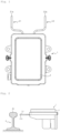
- the detection system 1 comprises a housing 2 as well as a first probe 3.1 and a second probe 3.2 extending outside the housing 2.
- the first probe 3.1 and the second probe 3.2 are generally shaped in a bar of circular section which is bent to comprise a first section and a second section substantially perpendicular to each other.
- FIG. 2 allows you to visualize the positioning of the detection system 1 relative to a rail R (here represented by a cross-sectional view) of a railway track.
- the detection system 1 is positioned in the vicinity of the rail R such that one end 3.1a of the first probe 3.1 and one end 3.2a of the second probe 3.2 are facing a mushroom Rc of the rail R.
- the detection system 1 comprises a first rod 4.1 mounted in the housing 2 to extend and pivot along an axis Y.1 here horizontal and a second rod 4.2 mounted in the housing 2 to extend and pivot along an axis Y. 2 also horizontal, the axis Y.1 being parallel to the axis Y.2.
- the first rod 5.1 has a first end carrying, projecting from the housing 2
- the second rod 4.2 has a first end carrying, projecting from the housing 2, the first section of the second feeler 3.2 of such that a movement from top to bottom and bottom to top of the probe 3.1, 3.2 causes a rotation of the rod 4.1, 4.2 and vice versa.
- the first section of each probe 3.1, 3.2 thus extends perpendicular to the axis Y.1, Y.2 and the second section of each probe 3.1, 3.2 thus extends parallel to the axis Y.1, Y. 2.
- the detection system 1 further comprises a first return member 5.1 and a second return member 5.2.
- the first return member 5.1 is an elastic blade having an end 5.1a rigidly fixed to the housing 2 and a free end portion 5.1b which bears against an arm 6.1 which extends perpendicular to the first rod 4.1 and which is secured in rotation to the first rod 4.1.
- the second return member 5.2 is an elastic blade having an end 5.2a rigidly fixed to the housing 2 and a free end portion 5.2b which bears against an arm 6.2 which extends perpendicular to the second rod 4.2 and which is secured in rotation to the second rod 4.2.
- a bevel gear 7.1, 7.2 is fixed to a second end of the first rod 4.1, 4.2 opposite the first end.
- each bevel gear 7.1, 7.2 cooperates with a bevel gear 8.1, 8.2 secured to a first shaft 9.1, 9.2 mounted in the housing 2 to pivot along an axis Z.1, Z.2 perpendicular to the axis Y.1, Y.2, that is to say the axis Z.1, Z.2 is vertical.
- a centrifugal regulator 10.1, 10.2 here is linked in rotation to the shaft 9.1, 9.2, here a magnetic brake.
- the magnetic brake can be a permanent magnet and/or electromagnet brake, such as an induction or eddy current brake.
- the magnetic brake 10.1 is here directly associated with the first shaft 9.1 carrying the bevel pinion 8.1 (but it could be associated with a secondary shaft linked in rotation with the first tree 9.1).
- the brake 10.1 comprises a wound stator 20.11 carried by the housing 2 and crossed by the first shaft 9.1, and a magnetic rotor 20.12 which is carried by the first shaft 9.1 and which is arranged in the wound stator 20.11.
- the rotor 20.12 is provided with magnetic elements, such as permanent magnets, to generate in the wound stator 20.11, when the rotor is moving, an induced current and to thus generate a force opposing the rotation of the rotor 20.12 and limiting the speed of the first shaft 9.1.
- the magnetic brake 10.1, 10.2 comprises a secondary shaft 10.11, 10.21 parallel to the first shaft 9.1, 9.2 and linked in rotation to it by sets of gears 10.12, 10.22.
- Each secondary shaft 10.11, 10.21 carries a rotor 10.13, 10.23 in the form of a disc made of an electrically conductive material which is coaxial with the secondary shaft 10.11, 10.21 and which is linked in rotation to said secondary shaft 10.11, 10.21.
- the magnetic brake 10.1, 10.2 also comprises a stator 10.14, 10.24 in the form of a disc, fixed to the housing 2 coaxially to the secondary shaft 10.11, 10.21, having a face which is oriented towards the rotor 10.13, 10.23 and which carries permanent magnets 10.14, 10.24 regularly distributed on said face.
- the permanent magnets 10.14, 10.24 have a magnetization vector which extends perpendicular to the stator 10.14, 10.24 so that they produce an axial flux capable of generating in the rotor 10.13, 10.23, when the latter pivots facing the stator 10.14, 10.24 eddy currents producing a magnetic braking torque of the rotor 10.13, 10.23.
- adjusting the angular position of the magnetic armature 10.16, 10.26 makes it possible to adjust the braking torque of the magnetic brake 10.1, 10.2 and therefore the time delay value for the return of the probe 3.1, 3.2 to the high position.
- This adjustment can be carried out manually for example by acting with a screwdriver on the tertiary shaft 10.18, 10.28 or automatically by providing a motor to rotate the tertiary shaft 10.18, 10.28 and bring the magnetic armature 10.16, 10.26 into the chosen position .
- provision can be made to stop the magnetic armature 10.16, 10.26 in any intermediate position between the two extreme positions.
- the freewheel device 11.1, 11.2 placed on the rod 4.1, 4.2 to allow the arm to descend without driving the bevel gears 7.1, 8.1, 7.2, 8.2.
- the freewheel device has a low engagement angle.
- the freewheel device 11.1, 11.2 comprises for example an outer crown having an internal toothing of 2M teeth and an inner pinion mounted coaxially in the outer crown and provided with 2N pawls which engage in the teeth of the outer ring gear in only one direction of rotation.
- the 2N pawls are diametrically opposed in pairs and are arranged so that the angle between two neighboring pawls is 180/(M x N) degrees.
- the engagement angle of the freewheel thus obtained is a maximum of 180/(M x N) degrees.
- a ratchet freewheel comprising, for example, six pairs of pawls at 31° from each other: the engagement angle of the freewheel is therefore one degree.
- first kinematic chain of the detection system 1 which comprises the first probe 3.1, the first rod 4.1, the first return member 5.1, the arm 6.1, the angle gear formed by the gears 7.1 and 8.1, the first shaft 9.1 and the centrifugal regulator 10.1.
- the first feeler 3.1 is opposite the mushroom Rc of the rail R.
- the first feeler 3.1 will change position, between a high position and a low position, due to the passage of the wheels of the railway vehicle.
- the change in position between the high position and the low position of the first probe 3.1 corresponds to a rotational movement of the first rod 4.1 along the axis X.1.
- the first rod 4.1 pivots around the axis X.1.
- the arm 6.1 will exert a force on the free end portion 5.1b of the first return member 5.1, and more precisely will lower the portion free end 5.1b and thus elastically deform the first return member 5.1.
- the free end portion 5.1b of the first return member 5.1 will return, under the effect of the elasticity of the first return member 5.1, to its position initial by pressing arm 6.1 to raise it.
- the first rod 4.1 will thus pivot around the axis Y.1 such that the first probe 3.1 leaves its low position to go towards its high position.
- the freewheel 11.1 is then engaged and the bevel gears 7.1, 8.1 will rotate the first shaft 9.1 and the rotor 10.13, 10.23 (or 20.12 in the first embodiment).
- the magnetic brake 10.1 is thus arranged to regulate the rotational movement of the first rod 4.1 (from the low position to the high position of the first feeler 3.1).
- the magnetic brake 10.1 therefore sets a duration for the rotational movement of the first rod 4.1 from the low position to the high position of the first feeler 3.1.
- the operation of the second kinematic chain of the detection system 1 - which includes the second probe 3.2, the second rod 4.2 pivoting around the axis Y.2, the second return member 8.2, the arm 6.2, the angle gear formed by the pinions 7.2 and 8.2, the shaft 9.2 and the centrifugal regulator 10.2 - is obviously similar to what has just been described for the first kinematic chain of the detection system 1.
- the detection system 1 could obviously understand only the first kinematic chain.
- the first rod 4.1 is in one piece with the first feeler 3.1.
- the second rod 4.2 is in one piece with the second probe 3.2.
- the first rod 4.1 could be a separate part from the first feeler 3.1 and/or the second rod 4.2 could be a separate part from the second feeler 3.2.
- first return member 5.1 and the second return member 5.2 are not necessarily elastic blades but could for example be helical springs mounted vertically.
- the detection system 1 could include only the first kinematic chain, that is to say only the first feeler 3.1, the first rod 4.1, the first return member 5.1, the arm 6.1, the return angle and damping member.1.
- the angle gear can be formed by toothed or friction gears.
- the shaft of the damping member can extend parallel to the rod or even coaxially with it.
- the shaft 9.1, 9.2, 10.11, 10.21 may therefore not be perpendicular to the rod 4.1, 4.2.
- the slowing down member can be carried directly by the rod 4.1, 4.2, or the shaft 9.1, 9.2.
- the openings 10.17, 10.27 can be closed by a material transparent to the magnetic field.
- the brake of the second embodiment can be arranged to operate with a radial flux, the rotor and the stator being drums engaged one in the other, and the magnetic armature a sleeve engaged between them.
- Braking torque adjustment can be obtained by modifying the air gap between the rotor and the stator.
- the braking torque adjustment device although very advantageous, is optional.
Landscapes
- Engineering & Computer Science (AREA)
- Automation & Control Theory (AREA)
- Mechanical Engineering (AREA)
- Health & Medical Sciences (AREA)
- Biomedical Technology (AREA)
- General Health & Medical Sciences (AREA)
- Measurement Of Length, Angles, Or The Like Using Electric Or Magnetic Means (AREA)
- Length Measuring Devices With Unspecified Measuring Means (AREA)
- Train Traffic Observation, Control, And Security (AREA)
- Regulating Braking Force (AREA)
- Braking Arrangements (AREA)
Applications Claiming Priority (1)
| Application Number | Priority Date | Filing Date | Title |
|---|---|---|---|
| FR2208906A FR3139312A1 (fr) | 2022-09-06 | 2022-09-06 | Dispositif de détection du trafic ferroviaire |
Publications (1)
| Publication Number | Publication Date |
|---|---|
| EP4335719A1 true EP4335719A1 (de) | 2024-03-13 |
Family
ID=83690270
Family Applications (2)
| Application Number | Title | Priority Date | Filing Date |
|---|---|---|---|
| EP23195525.3A Active EP4335720B1 (de) | 2022-09-06 | 2023-09-05 | Vorrichtung zur erkennung von eisenbahnverkehr |
| EP23020421.6A Pending EP4335719A1 (de) | 2022-09-06 | 2023-09-06 | Vorrichtung zur erkennung von eisenbahnverkehr |
Family Applications Before (1)
| Application Number | Title | Priority Date | Filing Date |
|---|---|---|---|
| EP23195525.3A Active EP4335720B1 (de) | 2022-09-06 | 2023-09-05 | Vorrichtung zur erkennung von eisenbahnverkehr |
Country Status (2)
| Country | Link |
|---|---|
| EP (2) | EP4335720B1 (de) |
| FR (1) | FR3139312A1 (de) |
Families Citing this family (1)
| Publication number | Priority date | Publication date | Assignee | Title |
|---|---|---|---|---|
| CN121008063B (zh) * | 2025-09-02 | 2026-01-27 | 中国铁路济南局集团有限公司青岛动车段 | 复兴号动车组速度智能传感器检测装置及其方法 |
Citations (2)
| Publication number | Priority date | Publication date | Assignee | Title |
|---|---|---|---|---|
| FR917319A (fr) * | 1945-07-12 | 1947-01-03 | Mors Electricite | Perfectionnements aux pédales pour chemins de fer |
| EP3885233A1 (de) * | 2020-03-23 | 2021-09-29 | Hillion, Laurent | Schienendetektor mit mechanischer zeitschaltuhr |
Family Cites Families (1)
| Publication number | Priority date | Publication date | Assignee | Title |
|---|---|---|---|---|
| SE546977C2 (en) * | 2020-06-30 | 2025-03-18 | Assa Abloy Ab | Arrangement for controlling movements of access member, access member, frame, access member system and method |
-
2022
- 2022-09-06 FR FR2208906A patent/FR3139312A1/fr active Pending
-
2023
- 2023-09-05 EP EP23195525.3A patent/EP4335720B1/de active Active
- 2023-09-06 EP EP23020421.6A patent/EP4335719A1/de active Pending
Patent Citations (2)
| Publication number | Priority date | Publication date | Assignee | Title |
|---|---|---|---|---|
| FR917319A (fr) * | 1945-07-12 | 1947-01-03 | Mors Electricite | Perfectionnements aux pédales pour chemins de fer |
| EP3885233A1 (de) * | 2020-03-23 | 2021-09-29 | Hillion, Laurent | Schienendetektor mit mechanischer zeitschaltuhr |
Also Published As
| Publication number | Publication date |
|---|---|
| EP4335720A1 (de) | 2024-03-13 |
| FR3139312A1 (fr) | 2024-03-08 |
| EP4335720B1 (de) | 2025-07-02 |
Similar Documents
| Publication | Publication Date | Title |
|---|---|---|
| EP1533465B1 (de) | Antrieb für einen Verschluss- oder Sonnenschutzvorhang und Vorrichtung mit einem derartigen Antrieb | |
| EP0814338B1 (de) | Schwenkkugellager mit eingebautem Messaufnehmer | |
| EP1444452A1 (de) | Mit geräten versehene spanneinheit und zugehöriges steuerverfahren | |
| EP4335719A1 (de) | Vorrichtung zur erkennung von eisenbahnverkehr | |
| EP3000729B1 (de) | Fahrwerk eines luftfahrzeugs | |
| FR2951965A1 (fr) | Centrifugeuse integrant des moyens tachymetriques montes dans une partie superieure de l'enceinte, en particulier montes sur le couvercle | |
| FR2888329A1 (fr) | Tachymetre pour roue d'aeronef | |
| EP0952426A1 (de) | Uhrwerk mit einem induktiven oder kapazitiven Sensor zur Detektion von mindestens einem Drehwinkel eines Zahnrades innerhalb des Uhrwerkes | |
| FR2946108A1 (fr) | Roulement instrumente, ensemble de roulement et machine electrique tournante comprenant un tel roulement ou un tel ensemble. | |
| WO2004025224A1 (fr) | Dispositif de determination du deplacement d'un arbre | |
| EP4367479A1 (de) | Bremsbelagverschleisssensor | |
| EP0443937B1 (de) | Geschwindigkeitsmessaufnehmer für den Ausgang eines Getriebes | |
| FR2993657A1 (fr) | Dispositif de mesure d'un couple transmis par un arbre de transmission de puissance avec prise en compte des variations de temperature | |
| EP2186705A1 (de) | Instrumentiertes Wälzlager für Schienenfahrzeugsachse und entsprechendes Montageverfahren | |
| EP0959362B1 (de) | Vorrichtung zur Messung einer mit der Rotation eines Organs zusammenhängenden physikalischen Grösse | |
| EP3751291A1 (de) | Anordnung aus rad und bremse eines luftfahrzeugs | |
| EP4201785A1 (de) | Überwachungseinrichtung für eisenbahn-verkehrserfassungssysteme | |
| EP0958984B1 (de) | Drehgestell für ein Schienenfahrzeug | |
| FR3001538A1 (fr) | Ensemble instrumente pour systeme tournant. | |
| EP4354108B1 (de) | System zur bestimmung eines drehmoments zwischen zwei rotierenden teilen | |
| FR3135528A1 (fr) | Tachymètre pour roue d’aéronef | |
| FR2604781A1 (fr) | Odometre pour vehicules | |
| EP0771414B1 (de) | Vorrichtung zum messen des drehmoments | |
| WO2023026003A1 (fr) | Dispositif de contrôle d'accès avec capteur gyroscopique | |
| FR2588089A1 (fr) | Capteur de champ electrique |
Legal Events
| Date | Code | Title | Description |
|---|---|---|---|
| STAA | Information on the status of an ep patent application or granted ep patent |
Free format text: STATUS: UNKNOWN |
|
| PUAI | Public reference made under article 153(3) epc to a published international application that has entered the european phase |
Free format text: ORIGINAL CODE: 0009012 |
|
| STAA | Information on the status of an ep patent application or granted ep patent |
Free format text: STATUS: THE APPLICATION HAS BEEN PUBLISHED |
|
| AK | Designated contracting states |
Kind code of ref document: A1 Designated state(s): AL AT BE BG CH CY CZ DE DK EE ES FI FR GB GR HR HU IE IS IT LI LT LU LV MC ME MK MT NL NO PL PT RO RS SE SI SK SM TR |
|
| STAA | Information on the status of an ep patent application or granted ep patent |
Free format text: STATUS: REQUEST FOR EXAMINATION WAS MADE |
|
| 17P | Request for examination filed |
Effective date: 20240909 |
|
| RBV | Designated contracting states (corrected) |
Designated state(s): AL AT BE BG CH CY CZ DE DK EE ES FI FR GB GR HR HU IE IS IT LI LT LU LV MC ME MK MT NL NO PL PT RO RS SE SI SK SM TR |