EP0117451A1 - Relais électromagnétique - Google Patents
Relais électromagnétique Download PDFInfo
- Publication number
- EP0117451A1 EP0117451A1 EP84100961A EP84100961A EP0117451A1 EP 0117451 A1 EP0117451 A1 EP 0117451A1 EP 84100961 A EP84100961 A EP 84100961A EP 84100961 A EP84100961 A EP 84100961A EP 0117451 A1 EP0117451 A1 EP 0117451A1
- Authority
- EP
- European Patent Office
- Prior art keywords
- coil
- relay
- pair
- assembly
- studs
- Prior art date
- Legal status (The legal status is an assumption and is not a legal conclusion. Google has not performed a legal analysis and makes no representation as to the accuracy of the status listed.)
- Granted
Links
- 239000000565 sealant Substances 0.000 claims description 6
- 230000000712 assembly Effects 0.000 claims description 4
- 238000000429 assembly Methods 0.000 claims description 4
- 230000000149 penetrating effect Effects 0.000 claims description 2
- 229920003002 synthetic resin Polymers 0.000 claims description 2
- 239000000057 synthetic resin Substances 0.000 claims description 2
- 230000002093 peripheral effect Effects 0.000 claims 2
- XEEYBQQBJWHFJM-UHFFFAOYSA-N Iron Chemical group [Fe] XEEYBQQBJWHFJM-UHFFFAOYSA-N 0.000 abstract description 9
- 210000000887 face Anatomy 0.000 description 5
- 238000007789 sealing Methods 0.000 description 5
- 210000001331 nose Anatomy 0.000 description 4
- 230000000694 effects Effects 0.000 description 3
- 230000001965 increasing effect Effects 0.000 description 3
- 238000009413 insulation Methods 0.000 description 3
- 238000000034 method Methods 0.000 description 3
- 238000003466 welding Methods 0.000 description 3
- 230000015556 catabolic process Effects 0.000 description 2
- 230000006835 compression Effects 0.000 description 2
- 238000007906 compression Methods 0.000 description 2
- 230000008602 contraction Effects 0.000 description 2
- 230000002708 enhancing effect Effects 0.000 description 2
- 229910000640 Fe alloy Inorganic materials 0.000 description 1
- 229910017110 Fe—Cr—Co Inorganic materials 0.000 description 1
- BGPVFRJUHWVFKM-UHFFFAOYSA-N N1=C2C=CC=CC2=[N+]([O-])C1(CC1)CCC21N=C1C=CC=CC1=[N+]2[O-] Chemical compound N1=C2C=CC=CC2=[N+]([O-])C1(CC1)CCC21N=C1C=CC=CC1=[N+]2[O-] BGPVFRJUHWVFKM-UHFFFAOYSA-N 0.000 description 1
- 229910017709 Ni Co Inorganic materials 0.000 description 1
- 229910003267 Ni-Co Inorganic materials 0.000 description 1
- 229910003262 Ni‐Co Inorganic materials 0.000 description 1
- 229910000828 alnico Inorganic materials 0.000 description 1
- 239000003795 chemical substances by application Substances 0.000 description 1
- 239000007789 gas Substances 0.000 description 1
- 238000004519 manufacturing process Methods 0.000 description 1
- 125000006850 spacer group Chemical group 0.000 description 1
- 229920001169 thermoplastic Polymers 0.000 description 1
- 239000004416 thermosoftening plastic Substances 0.000 description 1
- 238000004804 winding Methods 0.000 description 1
Images


Classifications
-
- H—ELECTRICITY
- H01—ELECTRIC ELEMENTS
- H01H—ELECTRIC SWITCHES; RELAYS; SELECTORS; EMERGENCY PROTECTIVE DEVICES
- H01H50/00—Details of electromagnetic relays
- H01H50/16—Magnetic circuit arrangements
-
- H—ELECTRICITY
- H01—ELECTRIC ELEMENTS
- H01H—ELECTRIC SWITCHES; RELAYS; SELECTORS; EMERGENCY PROTECTIVE DEVICES
- H01H51/00—Electromagnetic relays
- H01H51/22—Polarised relays
- H01H51/2272—Polarised relays comprising rockable armature, rocking movement around central axis parallel to the main plane of the armature
- H01H51/2281—Contacts rigidly combined with armature
Definitions
- This invention relates to an electromagnetic relay, particularly to a balanced armature type polarized relay having four air gaps.
- a conventional four-gap balanced armature type polarized relay includes a pair of armatures pivotally supported above or below a coil for rotation in a horizontal plane, which inevitably creates the problem that the overall vertical dimension of the relay becomes large.
- the shafts for supporting the armatures are disposed on a member which is separate from the coil, so that the relative positional accuracy between the coil and the axis of the shafts, thus between the end portions of an iron core extending through the coil and the armatures cooperating with these end portions is limited, thus involving the problem that a desired relay characteristic is difficult to reproduce.
- contact springs driven by the armatures are often restricted with respect to their disposition so that the design of multi-contacts has been difficult.
- the relay is to be sealed in a casing with high sealing effect and should exhibit high withstand voltage between the coil and the contacts.
- the present invention provides an electromagnetic relay comprising the features specified in claim 1. Accordingly, since the pair of rectangular frame-shaped armatures surround the coil and are supported for pivotal movement about a horizontal axis defined by the studs, the overall structure has a vertical dimension limited to the height of the coil assembly. Also, a multi-contact structure is easily obtained since the contact springs are positioned laterally of the coil assembly in parallel to any side of the rectangular armatures, either between them or on the outer surfaces thereof.
- a magnetic shielding between the coil and the contacts is achieved in the development of the invention as set forth in claim 8.
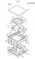
- the relay shown in Figs.. 1 to 7 comprises a casing 1 including a rectangular frame member 11 and upper and lower covers 9 and 10.
- the lower rim of the upper cover 9 and the upper rim of the lower cover 10 are each provided with a groove 19, and projecting ridges 13 fitting into the grooves 19 are provided on the top and bottom edges of the frame 11.
- the contact surfaces between the frame 11 and each of the covers 9 and 10 is thus rather large, thus providing a large area over which sealant 53 can spread. If there is a difference in the contraction rates between the frame 11 and the covers 9 and 10, either of the side surfaces of the ridge 13 will be inevitably subjected to compression by the corresponding surface of the groove 19, thereby enhancing the sealing effect.
- the frame 11 carries a pair of movable contact springs 6 and fixed contacts 8, the free end of each spring 6.having a contact portion 7 for cooperation with the respective fixed contact 8.
- a plurality of terminals 14 is embedded in the frame 11, each terminal 14 having a connecting portion extending to the outside of the frame 11, and an inner connecting portion for engagement with a corresponding connecting portion of the coil and contacts. Two of these inner connecting portions 51 of two corresponding terminals 14 are shown in Fig. 1.
- a coil assembly generally referenced by numeral 2 includes a coil 20 wound on a bobbin 22 and an iron core 21 extending through the bobbin and coil. End portions of the core 21 extend to the outside at both ends of the bobbin 22 and are each provided with a recess 25.
- the coil 20 is covered by a molded portion 23, and in applying this molded portion, the core 21 is held at the upper and lower surfaces of the core end portions, the molded portion 23 being formed integrally with a pair of studs 24 projecting laterally from both sides of the coil 20.
- the coil assembly 2 is inserted into the frame 11 in fitting projections 12 formed at the inner surfaces of the frame 11 into the grooves 25 at the end faces of the core end portions. This structure improves the mechanical strength of the frame 11 by using the iron core 21 as a central portion thereof.
- upper and lower armatures 3, 4 of flat, rectangular frame-shape are provided.
- a rectangular frame-like balancing spring 35 is mounted on the upper surface of the upper armature 3.
- a pair of permanent magnets 5 is disposed at opposite sides on the upper surface of the lower armature 4, each magnet 5 being located between a pair of connecting pins 41 extending from the lower armature 4.
- the lower surface of the upper armature 3 and the upper surface of the lower armature 4 are provided with integrally formed actuating noses 31 disposed opposite each other at an end of respective edges of the armatures.
- Bearing members 30 are provided at the centers of both sides of both armatures 3, 4 at the inner edges of their frame-shapes so as to project upwardly from the lower armature 4 and downwardly from the upper armature 3.
- the armatures 3, 4 are disposed so as to surround the coil assembly 2, which itself has been mounted in the frame 11.
- the connecting pins 41 projecting upwardly from the lower armature 4 are fitted into bores 32 in the upper armature 3 thereby connecting the two armatures 3, 4 so that they are maintained parallel to each other.
- the two pairs of upper and lower bearing members 30 provided at both armatures 3, 4 sandwich the pair of studs 24 extending from the molded portion 23 of the coil assembly 2, and the pair of permanent magnets 5 abut with their upper surfaces against the lower surface of the upper armature 3.
- the thus completed armature assembly is supported for pivotal movement about the horizontal axis defined by the pair of studs 24.
- the contact springs 6 are sandwiched between the opposing actuating noses 31 provided at the inner surfaces of the upper and lower armatures 3, 4. Also,-the contact units formed by the contact springs 6 and the fixed contacts 8 are disposed within a shielded space S enclosed by the permanent magnets 5 and the upper and lower armatures 3, 4 as shown in Fig. 4.
- the coil 20 and the contact units are magnetically shielded from each other so that surges from the contact side (output side) are prevented from influencing the coil side (input side), in other words, the electronic circuit at the input side is protected against being damaged by surges occurring at the output side.
- the molded portion 23 of the coil assembly 2 is not shown.
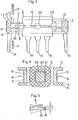
- the casing is closed by placing the upper and lower covers 9, 10 on the respective edges of the frame 11 with sealant being disposed between the contacting surfaces of these casing portions as explained above.
- the coil 20 has its wire ends connected to coil connecting portions 50 which project laterally from the ends of the core 21 extending from the coil.
- coil connecting portions 50 which project laterally from the ends of the core 21 extending from the coil.
- a double-coil has been assumed, so that there are four coil connecting portions 50.
- these coil connecting portions 50 come into engagement with portions 51 which are the inner ends of terminals 14.
- the engaging condition between these connecting portions 50 and 51 is shown in detail in Fig. 6.
- ribs 52 are formed integrally with said upper and lower covers 9, 10 so as to project inwardly with each rib 52 of the upper cover 9 facing a corresponding rib of the lower cover 10 at a position corresponding to the connecting portions 50 and 51.
- Each fixed contact 8 is mounted on a pole plate 15 which has a pair of lugs 16 projecting from both sides at the central portion of the plate 15, as specifically shown in Fig. 2. These lugs 16 are embedded in a portion of the frame 11 and connected to a respective one of the terminals 14.
- the fixed contact 8 is mounted at a front end of the plate 15 at a position in which it opposes the contact portion 7 provided on the contact spring 6, whereas the rear end of the plate 15 projects beyond the tip of the spring 6.
- an adjusting tool 17 may be used to press on the rear end of the plate 15 from above or below to rotate the plate 15 about a horizontal axis defined by the lugs 16 thereby varying the vertical position of the fixed contact 8, as shown in Fig. 5.
- the studs 24 supporting the armature assembly are integral with the molded portion 23 covering the coil 20 so that the ironcore 21 penetrating through the coil 20 and the studs 24 are in a fixed position relatively to each other and form a common block to be conveniently assembled and inserted into the relay frame 11.
- the relative position between the upper and lower surfaces provided at both ends of the iron core 21, which serve as the pole faces, and the end surfaces of the armatures 3 and 4 cooperating with these pole faces is thus reproduced with high accuracy, so that stable relay characteristics are obtained.
- the pair of armatures 3, 4 and the contact units 6 are disposed at the lateral sides of the coil 20, so that the vertical dimension of the entire mechanism may be restricted to the height of the coil 20. Accordingly, a relay of thin structure is devised, without imposing restrictions on the coil design which may thus be wound with maximum efficiency.
- the contacts 7, 8 are not affected by gases or moisture from the coil winding.
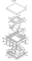
- the modified embodiment of the invention shown in Fig. 8 differs from that described above in that the bearing members 30 are formed near the outer edges of only the lower armature 4 outside the permanent magnets 5.
- the bearing members 30, the connecting pins 41 and the actuating noses 31 are integrally molded with the armatures 3, 4.
- Bearing studs 24 1 of semi-circular cross-section extend between opposite inner surfaces of the frame member 11 and webs 46 integrally disposed within the frame member 11.
- the studs 24' are supported at both of their ends so that they have high strength and dimensional stability.
- the existence of the webs 46 and their connection to the respective inner surfaces of the frame member 11 through the studs 24' increase the strength and dimensional stability of the frame member 11.
- the upper and lower armatures 3, 4 are pivotally supported by placing the frame-like balancing spring 35 at two sides thereof on the projections 12 molded to opposite inner sides of the frame member 11, and bringing the semi-circular cut-outs in the pair of bearing members 30 on the lower armature 4 in contact with the semi-circular lower bearing surfaces of the studs 24'.
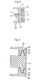
- Figs. 9 and 10 show another way of connecting the permanent magnets 5 between the upper and lower armatures 3, 4, which structure may be employed in either of the relays according to Figs. 1 to 8.
- the permanent magnets 5 serve as spacers defining the interval between the upper and lower armatures 3, 4 and employ iron alloy magnets of the alnico series (Fe-Ni-Co) or the Fe-Cr-Co series.
- the mutually facing inner surfaces of the armatures 3, 4 are provided with sockets 36 of thermoplastic synthetic resin providing a wall for surrounding the mounting faces of the permanent magnets 5.
- FIG. 11 and 12 differs from those described above in that the flat, rectangular frame-shaped upper and lower armatures 3, 4 are interconnected at two opposite ends by brackets 18 each of which has an integrally molded stud 24".
- the studs 24" define a pivot axis for the armature assembly which extends along the axis of the coil 20.
- the studs 24" are supported by bearing members (not shown) which may be provided at opposite inner walls of the frame member 11.
- two permanent magnets 5 are disposed between the upper and lower armatures 3, 4 to magnetize them with opposite polarities. Both end portions of the iron core 21' extending from the coil 20 are bent perpendicularly to the coil axis to opposite sides.
- Contact springs (not shown) driven by the armature assembly are disposed parallel to any side of the armatures outside the same. If the armatures are dimensioned so as to extend beyond the permanent magnets 5, as shown in phantom lines in Fig..12, the contact springs may be disposed between the armatures in a manner similar to that shown in Fig. 4.
Landscapes
- Physics & Mathematics (AREA)
- Electromagnetism (AREA)
- Electromagnets (AREA)
Priority Applications (1)
| Application Number | Priority Date | Filing Date | Title |
|---|---|---|---|
| AT84100961T ATE20789T1 (de) | 1983-01-31 | 1984-01-31 | Elektromagnetisches relais. |
Applications Claiming Priority (4)
| Application Number | Priority Date | Filing Date | Title |
|---|---|---|---|
| JP1414483A JPS59139529A (ja) | 1983-01-31 | 1983-01-31 | バランスアマチユア型リレ− |
| JP14144/83 | 1983-01-31 | ||
| JP3233883A JPS59158042A (ja) | 1983-02-28 | 1983-02-28 | 有極リレ− |
| JP32338/83 | 1983-02-28 |
Publications (2)
| Publication Number | Publication Date |
|---|---|
| EP0117451A1 true EP0117451A1 (fr) | 1984-09-05 |
| EP0117451B1 EP0117451B1 (fr) | 1986-07-16 |
Family
ID=26350045
Family Applications (1)
| Application Number | Title | Priority Date | Filing Date |
|---|---|---|---|
| EP19840100961 Expired EP0117451B1 (fr) | 1983-01-31 | 1984-01-31 | Relais électromagnétique |
Country Status (2)
| Country | Link |
|---|---|
| EP (1) | EP0117451B1 (fr) |
| DE (1) | DE3460282D1 (fr) |
Cited By (4)
| Publication number | Priority date | Publication date | Assignee | Title |
|---|---|---|---|---|
| EP0272409A1 (fr) * | 1986-10-31 | 1988-06-29 | Alcatel SEL Aktiengesellschaft | Relais plat polarisé |
| EP0204346A3 (en) * | 1985-06-06 | 1988-09-21 | Omron Tateisi Electronics Co. | Low profile electromagnetic relay suitable for being mounted to printed circuit board |
| EP0865060A3 (fr) * | 1997-02-13 | 2001-02-07 | Tyco Electronics Logistics AG | Relais électromagnétique |
| CN114902365A (zh) * | 2019-12-11 | 2022-08-12 | 泰科电子奥地利有限责任公司 | 用于线圈的芯部 |
Citations (4)
| Publication number | Priority date | Publication date | Assignee | Title |
|---|---|---|---|---|
| DE2537462A1 (de) * | 1974-08-22 | 1976-03-11 | Matsushita Electric Works Ltd | Elektromagnetisches schuetz |
| FR2314576A1 (fr) * | 1975-06-11 | 1977-01-07 | Matsushita Electric Works Ltd | Relais a lame |
| FR2435799A1 (fr) * | 1978-09-08 | 1980-04-04 | Omron Tateisi Electronics Co | Relais electromagnetique |
| EP0040778A1 (fr) * | 1980-05-16 | 1981-12-02 | Omron Tateisi Electronics Co. | Dispositif électromagnétique polarisé |
-
1984
- 1984-01-31 DE DE8484100961T patent/DE3460282D1/de not_active Expired
- 1984-01-31 EP EP19840100961 patent/EP0117451B1/fr not_active Expired
Patent Citations (4)
| Publication number | Priority date | Publication date | Assignee | Title |
|---|---|---|---|---|
| DE2537462A1 (de) * | 1974-08-22 | 1976-03-11 | Matsushita Electric Works Ltd | Elektromagnetisches schuetz |
| FR2314576A1 (fr) * | 1975-06-11 | 1977-01-07 | Matsushita Electric Works Ltd | Relais a lame |
| FR2435799A1 (fr) * | 1978-09-08 | 1980-04-04 | Omron Tateisi Electronics Co | Relais electromagnetique |
| EP0040778A1 (fr) * | 1980-05-16 | 1981-12-02 | Omron Tateisi Electronics Co. | Dispositif électromagnétique polarisé |
Cited By (6)
| Publication number | Priority date | Publication date | Assignee | Title |
|---|---|---|---|---|
| EP0204346A3 (en) * | 1985-06-06 | 1988-09-21 | Omron Tateisi Electronics Co. | Low profile electromagnetic relay suitable for being mounted to printed circuit board |
| US4831348A (en) * | 1985-06-06 | 1989-05-16 | Omron Tateisi Electronics Co. | Low profile electromagnetic relay to printed circuit board |
| EP0272409A1 (fr) * | 1986-10-31 | 1988-06-29 | Alcatel SEL Aktiengesellschaft | Relais plat polarisé |
| US4772865A (en) * | 1986-10-31 | 1988-09-20 | Standard Elektrik Lorenz Ag | Flat-type polarized relay |
| EP0865060A3 (fr) * | 1997-02-13 | 2001-02-07 | Tyco Electronics Logistics AG | Relais électromagnétique |
| CN114902365A (zh) * | 2019-12-11 | 2022-08-12 | 泰科电子奥地利有限责任公司 | 用于线圈的芯部 |
Also Published As
| Publication number | Publication date |
|---|---|
| DE3460282D1 (en) | 1986-08-21 |
| EP0117451B1 (fr) | 1986-07-16 |
Similar Documents
| Publication | Publication Date | Title |
|---|---|---|
| US3993971A (en) | Electromagnetic relay | |
| JP4190379B2 (ja) | 複合型電磁継電器 | |
| CN103339705B (zh) | 电磁继电器 | |
| CN101283428B (zh) | 继电器 | |
| EP0186160B1 (fr) | Relais électromagnétique | |
| EP0727803B1 (fr) | Relais polarisé | |
| EP0117451B1 (fr) | Relais électromagnétique | |
| US4570138A (en) | Balanced armature type relay | |
| US6780055B2 (en) | Terminal structure of high frequency signal transmitting part | |
| JPH081543Y2 (ja) | 電磁継電器 | |
| US3921107A (en) | Electro-magnetic relay | |
| US4437078A (en) | Polarized electromagnetic device | |
| US4482875A (en) | Polarized electromagnetic midget relay | |
| EP0040778B1 (fr) | Dispositif électromagnétique polarisé | |
| JP4470837B2 (ja) | リレー | |
| JPS59114721A (ja) | トランスフア形電磁継電器 | |
| JPS6260786B2 (fr) | ||
| CN101283430B (zh) | 继电器 | |
| JP2773236B2 (ja) | 電磁継電器 | |
| CA1037532A (fr) | Relais electromagnetique | |
| JPH0747779Y2 (ja) | 有極リレー | |
| JPH0427654B2 (fr) | ||
| JP2893602B2 (ja) | 電磁継電器 | |
| JPH01276527A (ja) | 電磁継電器 | |
| JPH03134930A (ja) | 電磁継電器 |
Legal Events
| Date | Code | Title | Description |
|---|---|---|---|
| PUAI | Public reference made under article 153(3) epc to a published international application that has entered the european phase |
Free format text: ORIGINAL CODE: 0009012 |
|
| AK | Designated contracting states |
Designated state(s): AT CH DE FR GB IT LI |
|
| 17P | Request for examination filed |
Effective date: 19840730 |
|
| GRAA | (expected) grant |
Free format text: ORIGINAL CODE: 0009210 |
|
| AK | Designated contracting states |
Kind code of ref document: B1 Designated state(s): AT CH DE FR GB IT LI |
|
| REF | Corresponds to: |
Ref document number: 20789 Country of ref document: AT Date of ref document: 19860815 Kind code of ref document: T |
|
| REF | Corresponds to: |
Ref document number: 3460282 Country of ref document: DE Date of ref document: 19860821 |
|
| ITF | It: translation for a ep patent filed | ||
| ET | Fr: translation filed | ||
| PLBI | Opposition filed |
Free format text: ORIGINAL CODE: 0009260 |
|
| 26 | Opposition filed |
Opponent name: STANDARD ELEKTRIK LORENZ AG Effective date: 19870410 |
|
| PLBN | Opposition rejected |
Free format text: ORIGINAL CODE: 0009273 |
|
| STAA | Information on the status of an ep patent application or granted ep patent |
Free format text: STATUS: OPPOSITION REJECTED |
|
| 27O | Opposition rejected |
Effective date: 19890417 |
|
| REG | Reference to a national code |
Ref country code: CH Ref legal event code: PUE Owner name: SDS-RELAIS AG |
|
| ITPR | It: changes in ownership of a european patent |
Owner name: CESSIONE;SDS - RELAIS AG |
|
| REG | Reference to a national code |
Ref country code: GB Ref legal event code: 732 |
|
| REG | Reference to a national code |
Ref country code: FR Ref legal event code: TP |
|
| ITTA | It: last paid annual fee | ||
| REG | Reference to a national code |
Ref country code: CH Ref legal event code: PFA Free format text: EURO-MATSUSHITA ELECTRIC WORKS AKTIENGESELLSCHAFT |
|
| PGFP | Annual fee paid to national office [announced via postgrant information from national office to epo] |
Ref country code: FR Payment date: 19911218 Year of fee payment: 9 |
|
| PGFP | Annual fee paid to national office [announced via postgrant information from national office to epo] |
Ref country code: GB Payment date: 19920117 Year of fee payment: 9 |
|
| PGFP | Annual fee paid to national office [announced via postgrant information from national office to epo] |
Ref country code: DE Payment date: 19920222 Year of fee payment: 9 |
|
| PGFP | Annual fee paid to national office [announced via postgrant information from national office to epo] |
Ref country code: CH Payment date: 19920227 Year of fee payment: 9 Ref country code: AT Payment date: 19920227 Year of fee payment: 9 |
|
| PG25 | Lapsed in a contracting state [announced via postgrant information from national office to epo] |
Ref country code: LI Effective date: 19930131 Ref country code: GB Effective date: 19930131 Ref country code: CH Effective date: 19930131 Ref country code: AT Effective date: 19930131 |
|
| GBPC | Gb: european patent ceased through non-payment of renewal fee |
Effective date: 19930131 |
|
| PG25 | Lapsed in a contracting state [announced via postgrant information from national office to epo] |
Ref country code: FR Effective date: 19930930 |
|
| REG | Reference to a national code |
Ref country code: CH Ref legal event code: PL |
|
| REG | Reference to a national code |
Ref country code: FR Ref legal event code: ST |
|
| PG25 | Lapsed in a contracting state [announced via postgrant information from national office to epo] |
Ref country code: DE Effective date: 19931201 |