EP0186160B1 - Relais électromagnétique - Google Patents
Relais électromagnétique Download PDFInfo
- Publication number
- EP0186160B1 EP0186160B1 EP85116376A EP85116376A EP0186160B1 EP 0186160 B1 EP0186160 B1 EP 0186160B1 EP 85116376 A EP85116376 A EP 85116376A EP 85116376 A EP85116376 A EP 85116376A EP 0186160 B1 EP0186160 B1 EP 0186160B1
- Authority
- EP
- European Patent Office
- Prior art keywords
- electromagnet
- contact
- armature
- relay
- core
- Prior art date
- Legal status (The legal status is an assumption and is not a legal conclusion. Google has not performed a legal analysis and makes no representation as to the accuracy of the status listed.)
- Expired - Lifetime
Links
Images



Classifications
-
- H—ELECTRICITY
- H01—ELECTRIC ELEMENTS
- H01H—ELECTRIC SWITCHES; RELAYS; SELECTORS; EMERGENCY PROTECTIVE DEVICES
- H01H50/00—Details of electromagnetic relays
- H01H50/02—Bases; Casings; Covers
- H01H50/06—Bases; Casings; Covers having windows; Transparent cases or covers
-
- H—ELECTRICITY
- H01—ELECTRIC ELEMENTS
- H01H—ELECTRIC SWITCHES; RELAYS; SELECTORS; EMERGENCY PROTECTIVE DEVICES
- H01H50/00—Details of electromagnetic relays
- H01H50/02—Bases; Casings; Covers
- H01H50/026—Details concerning isolation between driving and switching circuit
-
- H—ELECTRICITY
- H01—ELECTRIC ELEMENTS
- H01H—ELECTRIC SWITCHES; RELAYS; SELECTORS; EMERGENCY PROTECTIVE DEVICES
- H01H51/00—Electromagnetic relays
- H01H51/22—Polarised relays
- H01H51/2227—Polarised relays in which the movable part comprises at least one permanent magnet, sandwiched between pole-plates, each forming an active air-gap with parts of the stationary magnetic circuit
-
- H—ELECTRICITY
- H01—ELECTRIC ELEMENTS
- H01H—ELECTRIC SWITCHES; RELAYS; SELECTORS; EMERGENCY PROTECTIVE DEVICES
- H01H50/00—Details of electromagnetic relays
- H01H50/16—Magnetic circuit arrangements
- H01H50/36—Stationary parts of magnetic circuit, e.g. yoke
- H01H2050/365—Stationary parts of magnetic circuit, e.g. yoke formed from a single sheet of magnetic material by punching, bending, plying
-
- H—ELECTRICITY
- H01—ELECTRIC ELEMENTS
- H01H—ELECTRIC SWITCHES; RELAYS; SELECTORS; EMERGENCY PROTECTIVE DEVICES
- H01H50/00—Details of electromagnetic relays
- H01H50/16—Magnetic circuit arrangements
- H01H50/36—Stationary parts of magnetic circuit, e.g. yoke
Definitions
- the present invention relates to an electromagnetic relay, and more particularly to an electromagnetic relay including a mount base provided with an insulation partition for separating an electromagnet from a contact assembly, and starts from DE-A-3 202 043.
- Electromagnetic relays particularly relays requiring a high contact rating within a small-sized casing are known to have a partition wall dividing the interior of a relay casing into two spaces, one for mounting an electromagnet and the other for a contact assembly.
- the relay construction having the above partition for separating the electromagnet from the contact assembly becomes more essential for designing a miniature relay in which components are densely-packed with a maximum insulation resistance between the electromagnet and the contact assembly.
- Prior relays having the above partition are disclosed, for example, in US-A-4,101,856, 4,302,742, and 4,339,735, in all of which the partition extends along the length of the electromagnet for separation thereof from the contact assembly.
- the partition employed in each prior art relay must have a slot or opening within its length for passing therethrough a card or like actuating member which operatively connects the electromagnet to the contact assembly in order to actuate the switching operation of the contact assembly in response to the energization of the electromagnet.
- the partition fails to achieve complete insulation between the contact assembly and the electromagnet within the entire length of the electromagnet, and therefore the slot or opening is likely to form between the electromagnet and the contact assembly a shortcut leakage path through which a possible arcing originating from the contact assembly may extend to and damage the electromagnet.
- the partition of the prior relays therefore, the electrical insulation is interrupted at a portion of the partition, thereby considerably reducing the effectiveness of the partition and providing but unsatisfactory insulation, which is a hindrance to designing a miniature relay having a high contact rating in which magnetic and electric components are required to be dense-packed at a maximum insulation resistance.
- DE-A-3 202 043 discloses an electromagnetic relay with the features included in the first part of claim 1. There, the free end of the movable contact is driven by the relay armature via an actuator plate. The actuator plate is slidably received in a channel which forms a communication between the coil space containing the electromagnet and the switching space containing the contact assembly. The above-indicated problem resulting from a shortcut leakage path between the electromagnet and the contact assembly is not solved satisfactorily in this known relay design.
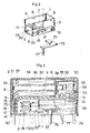
- an electromagnetic relay which comprises a mount base 1 for mounting an electromagnet 30, an armature 50, and a contact assembly 70.
- the mount base 1 is made of electrically insulative material such as molded plastics in the form of a casing opened at its top and one longitudinal end face.
- a shield cover 2 of like insulative material fits snugly over the mount base or casing 1 to close the top and the end face.
- the casing 1 has a rectangular bottom wall 3, a pair of opposite side walls 4 and 5 extending upwardly from the lateral sides of the bottom wall 3, and an end wall 6 extending upwardly from the longitudinal end of the bottom wall 3 and joining said side walls 4 and 5 at its lateral ends.
- a partition 7 integrally extends from the end wall 6 between the opposed side walls 4 and 5 in parallel relation with the bottom wall 3 so as to divide the interior of casing 1 into a coil space 8 for mounting said electromagnet 30 and a switching space 9 for said contact assembly 70.
- Said partition 7 extends a distance greater than the length of the electromagnet 30 and terminates at an edge which is recessed with respect to the longitudinal open end of the casing 1 to leave thereat a recess 10 through which said coil space 8 is communicated with said switching space 9.
- Said electromagnet 30 comprises a U-shaped yoke 31 having a pair of parallel legs 32 connected by a web 33, a core 34 extending from the web 33 in parallel relation to the yoke legs 32, and a winding 36 wound around the core 34 to magnetize the free ends of the yoke legs 32 to a polarity opposite to that of the core 34.
- the winding 36 is carried around a coil bobbin 37 molded from electrically insulative plastics material which is embraced between the yoke legs 32 and is supported thereon by means of said core 34 being inserted through the coil bobbin 37 to be connected to the web 33 of the yoke 31.
- One of the yoke legs 32 is provided at its free end with a bridge member 38 which extends integrally from upper end thereof.
- the bridge member 38 is bent at a right angle toward the other yoke leg 32 and is then clamped thereto by any known technique for rigid connection between the free ends of the yoke legs 32, reinforcing the yoke 31 to have good dimension stability against possible shocks which may be applied thereto at the time of assembling the relay.
- the bridge member 38 is thus spaced upwardly from an enlarged flat pole end 35 of the core 34 and serves as a pole member of the same polarity as the yoke legs 32 but of opposite polarity to the pole end 35.
- the electromagnet 30 thus constructed is fixed in place within said coil space 8 with protrusions 39 formed on the yoke legs 32 being snapped in complementary eyelets 11 formed in the upper end portion of the side walls 4 and 5 of the casing 1.
- a plurality of coil terminal lugs 40 provided at one longitudinal end of said coil bobbin 37 extend downwardly through individual vertical slots 13 formed in an upstanding section 12 at the juncture of the end wall 6 with the partition 7 to project outwardly of the bottom wall 3 of the casing 1, as best shown in Figs. 3 and 4, for connection with an external relay control circuit.
- Extending horizontally from the other longitudinal end of the coil bobbin 37 are a pair of support arms 41 for pivotally supporting the armature 50.
- each support arm 41 has in its free end a bearing hole 42 with an open slit 43.
- Said armature 50 includes a mold block 51 of electrically insulative plastic material which holds a pair of pole plates 52 and 53 and a permanent magnet 54.
- the pole plates 52 and 53 have their rear end portions embedded in the mold block 51 with the permanent magnet 54 interposed therebetween so as to be magnetized to opposite polarity.
- Projecting transversely from either side of the mold block 51 is a pivot pin 55 which is snapped into each of said bearing holes 42 through said open slit 43 so that the armature 50 is held by said support arms 41 for pivotal movement about a horizontal axis perpendicular to the longitudinal axis of the electromagnet 30.
- the armature 50 has its major portion received within said coil space 8 adjacent the longitudinal end of the electromagnet 30 and is coupled thereto in such a way that said pole end 35 of the core 34 extends between the pole plates 52 and 53 and at the same time that the upper pole plate 52 extends between the pole end 35 and the bridge member 38.
- the armature 50 is driven to rotate in a direction indicated by an arrow in the figure to an operative position where the upper pole plate 52 is attracted to the pole end 35 of the core 34 when the electromagnet 30 is energized by a given polarity of voltage.
- the armature 50 responds to rotate in the opposite direction into a stable position of Fig. 3 where the upper pole plate 52 is attracted to the bridge member 38 as the lower pole plate 53 to the pole end 35 of the core 34 for completing the magnetic circuit of the permanent magnet 54 and is retained at this stable position until the electromagnet 30 is again energized by the given polarity of voltage.
- the relay of this embodiment is a polarized relay having a monostable armature operation.
- Integrally formed with the mold block 51 of the armature 50 is a generally L-shaped card 56 which passes around the open end of said partition 7 or through said recess 10 to extend into the switching space 9 for connection of the armature 50 with the contact assembly 70.
- the card 56 is formed at the free end of its horizontal segment with a catch slit 57 for coupling with a movable contact spring 71 of the contact assembly 70.
- the contact assembly 70 comprises the movable contact spring 71 and a pair of fixed contact plates 72 and 73 both being of generally L-shaped but having different lengths.
- Each of the fixed contact plates 72 and 73 carries at its one end each one of contact tips 74 and 75 and is formed at the other end with each one of downwardly extending terminal lugs 76 and 77.
- Said fixed contact plates 72 and 73 can be fixed to the casing 1 from the exterior thereof in a manner shown in Fig. 4.
- the fixed contact plates 72 and 73 have their contact tip carrying portions inserted into the switching space 9 through respective ports 14 and 15 formed in the side walls 4 and 5 so as to locate the contact tips 74 and 75 in vertically spaced relation within the switching space 9, and are held in place by their side leg portions being press fitted into longitudinal grooves 16 and 17 formed in the outer surfaces of the side walls 4 and 5.
- the ports 14 and 15 are formed at portion below said partition 7 and adjacent to said end wall 6 such that the contact tips 74 and 75 or switching contact portion of the contact assembly 70 is disposed deep inside of the switching space 9 so as to be apart a maximum distance from said recess 10 leading to the coil space 8 where the electromagnet 30 is mounted, thus substantially insulating the electromagnet 30 from the switching contact portion by the partition 7, end wall 6 and the side walls 4 and 5.
- Said terminal lugs 76 and 77 of the fixed contact plates 74 and 75 are fitted respectively in vertical grooves 18 and 19 continuous with the longitudinal ends of said lengthwise grooves 16 and 17 opposite to the ports 14 and 15 so that they extend downwardly and outwardly of the bottom wall 3.
- Said movable contact spring 71 is in the form of an elongate blade having its one end portion connected to a contact base 80 with a terminal lug 79 and having on the upper and lower sides of the other end portion contact tips 81 which are engageable with the respective one of the contact tips 74 and 75 of said fixed contact plates 72 and 73.
- the movable contact spring 71 can be also fixed to the casing from the exterior thereof in a manner shown in Fig. 4.
- the movable contact spring 71 is introduced through the open end of the casing 1 into said switching space 9 and is secured to the casing 1 by inserting the lateral edges of said contact base 80 in a press-fitted manner into end slits 20 formed in the inner surface of the side walls 4 and 5 adjacent the bottom wall 3 with the terminal lug 79 extending outwardly through a notch 22 in the bottom wall 3 of the casing 1.
- the movable contact spring 71 is operatively connected to the armature 50 and is movable therewith in response to the energization and deenergization of the electromagnet 30.
- Said switching contact portion including the contact tip 81 of the movable contact spring 71 is accessible through either port 14 or 15 from the exterior of the casing 1 and therefore can be adjusted its contact gap by the use of a suitable adjusting tool insertable through the port 14 or 15.
- the ports 14 and 15 are closed by the shield cover 2 fitted over the casing 1.
- FIGs. 5 to 10 there is shown an electromagnet relay in accordance with an embodiment of the present invention which is similar in construction to the relay described above except for a contact assembly 90 and for the detailed configuration of the armature 50.
- the like numerals are employed to designate like parts.
- the contact assembly 90 includes two sets of contact units each comprising a movable contact spring 91 and a pair of fixed contact plate 92 and 93.
- the fixed contact plates 92 and 93 of each contact unit are introduced into the switching space 9 of the casing 1 by inserting the carrier portion for contact tips 94 and 95 through each of the ports 14 and 15 in the side walls 4 and 5 and are fixed to the casing 1 by their side legs press-fitted into longitudinal grooves 24 in the outer surface of each of the side walls 14 and 15.
- terminal lugs 96 and 97 integral with the fixed contact plates 92 and 93 of each contact unit are received in vertical grooves 25 continuous with the longitudinal grooves 24 so as to extend downwardly of the bottom wall 3.
- the contact tips 94 and 95 of the fixed contact plates 92 and 93 of each contact unit are vertically aligned with a contact tip 98 of each movable contact spring 91 interposed therebetween, these contact tips defining switching the contact portion of each contact unit.
- the two sets of contact units thus constructed and received in the switching space 9 are transversely spaced and have their switching contact portions separated from each other by a separator 27 depending from said partition 7 and continuous with the end wall 3, as shown in Fig. 10.
- Each of the movable contact springs 91 is in the form of elongate blade having a terminal lug 99 at its one end and having on the upper and lower sides of the other end said contact tips 98 which are engageable with the respective one of the contact tips 94 and 95 of the fixed contact plate 92 and 93.
- Each movable contact spring 91 extends longitudinally within the switching space 9 and is fixed to the casing 1 by inserting the upper end of the terminal lug 99 in a press-fit manner into a vertical slit 26 formed in the open end side of the bottom wall 3 adjacent each of the side walls 4 and 5.
- the armature 50 of this embodiment is further formed in each of the lateral sides of the horizontally extending section of the card 56 with a furrow 60 into which the side edge of the rear half portion of each movable contact spring 91 is loosely fitted.
- the furrow 60 is formed at a portion near the free end of the card 56 with a wedge portion 61 at which portion said movable contact spring 91 is clamped to the card 56 for transmitting the force therethrough from the armature 50 to the movable contact spring 91.
- a V-shaped catch opening 62 is formed at the extremity of each furrow 60 for easily catching the edge portion of the movable contact spring 91 at the time of inserting the horizontal section of the card 56 into the switching space 9 for connection with the movable contact springs 91.
- the movable contact springs 91 act as a horizontal guide for easy insertion of the card 56 into the switching space 9 of the casing 1.
- the coupling between the armature 50 and the contact assembly 90 is such that, when the armature 50 is brought into its stable position of Fig. 6 in response to deenergization of the electromagnet 30, the movable contact spring 91 of each contact unit is kept in contacting engagement with the upper fixed contact plate 92 and out of contacting engagement with the lower fixed contact plate 93.
- the movable contact spring 91 is urged by the card 56 into contacting engagement with the lower fixed contact plate 93 and out of contacting engagement with the upper fixed contact plate 92.
- Said armature 50 is further formed on both sides of the mold block 51 with integral skirts 64 which are located below said recess 10 at the open end of the partition 7 and extend toward the side walls 4 and 5 of the casing 1 with its front portion kept in close relation to the end of the partition 7, as shown in Figs. 6 and 9.
- a pair of flaps 28 are integrally formed with the side walls 4 and 5 at portions just above the rear ends of the movable contact springs 91 but below said recess 10.
- Each flaps 28 extends inwardly toward the underside of each skirt 64 in such a manner as to be in overlapping relation therewith, thus leaving between the armature 50 and the side walls 4 and 5 only a zig-zag paths which serve to considerably elongate the communication path extending through said recess 10 between the switching space 9 and the coil space 8.
- the electromagnet 100 shown in Fig. 11 is identical in construction to that of the previous embodiment except that another lower bridge member 44 is added to extend over the free ends of the yoke legs 32 in vertically spaced relation to the upper bridge member 38.
- the like numerals are employed to designate like parts as in the previous embodiment.
- the other constructions of the relay are as above.
- the added lower bridge member 44 is also made of magnetic material serving as a pole member of the same polarity as the upper bridge member 38 and of opposite polarity to the pole end 35 of the core 34. These bridge members 38 and 44 are equally vertically spaced from the pole end 35 interposed therebetween.
- the electromagnet 100 thus constructed is magnetically coupled to the armature 50 of like construction (although only the permanent magnet 54 and the pole plates 52 and 53 thereof are illustrated in the figures) in such a manner that each of the pole plates 52 and 53 extends between the pole end 35 and each of the upper and lower bridge members 38 and 44.
- the armature 50 in response to the electromagnet 100 being energized by the voltage of opposite polarity, is driven to rotate into opposite positions at each of which the one of the pole plates 52 and 53 is attracted to the pole end 35 of the core 34 and at the same time the other pole plate is attracted to each of the bridge members 38 and 44.
- the armature 50 Upon deenergization of the electromagnet 100, the armature 50 is kept at each of the above positions as the magnetic circuit of the permanent magnet 54 is completed through the pole plates 52 and 53, core 34, yoke legs 32 and 33, and through each of the bridge members 38 and 44. Consequently, the armature 50 can have the two stable positions, thereby giving a bistable switching characteristic to the contact assembly (not shown) to be connected to the armature 50 in the same manner as above.
- Said lower bridge member 44 may be a separate piece to be clamped at its both ends to the free ends of the yoke legs 32 or may be a continuous piece which extends integrally from one of the yoke legs 32 and which is to be bent toward the other yoke leg and is then clamped thereto.
Landscapes
- Physics & Mathematics (AREA)
- Electromagnetism (AREA)
- Electromagnets (AREA)
Claims (7)
- Relais électromagnétique comportant
un support de montage (1) en matériau électriquement isolant possédant un compartiment de bobine (8) pour recevoir un électro-aimant (30), un compartiment de commutation (9) pour recevoir un ensemble de contacts (90), et une cloison isolante (7) séparant le compartiment de bobine (8) du compartiment de commutation (9), et
une armature (50) couplée magnétiquement audit électro-aimant (30) et reliée fonctionnellement à un contact mobile (91) dudit ensemble de contacts (90),
caractérisé en ce que
ladite cloison (7) s'étend sur toute la longueur de l'électro-aimant (30) et posséde sur un bord terminal un évidement (10) par l'intermédiaire duquel ledit compartiment de bobine (8) et ledit compartiment de commutation (9) communiquent entre eux,
en ce que ladite armature (50) est formée sur ses côtés latéraux avec des jupes (64) de matériau électriquement isolant s'étendant vers des parois latérales (4, 5) dudit support de montage (1), et
en ce que lesdites parois latérales (4, 5) sont formées sur des parties adjacentes audit évidement (10) avec des flasques (28) s'étendant vers l'intérieur, recouvrant chacun l'une desdites jupes respectives (64) pour fermer sensiblement l'évidement (10) en vue d'un isolement dudit électro-aimant (30) des parties électriquement conductrices dudit ensemble de contacts (90). - Relais selon la revendication 1, dans lequel ladite armarture (50) comprend une carte (56) en matériau électriquement isolant qui entoure le bord terminal de ladite cloison (7) pour s'étendre dans ledit compartiment de commutation (9) pour un engagement dudit contact mobile (91).
- Relais selon la revendication 1 ou 2, dans lequel ledit électro-aimant (30) comporte une culasse en forme de U (31) ayant ses branches opposées (32) réunies par une âme (33), un noyau (34) s'étendant depuis ladite âme (33) parallèlement auxdites branches (32), un bobinage (36) enroulé autour du noyau (34), et un élément de pont (38) reliant entre elles de façon rigide les extrémités desdites branches (32).
- Relais selon la revendication 3, dans lequel ledit élément de pont (38) sert de pièce polaire de polarité opposée à celle dudit noyau (34) et est espacé de l'extrémité libre (35) du noyau (34) dans une direction perpendiculaire au plan desdites branches (32) de la culasse, et dans lequel ladite armature (50) comprend une paire de plaques polaires (52, 53) espacées dans une direction perpendiculaire au plan desdites branches (32) de la culasse et magnétisées selon des polarités opposées par un aimant permanant (54) interposé entre elles, l'une desdites plaques polaires (52) s'étendant entre le noyau (34) et l'élément de pont (38) pour assurer une position d'armature stable lorsque ladite première plaque polaire (52) est attirée vers ledit élément de pont (38) lors d'une désexcitation de l'électro-aimant (30).
- Relais selon la revendication 4, dans lequel les extrémités libres desdites branches de culasse (32) sont reliées entre elles par un second élément de pont (44) servant de pièce polaire de polarité opposée à celle du noyau (34), les deux éléments de pont (38, 44) étant espacés l'un de l'autre dans une direction perpendiculaire au plan desdites branches de culasse (32), l'extrémité libre (35) dudit noyau (34) étant interposée entre eux, et
dans lequel chacune desdites plaques polaires d'armature (52, 53) s'étend entre ledit noyau (34) et l'un desdits éléments de pont respectifs (38, 44) pour assurer deux positions d'armature stables dans lesquelles chaque plaque polaire (52, 53) est attirée vers l'élément de pont adjacent (38, 44) lors de la désexcitation de l'électro-aimant (100). - Relais selon l'une quelconque des revendications 1 à 5, dans lequel au moins l'une desdites parois latérales (4, 5) est réalisée avec un orifice (14, 15) à travers lequel ledit contact mobile (71, 91) est accessible depuis l'extérieur dudit support de montage (1).
- Relais selon l'une quelconque des revendications 1 à 6, dans lequel ledit ensemble de contacts(90) comprend deux groupes de contacts comportant chacun un contact mobile (91), et au moins un contact fixe (92, 93), et
dans lequel ladite cloison (7) est réalisée avec un séparateur (27) s'étendant depuis celle-ci pour diviser ledit compartiment de commutation (9) en compartiments distincts pour recevoir chacun l'un desdits groupes de contacts.
Priority Applications (1)
| Application Number | Priority Date | Filing Date | Title |
|---|---|---|---|
| AT85116376T ATE77173T1 (de) | 1984-12-22 | 1985-12-20 | Elektromagnetisches relais. |
Applications Claiming Priority (4)
| Application Number | Priority Date | Filing Date | Title |
|---|---|---|---|
| JP271529/85 | 1984-12-22 | ||
| JP59271529A JPS61148803A (ja) | 1984-12-22 | 1984-12-22 | 電磁石装置用ヨ−ク |
| JP59278585A JPS61151939A (ja) | 1984-12-24 | 1984-12-24 | リレ− |
| JP278585/84 | 1984-12-24 |
Publications (3)
| Publication Number | Publication Date |
|---|---|
| EP0186160A2 EP0186160A2 (fr) | 1986-07-02 |
| EP0186160A3 EP0186160A3 (en) | 1988-08-24 |
| EP0186160B1 true EP0186160B1 (fr) | 1992-06-10 |
Family
ID=26549755
Family Applications (1)
| Application Number | Title | Priority Date | Filing Date |
|---|---|---|---|
| EP85116376A Expired - Lifetime EP0186160B1 (fr) | 1984-12-22 | 1985-12-20 | Relais électromagnétique |
Country Status (6)
| Country | Link |
|---|---|
| US (1) | US4688010A (fr) |
| EP (1) | EP0186160B1 (fr) |
| KR (1) | KR890005314B1 (fr) |
| AU (1) | AU565608B2 (fr) |
| CA (1) | CA1249000A (fr) |
| DE (1) | DE3586200T2 (fr) |
Families Citing this family (16)
| Publication number | Priority date | Publication date | Assignee | Title |
|---|---|---|---|---|
| EP0189921B1 (fr) * | 1985-01-31 | 1989-08-02 | Nec Corporation | Relais électromagnétique |
| JP2605786B2 (ja) * | 1988-03-09 | 1997-04-30 | オムロン株式会社 | 電磁継電器 |
| DE3908442A1 (de) * | 1989-03-15 | 1990-10-11 | Eberle Gmbh | Elektromagnetisches schaltgeraet |
| ATE121560T1 (de) * | 1989-07-20 | 1995-05-15 | Omron Tateisi Electronics Co | Anschlusskontaktform für elektromagnetisches relais. |
| CH677162A5 (fr) * | 1989-10-30 | 1991-04-15 | Carlo Cavazzi Electromatic Ag | |
| EP0501951B1 (fr) * | 1989-11-16 | 1993-10-13 | Siemens Aktiengesellschaft | Relais electromagnetique |
| CA2018344C (fr) * | 1989-12-07 | 1995-12-12 | Yoichi Yokoyama | Contacts de relais electromagnetique resistants a une liaison par fusion |
| DE59303588D1 (de) * | 1992-05-15 | 1996-10-02 | Siemens Ag | Polarisiertes leistungsrelais |
| DE19606883C1 (de) * | 1996-02-23 | 1997-04-30 | Schrack Components Ag | Elektromagnetisches Relais mit kombinierter Kontakt- und Rückstellfeder |
| DE19606884C1 (de) * | 1996-02-23 | 1997-04-30 | Schrack Components Ag | Elektromagnetisches Relais |
| JP3590738B2 (ja) * | 1999-04-27 | 2004-11-17 | Necトーキン株式会社 | 電磁継電器およびその調整方法と組立方法 |
| JP2003115248A (ja) * | 2001-10-01 | 2003-04-18 | Tyco Electronics Ec Kk | 電磁継電器 |
| JP5991778B2 (ja) * | 2012-04-19 | 2016-09-14 | 富士通コンポーネント株式会社 | 電磁継電器 |
| CN104813570A (zh) * | 2012-12-14 | 2015-07-29 | 武汉领普科技有限公司 | 永磁发电装置 |
| JP2014165152A (ja) * | 2013-02-27 | 2014-09-08 | Fujitsu Component Ltd | 電磁継電器 |
| DE102014103247A1 (de) * | 2014-03-11 | 2015-09-17 | Tyco Electronics Austria Gmbh | Elektromagnetisches Relais |
Family Cites Families (26)
| Publication number | Priority date | Publication date | Assignee | Title |
|---|---|---|---|---|
| US2965954A (en) * | 1956-02-06 | 1960-12-27 | Cook Electric Co | Method of assembling a relay |
| US2951134A (en) * | 1957-10-03 | 1960-08-30 | Lazich Branko | Electrical relays |
| US3377519A (en) * | 1963-12-26 | 1968-04-09 | Allen Bradley Co | Magnetically latched switch |
| GB1200321A (en) * | 1967-01-16 | 1970-07-29 | Lucas Industries Ltd | Electromagnetic relays |
| DE1639417B1 (de) * | 1968-02-29 | 1970-11-12 | Hans Sauer | Elektromagnetisches Mehrkontaktrelais |
| US3553612A (en) * | 1969-05-21 | 1971-01-05 | Gen Electric | Miniature relay with double air gap magnetic circuit |
| US3553613A (en) * | 1969-07-23 | 1971-01-05 | Square D Co | Magnet and movable contact support structure for a multiple contact electromagnetically actuated switch |
| US3668578A (en) * | 1970-06-03 | 1972-06-06 | Westinghouse Air Brake Co | Lightweight electromagnetic relay |
| DE2105130A1 (de) * | 1971-02-04 | 1972-08-17 | Sihn Jr Kg Wilhelm | Abdeckhaube mit Trennkammern für Relais |
| DE2218494B1 (de) * | 1972-04-17 | 1973-10-11 | Siemens Ag, 1000 Berlin U. 8000 Muenchen | Elektromagnetisches Relais |
| DE2407057C3 (de) * | 1974-02-14 | 1979-04-26 | Siemens Ag, 1000 Berlin Und 8000 Muenchen | Elektromagnetisches Schaltgerät |
| DE2614942A1 (de) * | 1976-04-07 | 1977-10-20 | Ernst Duerr | Elektromagnetisches kleinschaltrelais |
| US4136321A (en) * | 1977-04-04 | 1979-01-23 | Standex International Corporation | Reed relay assembly and the method of making same |
| DE2723220C2 (de) * | 1977-05-23 | 1979-08-02 | Siemens Ag, 1000 Berlin Und 8000 Muenchen | Polarisiertes elektromagnetisches Miniaturrelais |
| JPS54119657A (en) * | 1978-03-08 | 1979-09-17 | Idec Izumi Corp | Small relay |
| DE2912800C2 (de) * | 1979-03-30 | 1985-04-25 | Siemens AG, 1000 Berlin und 8000 München | Elektromagnetisches Relais für hohe Schaltleistungen |
| DE7909135U1 (de) * | 1979-03-30 | 1979-07-05 | Siemens Ag, 1000 Berlin Und 8000 Muenchen | Elektromagnetisches Relais für hohe Schaltleistungen |
| CH649170A5 (de) * | 1979-04-18 | 1985-04-30 | Rausch & Pausch | Magnetankerhalterung in einem relais. |
| JPS5615522A (en) * | 1979-07-18 | 1981-02-14 | Matsushita Electric Works Ltd | Electromagnetic relay |
| AT384497B (de) * | 1981-04-30 | 1987-11-25 | Sds Relais Ag | Polarisiertes relais |
| DE3149816C2 (de) * | 1981-12-16 | 1986-09-04 | Diehl GmbH & Co, 8500 Nürnberg | Polarisiertes Relais |
| DE8201576U1 (de) * | 1982-01-23 | 1993-01-21 | Bach Gmbh + Co, 7100 Heilbronn | Relais |
| DE3240800A1 (de) * | 1982-11-04 | 1984-05-10 | Hans 8024 Deisenhofen Sauer | Elektromagnetisches relais |
| JPS59166349U (ja) * | 1983-04-22 | 1984-11-07 | オムロン株式会社 | 有極電磁リレ− |
| CH663290A5 (de) * | 1983-11-28 | 1987-11-30 | Sprecher & Schuh Ag | Elektromagnetisches schaltgeraet. |
| DE3347602A1 (de) * | 1983-12-30 | 1985-07-11 | Siemens AG, 1000 Berlin und 8000 München | Polarisiertes elektromagnetisches relais |
-
1985
- 1985-11-21 US US06/800,393 patent/US4688010A/en not_active Expired - Fee Related
- 1985-12-13 AU AU51220/85A patent/AU565608B2/en not_active Ceased
- 1985-12-20 DE DE8585116376T patent/DE3586200T2/de not_active Expired - Lifetime
- 1985-12-20 CA CA000498253A patent/CA1249000A/fr not_active Expired
- 1985-12-20 EP EP85116376A patent/EP0186160B1/fr not_active Expired - Lifetime
- 1985-12-21 KR KR1019850009681A patent/KR890005314B1/ko not_active Expired
Also Published As
| Publication number | Publication date |
|---|---|
| KR890005314B1 (ko) | 1989-12-20 |
| AU5122085A (en) | 1986-06-26 |
| CA1249000A (fr) | 1989-01-17 |
| EP0186160A3 (en) | 1988-08-24 |
| AU565608B2 (en) | 1987-09-24 |
| DE3586200T2 (de) | 1992-12-10 |
| KR860005415A (ko) | 1986-07-23 |
| EP0186160A2 (fr) | 1986-07-02 |
| DE3586200D1 (de) | 1992-07-16 |
| US4688010A (en) | 1987-08-18 |
Similar Documents
| Publication | Publication Date | Title |
|---|---|---|
| EP0186160B1 (fr) | Relais électromagnétique | |
| EP0197391B1 (fr) | Relais électromagnétique polarisé | |
| EP0196022B2 (fr) | Dispositif de commande électromagnétique polarisé | |
| US5515019A (en) | Polarized power relay | |
| CA1257632A (fr) | Relais electromagnetique | |
| KR940009305B1 (ko) | 전자 계전기 | |
| EP0390372B1 (fr) | Relais électromagnétique polarisé | |
| HK1005608B (en) | Polarized electromagnetic relay | |
| CA1133032A (fr) | Relais electromagnetique a transfert constitue d'une bobine entourant le boitier et d'une armature a contacts mobiles aux deux extremites | |
| US4482875A (en) | Polarized electromagnetic midget relay | |
| EP0169542B1 (fr) | Relais électromagnétique polarisé | |
| EP0183867B1 (fr) | Relais pour circuits à haute fréquence | |
| EP0462841B1 (fr) | Rélais électromagnétique polarisé du type étroit | |
| CA1037532A (fr) | Relais electromagnetique | |
| US4609896A (en) | Polarized electromagnetic miniature relay | |
| CA1224512A (fr) | Relais pour circuits haute frequence | |
| JPH05274983A (ja) | リレーの構造 | |
| JPH088046B2 (ja) | 有極リレ− | |
| GB2149211A (en) | Electrical relays | |
| JPH0676720A (ja) | リレーの構造 | |
| JPS6311732B2 (fr) | ||
| JPS6362059B2 (fr) |
Legal Events
| Date | Code | Title | Description |
|---|---|---|---|
| PUAI | Public reference made under article 153(3) epc to a published international application that has entered the european phase |
Free format text: ORIGINAL CODE: 0009012 |
|
| AK | Designated contracting states |
Kind code of ref document: A2 Designated state(s): AT BE CH DE FR GB IT LI LU NL SE |
|
| PUAL | Search report despatched |
Free format text: ORIGINAL CODE: 0009013 |
|
| AK | Designated contracting states |
Kind code of ref document: A3 Designated state(s): AT BE CH DE FR GB IT LI LU NL SE |
|
| 17P | Request for examination filed |
Effective date: 19880908 |
|
| 17Q | First examination report despatched |
Effective date: 19900927 |
|
| RAP1 | Party data changed (applicant data changed or rights of an application transferred) |
Owner name: EURO-MATSUSHITA ELECTRIC WORKS AKTIENGESELLSCHAFT |
|
| GRAA | (expected) grant |
Free format text: ORIGINAL CODE: 0009210 |
|
| ITF | It: translation for a ep patent filed | ||
| AK | Designated contracting states |
Kind code of ref document: B1 Designated state(s): AT BE CH DE FR GB IT LI LU NL SE |
|
| REF | Corresponds to: |
Ref document number: 77173 Country of ref document: AT Date of ref document: 19920615 Kind code of ref document: T |
|
| REF | Corresponds to: |
Ref document number: 3586200 Country of ref document: DE Date of ref document: 19920716 |
|
| ET | Fr: translation filed | ||
| PLBE | No opposition filed within time limit |
Free format text: ORIGINAL CODE: 0009261 |
|
| STAA | Information on the status of an ep patent application or granted ep patent |
Free format text: STATUS: NO OPPOSITION FILED WITHIN TIME LIMIT |
|
| 26N | No opposition filed | ||
| EPTA | Lu: last paid annual fee | ||
| EAL | Se: european patent in force in sweden |
Ref document number: 85116376.6 |
|
| PGFP | Annual fee paid to national office [announced via postgrant information from national office to epo] |
Ref country code: BE Payment date: 19950906 Year of fee payment: 11 |
|
| PGFP | Annual fee paid to national office [announced via postgrant information from national office to epo] |
Ref country code: FR Payment date: 19951018 Year of fee payment: 11 |
|
| PGFP | Annual fee paid to national office [announced via postgrant information from national office to epo] |
Ref country code: LU Payment date: 19951101 Year of fee payment: 11 |
|
| PGFP | Annual fee paid to national office [announced via postgrant information from national office to epo] |
Ref country code: DE Payment date: 19951108 Year of fee payment: 11 |
|
| PGFP | Annual fee paid to national office [announced via postgrant information from national office to epo] |
Ref country code: SE Payment date: 19951113 Year of fee payment: 11 Ref country code: AT Payment date: 19951113 Year of fee payment: 11 |
|
| PGFP | Annual fee paid to national office [announced via postgrant information from national office to epo] |
Ref country code: CH Payment date: 19951114 Year of fee payment: 11 |
|
| PGFP | Annual fee paid to national office [announced via postgrant information from national office to epo] |
Ref country code: GB Payment date: 19951211 Year of fee payment: 11 |
|
| PGFP | Annual fee paid to national office [announced via postgrant information from national office to epo] |
Ref country code: NL Payment date: 19951230 Year of fee payment: 11 |
|
| PG25 | Lapsed in a contracting state [announced via postgrant information from national office to epo] |
Ref country code: LU Free format text: LAPSE BECAUSE OF NON-PAYMENT OF DUE FEES Effective date: 19961220 Ref country code: GB Effective date: 19961220 Ref country code: AT Effective date: 19961220 |
|
| PG25 | Lapsed in a contracting state [announced via postgrant information from national office to epo] |
Ref country code: SE Effective date: 19961221 |
|
| PG25 | Lapsed in a contracting state [announced via postgrant information from national office to epo] |
Ref country code: LI Effective date: 19961231 Ref country code: CH Effective date: 19961231 Ref country code: BE Effective date: 19961231 |
|
| BERE | Be: lapsed |
Owner name: EURO-MATSUSHITA ELECTRIC WORKS A.G. Effective date: 19961231 |
|
| PG25 | Lapsed in a contracting state [announced via postgrant information from national office to epo] |
Ref country code: NL Effective date: 19970701 |
|
| GBPC | Gb: european patent ceased through non-payment of renewal fee |
Effective date: 19961220 |
|
| REG | Reference to a national code |
Ref country code: CH Ref legal event code: PL |
|
| PG25 | Lapsed in a contracting state [announced via postgrant information from national office to epo] |
Ref country code: FR Effective date: 19970829 |
|
| NLV4 | Nl: lapsed or anulled due to non-payment of the annual fee |
Effective date: 19970701 |
|
| PG25 | Lapsed in a contracting state [announced via postgrant information from national office to epo] |
Ref country code: DE Effective date: 19970902 |
|
| EUG | Se: european patent has lapsed |
Ref document number: 85116376.6 |
|
| REG | Reference to a national code |
Ref country code: FR Ref legal event code: ST |