EP0117785A2 - Valve de retenue à vide - Google Patents
Valve de retenue à vide Download PDFInfo
- Publication number
- EP0117785A2 EP0117785A2 EP84400199A EP84400199A EP0117785A2 EP 0117785 A2 EP0117785 A2 EP 0117785A2 EP 84400199 A EP84400199 A EP 84400199A EP 84400199 A EP84400199 A EP 84400199A EP 0117785 A2 EP0117785 A2 EP 0117785A2
- Authority
- EP
- European Patent Office
- Prior art keywords
- vacuum
- valve
- check valve
- orifice
- output port
- Prior art date
- Legal status (The legal status is an assumption and is not a legal conclusion. Google has not performed a legal analysis and makes no representation as to the accuracy of the status listed.)
- Granted
Links
Images
Classifications
-
- F—MECHANICAL ENGINEERING; LIGHTING; HEATING; WEAPONS; BLASTING
- F16—ENGINEERING ELEMENTS AND UNITS; GENERAL MEASURES FOR PRODUCING AND MAINTAINING EFFECTIVE FUNCTIONING OF MACHINES OR INSTALLATIONS; THERMAL INSULATION IN GENERAL
- F16K—VALVES; TAPS; COCKS; ACTUATING-FLOATS; DEVICES FOR VENTING OR AERATING
- F16K15/00—Check valves
- F16K15/14—Check valves with flexible valve members
- F16K15/148—Check valves with flexible valve members the closure elements being fixed in their centre
-
- F—MECHANICAL ENGINEERING; LIGHTING; HEATING; WEAPONS; BLASTING
- F02—COMBUSTION ENGINES; HOT-GAS OR COMBUSTION-PRODUCT ENGINE PLANTS
- F02P—IGNITION, OTHER THAN COMPRESSION IGNITION, FOR INTERNAL-COMBUSTION ENGINES; TESTING OF IGNITION TIMING IN COMPRESSION-IGNITION ENGINES
- F02P5/00—Advancing or retarding ignition; Control therefor
- F02P5/04—Advancing or retarding ignition; Control therefor automatically, as a function of the working conditions of the engine or vehicle or of the atmospheric conditions
- F02P5/05—Advancing or retarding ignition; Control therefor automatically, as a function of the working conditions of the engine or vehicle or of the atmospheric conditions using mechanical means
- F02P5/10—Advancing or retarding ignition; Control therefor automatically, as a function of the working conditions of the engine or vehicle or of the atmospheric conditions using mechanical means dependent on fluid pressure in engine, e.g. combustion-air pressure
- F02P5/103—Advancing or retarding ignition; Control therefor automatically, as a function of the working conditions of the engine or vehicle or of the atmospheric conditions using mechanical means dependent on fluid pressure in engine, e.g. combustion-air pressure dependent on the combustion-air pressure in engine
-
- Y—GENERAL TAGGING OF NEW TECHNOLOGICAL DEVELOPMENTS; GENERAL TAGGING OF CROSS-SECTIONAL TECHNOLOGIES SPANNING OVER SEVERAL SECTIONS OF THE IPC; TECHNICAL SUBJECTS COVERED BY FORMER USPC CROSS-REFERENCE ART COLLECTIONS [XRACs] AND DIGESTS
- Y10—TECHNICAL SUBJECTS COVERED BY FORMER USPC
- Y10S—TECHNICAL SUBJECTS COVERED BY FORMER USPC CROSS-REFERENCE ART COLLECTIONS [XRACs] AND DIGESTS
- Y10S137/00—Fluid handling
- Y10S137/907—Vacuum-actuated valves
-
- Y—GENERAL TAGGING OF NEW TECHNOLOGICAL DEVELOPMENTS; GENERAL TAGGING OF CROSS-SECTIONAL TECHNOLOGIES SPANNING OVER SEVERAL SECTIONS OF THE IPC; TECHNICAL SUBJECTS COVERED BY FORMER USPC CROSS-REFERENCE ART COLLECTIONS [XRACs] AND DIGESTS
- Y10—TECHNICAL SUBJECTS COVERED BY FORMER USPC
- Y10T—TECHNICAL SUBJECTS COVERED BY FORMER US CLASSIFICATION
- Y10T137/00—Fluid handling
- Y10T137/2496—Self-proportioning or correlating systems
- Y10T137/2544—Supply and exhaust type
- Y10T137/2546—Vacuum or suction pulsator type [e.g., milking machine]
Definitions
- This invention relates to vacuum valves in general and more particularly to a vacuum check valve with fluid bleed to a reference pressure.
- the invention disclosed herein is intended to be used in the vacuum line between the vacuum source and vacuum operated devices to assure that vapors and contaminants never reach the vacuum operated devices.
- the vacuum check valve of the present invention comprises a single umbrella valve responding to vacuum differences between the input and output of the check valve to direct the output line to feed the vacuum source or to receive reference air through a bleed passage and there is no diaphragm operated poppet valve.
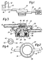
- FIGURE 1 a schematic view of a vacuum operated control system as may be used on an internal combustion engine as found in a motor vehicle.
- the source of the vacuum is the intake manifold 10, as shown in FIGURE 1, and the vacuum is taken from a throttle body 12 having a rotatable throttle valve 14 controlling the fuel/air mixture flowing into the intake manifold 10.
- a vacuum line 16 Extending away from the throttle body 12 is a vacuum line 16 which is connected to the input 18 of the vacuum check valve 20 of the present invention.
- a vacuum operated device 24 Connected to the output 22 of the vacuum check valve 20 is a vacuum operated device 24 which may be an emission control device or any vacuum operated control valve typically found in a motor vehicle.
- a reference pressure is supplied to the bottom of the vacuum check valve 20 which reference pressure is typically atmospheric pressure and will be used as hereinafter described.
- the source of vacuum is intake manifold vacuum and is taken from the throttle body 12 below the throttle blade 14 and will, during idle or deceleration operations, be at a high vacuum due to the operation of the engine.
- the vacuum is drawn off the throttle body 12 through a vacuum line 16 to a vacuum operated device 24. It is the purpose of the vacuum check valve 20 to prevent the flow of vapors or other contaminants from the manifold 10 to the vacuum operated device 24.
- FIGURE 2 there is shown a bottom plan view of the vacuum check valve 20 of the present invention.
- This view illustrates a plastic cap 26 which is snapped on to the lower portion of the valve 20.
- the cap 26 contains a plurality of openings 28 around its periphery, or in the alternative, in the bottom of the cap 26 to allow a reference pressure, which is typically atmospheric pressure, to be supplied to the valve 20.
- the cap 26, as shown in FIGURE 3 holds or retains a second filter 30 in the valve 20 to remove all foreign particles from the reference pressure.
- the body or housing of the valve 20 of the present invention is typically formed from two or more molded plastic members 32 and 34 and as shown comprise an upper 32 and a lower 34 member which together form the housing. The cap 26 is snapped on the lower member 34 of the valve 20.
- FIGURE 3 is a cross-sectional view of the valve 20 illustrating the several elements of the valve
- the housing of the valve 20 forms two chambers 36 and 38 interconnected through an orifice 40.
- the input port 18 of the check valve 20 is connected through a first filter 42 to the first chamber 36 and is adapted to be connected to the source of the vacuum which, in FIGURE 1, is in the throttle body 12 of the engine.
- the output port 22 of the valve 20 is connected through a third filter 44 to the same chamber 36 of the valve 20.
- the output port 22 is connected from the valve 20 to one or more vacuum operated devices 24 in the system.
- the function of the third filter 44 is to remove contaminants in the air from the device 24 to keep the inner surfaces in the chamber 36 clean to prevent fouling of the valve operation.
- an umbrella valve Positioned in the orifice 40 between the two chambers 36 and 38 of the check valve 20 is an umbrella valve which has an umbrella-shaped top 46 and an elongated stem 48 axially extending from the underside thereof.
- the elongated stem 48 extends through the orifice 40 into the second chamber 38 in the valve 20.
- the second chamber 38 is enclosed by the cap 26.
- the openings of the cap 28 supply air to the valve 20 through the second filter 30 to remove and clean the air before it reaches the orifice 40.
- the stem 48 of the umbrella valve extends through the orifice 40 and has on the bottom side of the orifice 40, as shown in FIGURE 3, an orifice closing member 50 which operates to seal the orifice 40 in the second chamber 38.
- the umbrella-shaped top 46 extends over the third filter 44 in the output port 22 of the valve 20 and effectively, under certain conditions, closes the output port 22 from any effects of the input port 18.
- two bleed passages 54 are shown connecting the volume under the umbrella-shaped top 46 of the umbrella valve and the output port 22 to the orifice 40 when the umbrella valve is closed.
- the umbrella valve has a large circular surface connected to the underside thereof, which seals the top of the orifice 40 under certain operating conditions which will hereinafter be explained.
- the vacuum check valve 20 controls the flow of fluid, and in particular air, between the input 18 and the output 22 ports.
- the vacuum operated device 24 operates to evacuate the air pressure therein by having air flow through the output port 22 of the check valve 20, the third filter 44 and into the volume under the umbrella-shaped top 46 of the umbrella valve. Since there is a high vacuum at the input port 18, the umbrella-shaped top 46 lifts off the inner surface of the check valve 20 and allows the air to flow around the umbrella-shaped top 46 through the first filter 42 in the input port 18 to the vacuum source in the manifold 10.
- the umbrella-shaped top collapses or flattens sealing its edges against the inner surface of the first chamber 36 of the valve 20 adjacent the orifice 40 and the large circular surface 52 seals the top of the orifice 40. If the third filter 44 did not remove contaminants from the air flowing from the device, such contaminants would foul the valve and prevent the umbrella-shaped top 46 from sealing.
- the stem 48 moves causing the orifice closing member 50 to move away from the bottom of the orifice 40 allowing the orifice to be opened to the reference pressure.
- the pair of bleed passages 54 are positioned adjacent the orifice 40.
- the size and number of bleed passages 54 depends upon the speed of decay desired and the capacity of the vacuum to be reduced in the vacuum operated device 24.
Landscapes
- Engineering & Computer Science (AREA)
- General Engineering & Computer Science (AREA)
- Mechanical Engineering (AREA)
- Physics & Mathematics (AREA)
- Fluid Mechanics (AREA)
- Chemical & Material Sciences (AREA)
- Combustion & Propulsion (AREA)
- Check Valves (AREA)
- Details Of Valves (AREA)
Applications Claiming Priority (2)
| Application Number | Priority Date | Filing Date | Title |
|---|---|---|---|
| US06/462,180 US4499916A (en) | 1983-01-31 | 1983-01-31 | Vacuum check valve |
| US462180 | 1990-01-08 |
Publications (3)
| Publication Number | Publication Date |
|---|---|
| EP0117785A2 true EP0117785A2 (fr) | 1984-09-05 |
| EP0117785A3 EP0117785A3 (en) | 1987-04-01 |
| EP0117785B1 EP0117785B1 (fr) | 1989-08-16 |
Family
ID=23835464
Family Applications (1)
| Application Number | Title | Priority Date | Filing Date |
|---|---|---|---|
| EP19840400199 Expired EP0117785B1 (fr) | 1983-01-31 | 1984-01-30 | Valve de retenue à vide |
Country Status (6)
| Country | Link |
|---|---|
| US (1) | US4499916A (fr) |
| EP (1) | EP0117785B1 (fr) |
| AU (1) | AU568623B2 (fr) |
| BR (1) | BR8400439A (fr) |
| CA (1) | CA1224379A (fr) |
| DE (1) | DE3479435D1 (fr) |
Cited By (1)
| Publication number | Priority date | Publication date | Assignee | Title |
|---|---|---|---|---|
| EP3449782A1 (fr) * | 2017-08-28 | 2019-03-06 | BSH Hausgeräte GmbH | Corps de valve et machine à café munie de ce dernier |
Families Citing this family (14)
| Publication number | Priority date | Publication date | Assignee | Title |
|---|---|---|---|---|
| DE19625768B4 (de) * | 1996-06-27 | 2009-04-16 | Pierburg Gmbh | Dünnwandiges Saugrohr für eine Brennkraftmaschine |
| US5896882A (en) * | 1996-06-27 | 1999-04-27 | Northrop Grumman Corporation | Pressure control valve |
| SE9802123D0 (sv) * | 1998-06-15 | 1998-06-15 | Siemens Elema Ab | Riktningsventil |
| US6447491B1 (en) * | 1999-06-18 | 2002-09-10 | Genzyme Corporation | Rolling seal suction pressure regulator, apparatus and system for draining a body cavity and methods related thereto |
| US7703702B2 (en) * | 2004-04-07 | 2010-04-27 | Illinois Tool Works Inc. | Pneumatically operated device having check valve vent and method for making same |
| US7296782B2 (en) * | 2004-10-01 | 2007-11-20 | Halkey-Roberts Corporation | Dome check valve |
| JP5110828B2 (ja) * | 2006-08-29 | 2012-12-26 | キヤノン株式会社 | 圧力制御弁、圧力制御弁の製造方法、圧力制御弁を搭載した燃料電池システム及びその圧力制御方法 |
| US20110186151A1 (en) * | 2010-02-04 | 2011-08-04 | Bernard Joseph Sparazynski | Check valve |
| KR101371761B1 (ko) * | 2012-12-26 | 2014-03-07 | 기아자동차(주) | Lpg봄베장치 |
| US9140153B2 (en) | 2013-06-05 | 2015-09-22 | Ford Global Technologies, Llc | Engine system having a backflow valve and method for operation thereof |
| BR112016028492B1 (pt) * | 2014-06-06 | 2022-08-23 | Dayco Ip Holdings, Llc | Dispositivo de venturi para a produção de vácuo |
| US9976660B2 (en) | 2015-04-23 | 2018-05-22 | Halkey-Roberts Corporation | High pressure dome check valve |
| SE541490C2 (en) * | 2016-04-18 | 2019-10-15 | Husqvarna Ab | A sealing valve arrangement |
| US11732816B1 (en) * | 2022-05-05 | 2023-08-22 | Delphi Technologies Ip Limited | Valve assembly including low force umbrella valve insertion |
Family Cites Families (11)
| Publication number | Priority date | Publication date | Assignee | Title |
|---|---|---|---|---|
| US3955364A (en) * | 1974-01-04 | 1976-05-11 | Ford Motor Company | Engine deceleration vacuum differential valve control |
| US4084606A (en) * | 1974-04-23 | 1978-04-18 | Baxter Travenol Laboratories, Inc. | Fluid transfer device |
| US3941149A (en) * | 1974-11-11 | 1976-03-02 | Baxter Laboratories, Inc. | Valve |
| JPS561449B2 (fr) * | 1974-11-26 | 1981-01-13 | ||
| US4054152A (en) * | 1975-03-11 | 1977-10-18 | Nippondenso Co., Ltd. | Check valve |
| US4010721A (en) * | 1975-04-24 | 1977-03-08 | The Bendix Corporation | Vacuum delay/relief valve |
| US3982555A (en) * | 1975-07-14 | 1976-09-28 | Borg-Warner Corporation | Vacuum relay valve |
| DE2652239A1 (de) * | 1976-05-07 | 1977-11-24 | Toyota Motor Co Ltd | Unterdruckuebertragungsventil |
| JPS5929886B2 (ja) * | 1976-08-09 | 1984-07-24 | アイシン精機株式会社 | バキュ−ムコントロ−ルバルブ装置 |
| US4355653A (en) * | 1981-05-12 | 1982-10-26 | The Coca-Cola Company | Vented check valve |
| US4391294A (en) * | 1981-11-30 | 1983-07-05 | Borg-Warner Corporation | Dump delay valve |
-
1983
- 1983-01-31 US US06/462,180 patent/US4499916A/en not_active Expired - Lifetime
-
1984
- 1984-01-09 CA CA000444968A patent/CA1224379A/fr not_active Expired
- 1984-01-19 AU AU23599/84A patent/AU568623B2/en not_active Ceased
- 1984-01-30 DE DE8484400199T patent/DE3479435D1/de not_active Expired
- 1984-01-30 BR BR8400439A patent/BR8400439A/pt unknown
- 1984-01-30 EP EP19840400199 patent/EP0117785B1/fr not_active Expired
Cited By (1)
| Publication number | Priority date | Publication date | Assignee | Title |
|---|---|---|---|---|
| EP3449782A1 (fr) * | 2017-08-28 | 2019-03-06 | BSH Hausgeräte GmbH | Corps de valve et machine à café munie de ce dernier |
Also Published As
| Publication number | Publication date |
|---|---|
| US4499916A (en) | 1985-02-19 |
| BR8400439A (pt) | 1984-09-04 |
| EP0117785B1 (fr) | 1989-08-16 |
| DE3479435D1 (en) | 1989-09-21 |
| CA1224379A (fr) | 1987-07-21 |
| AU2359984A (en) | 1984-08-02 |
| EP0117785A3 (en) | 1987-04-01 |
| AU568623B2 (en) | 1988-01-07 |
Similar Documents
| Publication | Publication Date | Title |
|---|---|---|
| EP0117785B1 (fr) | Valve de retenue à vide | |
| US6035881A (en) | Checkvalve unit | |
| US3739797A (en) | Control apparatus for exhaust gas recirculating system | |
| US5507318A (en) | Umbrella check valves | |
| US5337721A (en) | Fuel vapor processing apparatus | |
| US5398660A (en) | Fuel vapor purging system | |
| JPH05263967A (ja) | 真空上昇弁 | |
| US3955364A (en) | Engine deceleration vacuum differential valve control | |
| US4044743A (en) | Cannister purge valve assembly | |
| US5647333A (en) | Evaporative fuel control system for an internal combustion engine | |
| JPH06502712A (ja) | 吸気機能付きチェックバルブ | |
| US4310142A (en) | Fuel pressure regulator assembly | |
| CA1269411A (fr) | Clapet antiretour de depression | |
| CA2105363C (fr) | Dispositif pour le stockage provisoire et l'alimentation controlee d'un combustible volatil devant etre aspire dans la tubulure d'admission d'un moteur a combustion interne | |
| US4373499A (en) | Ventilation check valve for internal combustion engines | |
| US5117860A (en) | Check valve | |
| JPH0468461B2 (fr) | ||
| US4686952A (en) | Controlled PCV valve | |
| US4124008A (en) | Integrated fuel supply system for an internal combustion engine including filter, valve, and pump | |
| US4538570A (en) | Fluid valve | |
| US4476676A (en) | Secondary air supply control device for exhaust gas purifying apparatus of internal combustion engines | |
| US4703738A (en) | Purge flow control valve | |
| EP0080801A2 (fr) | Clapet à retard pour pression différentielle | |
| US4345428A (en) | Flow control valve for vehicle emissions control system | |
| US4342194A (en) | Electric air control switching valve |
Legal Events
| Date | Code | Title | Description |
|---|---|---|---|
| PUAI | Public reference made under article 153(3) epc to a published international application that has entered the european phase |
Free format text: ORIGINAL CODE: 0009012 |
|
| AK | Designated contracting states |
Designated state(s): DE FR GB IT |
|
| RIN1 | Information on inventor provided before grant (corrected) |
Inventor name: HANSON, JOHN D. Inventor name: COOK, JOHN E. |
|
| PUAL | Search report despatched |
Free format text: ORIGINAL CODE: 0009013 |
|
| AK | Designated contracting states |
Kind code of ref document: A3 Designated state(s): DE FR GB IT |
|
| 17P | Request for examination filed |
Effective date: 19870825 |
|
| 17Q | First examination report despatched |
Effective date: 19880518 |
|
| RAP1 | Party data changed (applicant data changed or rights of an application transferred) |
Owner name: ALLIED-SIGNAL INC. |
|
| GRAA | (expected) grant |
Free format text: ORIGINAL CODE: 0009210 |
|
| AK | Designated contracting states |
Kind code of ref document: B1 Designated state(s): DE FR GB IT |
|
| REF | Corresponds to: |
Ref document number: 3479435 Country of ref document: DE Date of ref document: 19890921 |
|
| ITF | It: translation for a ep patent filed | ||
| ET | Fr: translation filed | ||
| ITTA | It: last paid annual fee | ||
| PLBE | No opposition filed within time limit |
Free format text: ORIGINAL CODE: 0009261 |
|
| STAA | Information on the status of an ep patent application or granted ep patent |
Free format text: STATUS: NO OPPOSITION FILED WITHIN TIME LIMIT |
|
| 26N | No opposition filed | ||
| REG | Reference to a national code |
Ref country code: GB Ref legal event code: 732E |
|
| REG | Reference to a national code |
Ref country code: FR Ref legal event code: TP |
|
| PGFP | Annual fee paid to national office [announced via postgrant information from national office to epo] |
Ref country code: GB Payment date: 19971208 Year of fee payment: 15 |
|
| PGFP | Annual fee paid to national office [announced via postgrant information from national office to epo] |
Ref country code: FR Payment date: 19980123 Year of fee payment: 15 |
|
| PGFP | Annual fee paid to national office [announced via postgrant information from national office to epo] |
Ref country code: DE Payment date: 19980320 Year of fee payment: 15 |
|
| PG25 | Lapsed in a contracting state [announced via postgrant information from national office to epo] |
Ref country code: GB Free format text: LAPSE BECAUSE OF NON-PAYMENT OF DUE FEES Effective date: 19990130 |
|
| GBPC | Gb: european patent ceased through non-payment of renewal fee |
Effective date: 19990130 |
|
| PG25 | Lapsed in a contracting state [announced via postgrant information from national office to epo] |
Ref country code: FR Free format text: LAPSE BECAUSE OF NON-PAYMENT OF DUE FEES Effective date: 19990930 |
|
| PG25 | Lapsed in a contracting state [announced via postgrant information from national office to epo] |
Ref country code: DE Free format text: LAPSE BECAUSE OF NON-PAYMENT OF DUE FEES Effective date: 19991103 |
|
| REG | Reference to a national code |
Ref country code: FR Ref legal event code: ST |