EP0117851A2 - Stillstandbremse für mechanische oder hydraulische Pressen - Google Patents
Stillstandbremse für mechanische oder hydraulische Pressen Download PDFInfo
- Publication number
- EP0117851A2 EP0117851A2 EP84830040A EP84830040A EP0117851A2 EP 0117851 A2 EP0117851 A2 EP 0117851A2 EP 84830040 A EP84830040 A EP 84830040A EP 84830040 A EP84830040 A EP 84830040A EP 0117851 A2 EP0117851 A2 EP 0117851A2
- Authority
- EP
- European Patent Office
- Prior art keywords
- cylinder
- parking brake
- mechanical
- piston
- mass
- Prior art date
- Legal status (The legal status is an assumption and is not a legal conclusion. Google has not performed a legal analysis and makes no representation as to the accuracy of the status listed.)
- Withdrawn
Links
Images
Classifications
-
- B—PERFORMING OPERATIONS; TRANSPORTING
- B30—PRESSES
- B30B—PRESSES IN GENERAL
- B30B15/00—Details of, or accessories for, presses; Auxiliary measures in connection with pressing
- B30B15/28—Arrangements for preventing distortion of, or damage to, presses or parts thereof
- B30B15/287—Arrangements for preventing distortion of, or damage to, presses or parts thereof preventing unintended ram movement, e.g. using blocking devices
Definitions
- the present patent application for an industrial invention has as its object a parking brake for mechanical or hydraulic presses, capable of holding the stationary mass stationary, while allowing sliding if the special mass adjustment devices are actuated, such as for example during the stamp exchange phase.
- the parking brake according to the invention to the content, is studied so that it intervenes automatically, during all the time that it remains actuated, on the electric valve for stopping the flow of compressed air to the clutch-brake group, this is why even if any impulse arrives at the above-mentioned electric valve of the electrical installation of press, it cannot operate until the parking brake remains engaged.
- the invention fundamentally comprises a pneumatic piston, the rod of which plunges into a hydraulic cylinder, where the oil under pressure pushes forward a piston which has, on its external face, a front crest , diametral and wedge-shaped, which will press and fit into a conforming longitudinal groove, hollowed out along a generatrix of a shaft which crosses transversely the hydraulic cylinder and which results anchored to the mass.
- the stopping action in the parking brake according to the invention therefore, is entrusted to the sole adhesion, by sliding friction, of the two converging sides of the aforesaid corner on the lateral edges of the longitudinal groove present on the shaft above.
- the braking wedge rolls by sliding in its place until the driving force exceeds the friction force.
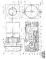
- Fig. 1 is a side view of the parking brake according to the invention.
- Fig. 2 is the orthogonal projection from left to right of FIG. 1.
- Fig. 3 is the section of FIG. 1 with the longitudinal plane A-A.
- Fig. 4 is the orthogonal projection of FIG. 1 from the narrow to the left.
- the invention comprises a pneumatic cylinder (1), single acting, in which a piston (2) moves, the rod of which plunges into a hydraulic cylinder (4), which is coaxial and screwed to the cylinder ( 1).
- the rod (3) ends and slides exactly in a circular duct (5), which is inserted axially into the piston (6) of the cylinder (4), a piston which has a longitudinal extension somewhat less than the length of the master bedroom (4).
- This conduit (5) terminates frontally in a circular chamber (5a), of a slightly larger diameter, from which radiate outwards and backwards small radio-axial conduits (7) through which the oil joins the subtle annular gap (8), which surrounds the rod (3) and which is interposed between the rear face of the piston (6) and the bottom wall (4a) of the cylinder (4).
- the piston (6) has on its outside, anterior face, a diametrical ridge (6a), wedge-shaped, which fits exactly and which slides in a conforming groove (9a) which longitudinally cuts a hollow shaft (9) ), which crosses diametrically the front bottom wall (4b) of the cylinder (4), suitably sized and shaped.
- the oil first, flows back through the radio-axial conduits (7) into the subtle annular chamber (8), located behind the piston (6), then, put under pressure by the pressing rod (3), it pushes forward the udder tone (6), whose front corner (6a) presses and fits into the longitudinal groove (9a) of the shaft (9), which, as we sketched in our introduction, results in solidarity to the mass of the press.
- the oil under pressure can be withdrawn through a special tapped hole (8b) provided on the wall of the cylinder (4), which is collated by a tube to the above-mentioned device intended to inter + capture the compressed air.
- the piston (6) when it advances, obstructs and pushes back two bars (11) which slide longitudinally in the bottom wall (4b) of the cylinder (4) and which press against a circular slide (12), the setback is opposed by an elastic member (13), the preload of which can be adjusted by acting on the nut (14) screwed onto the outer wall of the bottom (4b).
- These cylindrical bars (11) have the role of pushing back in its primitive position and of resting the piston (6) when the parking brake is disconnected, in such a way that the corner (6a) can be detached from the walls of the groove (9a) and therefore the free insertion of the shaft (9), dragged by the mass in its alternative strokes.
- the braking prismatic couple for example, instead of being constituted by a wedge sliding in a corresponding groove executed lengthwise on the shaft (9), as we have described above, could indifferently consist of one or more skates capable of surrounding and holding stationary, by adhesion, the shaft (9).
Landscapes
- Engineering & Computer Science (AREA)
- Mechanical Engineering (AREA)
- Braking Arrangements (AREA)
Applications Claiming Priority (2)
| Application Number | Priority Date | Filing Date | Title |
|---|---|---|---|
| IT00610/83A IT1172468B (it) | 1983-02-23 | 1983-02-23 | Freno di stazionamento per presse meccaniche od idrauliche |
| IT61083 | 1983-02-23 |
Publications (2)
| Publication Number | Publication Date |
|---|---|
| EP0117851A2 true EP0117851A2 (de) | 1984-09-05 |
| EP0117851A3 EP0117851A3 (de) | 1985-10-09 |
Family
ID=11292250
Family Applications (1)
| Application Number | Title | Priority Date | Filing Date |
|---|---|---|---|
| EP84830040A Withdrawn EP0117851A3 (de) | 1983-02-23 | 1984-02-16 | Stillstandbremse für mechanische oder hydraulische Pressen |
Country Status (2)
| Country | Link |
|---|---|
| EP (1) | EP0117851A3 (de) |
| IT (1) | IT1172468B (de) |
Cited By (2)
| Publication number | Priority date | Publication date | Assignee | Title |
|---|---|---|---|---|
| US5421920A (en) * | 1992-09-24 | 1995-06-06 | Nippon Steel Corporation | Process for producing rolled shape steel material having high strength, high toughness, and excellent fire resistance |
| CN114810879A (zh) * | 2022-06-08 | 2022-07-29 | 浙江师范大学 | 一种复合式线控制动器 |
Family Cites Families (5)
| Publication number | Priority date | Publication date | Assignee | Title |
|---|---|---|---|---|
| GB923516A (de) * | 1900-01-01 | |||
| BE431827A (de) * | 1937-12-23 | |||
| FR944111A (fr) * | 1947-03-28 | 1949-03-28 | A E R E M | Presse mécanique à découper, à emboutir ou autre application |
| FR1232693A (fr) * | 1958-08-26 | 1960-10-11 | Schuler L Ag | Dispositif pour fixer la partie de travail mobile, notamment de presses mécaniques, en empêchant leur mouvement de fermeture intempestif |
| FR2230495A1 (en) * | 1973-05-23 | 1974-12-20 | Jambon Anciens Ateliers H | Hydraulic screw press - fault actuates valve to maintain pressure and lock screws |
-
1983
- 1983-02-23 IT IT00610/83A patent/IT1172468B/it active
-
1984
- 1984-02-16 EP EP84830040A patent/EP0117851A3/de not_active Withdrawn
Cited By (3)
| Publication number | Priority date | Publication date | Assignee | Title |
|---|---|---|---|---|
| US5421920A (en) * | 1992-09-24 | 1995-06-06 | Nippon Steel Corporation | Process for producing rolled shape steel material having high strength, high toughness, and excellent fire resistance |
| US5985051A (en) * | 1992-09-24 | 1999-11-16 | Nippon Steel Corporation | Shape steel material having high strength, high toughness and excellent fire resistance and process for producing rolled shape steel of said material |
| CN114810879A (zh) * | 2022-06-08 | 2022-07-29 | 浙江师范大学 | 一种复合式线控制动器 |
Also Published As
| Publication number | Publication date |
|---|---|
| EP0117851A3 (de) | 1985-10-09 |
| IT1172468B (it) | 1987-06-18 |
| IT8300610A0 (it) | 1983-02-23 |
Similar Documents
| Publication | Publication Date | Title |
|---|---|---|
| FR2756797A1 (fr) | Dispositif de freinage hydraulique | |
| FR2467752A1 (fr) | Systeme de freinage hydraulique | |
| FR2656049A1 (fr) | Accumulateur de pression a piston, notamment pour systeme de freinage a regulation du glissement de traction. | |
| FR2559723A1 (fr) | Systeme hydraulique de freinage avec controle du glissement | |
| EP0117851A2 (de) | Stillstandbremse für mechanische oder hydraulische Pressen | |
| FR2549187A1 (fr) | Variateur de vitesse a courroie et disques coniques | |
| FR2652790A1 (fr) | Systeme hydraulique de freinage antiblocage pour vehicule automobile. | |
| FR2473143A1 (fr) | Ensemble constitue par l'adaptation d'un frein d'immobilisation au frein de service d'un bloc de freinage | |
| FR2509805A1 (fr) | Amplificateur de force hydraulique | |
| FR2464169A1 (fr) | Maitre-cylindre multiplicateur pour installations hydrauliques de freinage de vehicules | |
| FR2479929A1 (fr) | Mecanisme d'accouplement a disques, equipe de pistons asservis de dimensions differentes | |
| EP1463656A1 (de) | Elektrohydraulischer bremskreis für fahrzeug | |
| FR2611236A1 (fr) | Pompe hydraulique a pistons axiaux munie de clapets antiretour de refoulement commandes hydrauliquement | |
| EP0289396B1 (de) | Steuerventil, insbesondere für die hydraulischen Bremsen eines Fahrzeugs | |
| FR1465713A (fr) | Valve double de retenue pour circuits hydrauliques divers et notamment pour ceux assurant la direction de véhicules circulant sur terrains variés | |
| FR2561320A1 (fr) | Emetteur de pression hydraulique et son joint annulaire d'etancheite | |
| FR2586983A1 (fr) | Systeme de freinage a regulation du glissement | |
| FR2515592A1 (fr) | Installation de freinage pour remorques de vehicules automobiles | |
| FR2590957A1 (fr) | Agencement d'etancheite pour une unite piston-cylindre | |
| FR2589416A1 (fr) | Generateur de pression de freinage | |
| FR3002991A1 (fr) | Circuit hydraulique comprenant une commande de freinage statique temporisee | |
| CH138175A (fr) | Installation hydro-pneumatique applicable notamment à la commande des freins de véhicules. | |
| CH338704A (fr) | Mécanisme hydraulique pour la commande des pales d'une hélice à pas réglable | |
| EP0041020A1 (de) | Druckdosiereinheit für eine Bedienungseinrichtung für Fahrzeugbremsen | |
| FR2583694A1 (fr) | Systeme de freinage hydraulique |
Legal Events
| Date | Code | Title | Description |
|---|---|---|---|
| PUAI | Public reference made under article 153(3) epc to a published international application that has entered the european phase |
Free format text: ORIGINAL CODE: 0009012 |
|
| AK | Designated contracting states |
Designated state(s): AT BE CH DE FR GB LI LU NL SE |
|
| PUAL | Search report despatched |
Free format text: ORIGINAL CODE: 0009013 |
|
| AK | Designated contracting states |
Designated state(s): AT BE CH DE FR GB LI LU NL SE |
|
| 17P | Request for examination filed |
Effective date: 19860409 |
|
| 17Q | First examination report despatched |
Effective date: 19870720 |
|
| STAA | Information on the status of an ep patent application or granted ep patent |
Free format text: STATUS: THE APPLICATION IS DEEMED TO BE WITHDRAWN |
|
| 18D | Application deemed to be withdrawn |
Effective date: 19880604 |