EP0118155B1 - Dispositif de commande automatique du verrouillage d'un différentiel - Google Patents
Dispositif de commande automatique du verrouillage d'un différentiel Download PDFInfo
- Publication number
- EP0118155B1 EP0118155B1 EP84200265A EP84200265A EP0118155B1 EP 0118155 B1 EP0118155 B1 EP 0118155B1 EP 84200265 A EP84200265 A EP 84200265A EP 84200265 A EP84200265 A EP 84200265A EP 0118155 B1 EP0118155 B1 EP 0118155B1
- Authority
- EP
- European Patent Office
- Prior art keywords
- differential
- clutch
- wheels
- lock
- actuated
- Prior art date
- Legal status (The legal status is an assumption and is not a legal conclusion. Google has not performed a legal analysis and makes no representation as to the accuracy of the status listed.)
- Expired
Links
- 230000004913 activation Effects 0.000 claims description 5
- 238000005461 lubrication Methods 0.000 claims description 3
- 230000003213 activating effect Effects 0.000 claims 2
- 241000239290 Araneae Species 0.000 description 3
- 238000010586 diagram Methods 0.000 description 3
- 230000008901 benefit Effects 0.000 description 2
- 238000003780 insertion Methods 0.000 description 2
- 230000037431 insertion Effects 0.000 description 2
- 230000007420 reactivation Effects 0.000 description 2
- 230000009471 action Effects 0.000 description 1
- 230000005540 biological transmission Effects 0.000 description 1
- 238000009826 distribution Methods 0.000 description 1
- 238000009434 installation Methods 0.000 description 1
- 238000012423 maintenance Methods 0.000 description 1
- 238000004519 manufacturing process Methods 0.000 description 1
- 238000000034 method Methods 0.000 description 1
- 230000008569 process Effects 0.000 description 1
- 230000001141 propulsive effect Effects 0.000 description 1
Images

Classifications
-
- F—MECHANICAL ENGINEERING; LIGHTING; HEATING; WEAPONS; BLASTING
- F16—ENGINEERING ELEMENTS AND UNITS; GENERAL MEASURES FOR PRODUCING AND MAINTAINING EFFECTIVE FUNCTIONING OF MACHINES OR INSTALLATIONS; THERMAL INSULATION IN GENERAL
- F16H—GEARING
- F16H48/00—Differential gearings
- F16H48/20—Arrangements for suppressing or influencing the differential action, e.g. locking devices
- F16H48/22—Arrangements for suppressing or influencing the differential action, e.g. locking devices using friction clutches or brakes
-
- B—PERFORMING OPERATIONS; TRANSPORTING
- B60—VEHICLES IN GENERAL
- B60K—ARRANGEMENT OR MOUNTING OF PROPULSION UNITS OR OF TRANSMISSIONS IN VEHICLES; ARRANGEMENT OR MOUNTING OF PLURAL DIVERSE PRIME-MOVERS IN VEHICLES; AUXILIARY DRIVES FOR VEHICLES; INSTRUMENTATION OR DASHBOARDS FOR VEHICLES; ARRANGEMENTS IN CONNECTION WITH COOLING, AIR INTAKE, GAS EXHAUST OR FUEL SUPPLY OF PROPULSION UNITS IN VEHICLES
- B60K17/00—Arrangement or mounting of transmissions in vehicles
- B60K17/34—Arrangement or mounting of transmissions in vehicles for driving both front and rear wheels, e.g. four wheel drive vehicles
- B60K17/344—Arrangement or mounting of transmissions in vehicles for driving both front and rear wheels, e.g. four wheel drive vehicles having a transfer gear
- B60K17/346—Arrangement or mounting of transmissions in vehicles for driving both front and rear wheels, e.g. four wheel drive vehicles having a transfer gear the transfer gear being a differential gear
- B60K17/3462—Arrangement or mounting of transmissions in vehicles for driving both front and rear wheels, e.g. four wheel drive vehicles having a transfer gear the transfer gear being a differential gear with means for changing distribution of torque between front and rear wheels
-
- B—PERFORMING OPERATIONS; TRANSPORTING
- B60—VEHICLES IN GENERAL
- B60K—ARRANGEMENT OR MOUNTING OF PROPULSION UNITS OR OF TRANSMISSIONS IN VEHICLES; ARRANGEMENT OR MOUNTING OF PLURAL DIVERSE PRIME-MOVERS IN VEHICLES; AUXILIARY DRIVES FOR VEHICLES; INSTRUMENTATION OR DASHBOARDS FOR VEHICLES; ARRANGEMENTS IN CONNECTION WITH COOLING, AIR INTAKE, GAS EXHAUST OR FUEL SUPPLY OF PROPULSION UNITS IN VEHICLES
- B60K23/00—Arrangement or mounting of control devices for vehicle transmissions, or parts thereof, not otherwise provided for
- B60K23/08—Arrangement or mounting of control devices for vehicle transmissions, or parts thereof, not otherwise provided for for changing number of driven wheels, for switching from driving one axle to driving two or more axles
- B60K23/0808—Arrangement or mounting of control devices for vehicle transmissions, or parts thereof, not otherwise provided for for changing number of driven wheels, for switching from driving one axle to driving two or more axles for varying torque distribution between driven axles, e.g. by transfer clutch
-
- F—MECHANICAL ENGINEERING; LIGHTING; HEATING; WEAPONS; BLASTING
- F16—ENGINEERING ELEMENTS AND UNITS; GENERAL MEASURES FOR PRODUCING AND MAINTAINING EFFECTIVE FUNCTIONING OF MACHINES OR INSTALLATIONS; THERMAL INSULATION IN GENERAL
- F16H—GEARING
- F16H48/00—Differential gearings
- F16H48/06—Differential gearings with gears having orbital motion
- F16H48/08—Differential gearings with gears having orbital motion comprising bevel gears
-
- F—MECHANICAL ENGINEERING; LIGHTING; HEATING; WEAPONS; BLASTING
- F16—ENGINEERING ELEMENTS AND UNITS; GENERAL MEASURES FOR PRODUCING AND MAINTAINING EFFECTIVE FUNCTIONING OF MACHINES OR INSTALLATIONS; THERMAL INSULATION IN GENERAL
- F16H—GEARING
- F16H48/00—Differential gearings
- F16H48/20—Arrangements for suppressing or influencing the differential action, e.g. locking devices
- F16H48/30—Arrangements for suppressing or influencing the differential action, e.g. locking devices using externally-actuatable means
-
- F—MECHANICAL ENGINEERING; LIGHTING; HEATING; WEAPONS; BLASTING
- F16—ENGINEERING ELEMENTS AND UNITS; GENERAL MEASURES FOR PRODUCING AND MAINTAINING EFFECTIVE FUNCTIONING OF MACHINES OR INSTALLATIONS; THERMAL INSULATION IN GENERAL
- F16H—GEARING
- F16H48/00—Differential gearings
- F16H48/20—Arrangements for suppressing or influencing the differential action, e.g. locking devices
- F16H48/30—Arrangements for suppressing or influencing the differential action, e.g. locking devices using externally-actuatable means
- F16H48/34—Arrangements for suppressing or influencing the differential action, e.g. locking devices using externally-actuatable means using electromagnetic or electric actuators
-
- F—MECHANICAL ENGINEERING; LIGHTING; HEATING; WEAPONS; BLASTING
- F16—ENGINEERING ELEMENTS AND UNITS; GENERAL MEASURES FOR PRODUCING AND MAINTAINING EFFECTIVE FUNCTIONING OF MACHINES OR INSTALLATIONS; THERMAL INSULATION IN GENERAL
- F16H—GEARING
- F16H48/00—Differential gearings
- F16H48/06—Differential gearings with gears having orbital motion
- F16H48/08—Differential gearings with gears having orbital motion comprising bevel gears
- F16H2048/085—Differential gearings with gears having orbital motion comprising bevel gears characterised by shafts or gear carriers for orbital gears
-
- F—MECHANICAL ENGINEERING; LIGHTING; HEATING; WEAPONS; BLASTING
- F16—ENGINEERING ELEMENTS AND UNITS; GENERAL MEASURES FOR PRODUCING AND MAINTAINING EFFECTIVE FUNCTIONING OF MACHINES OR INSTALLATIONS; THERMAL INSULATION IN GENERAL
- F16H—GEARING
- F16H48/00—Differential gearings
- F16H48/20—Arrangements for suppressing or influencing the differential action, e.g. locking devices
- F16H2048/204—Control of arrangements for suppressing differential actions
-
- F—MECHANICAL ENGINEERING; LIGHTING; HEATING; WEAPONS; BLASTING
- F16—ENGINEERING ELEMENTS AND UNITS; GENERAL MEASURES FOR PRODUCING AND MAINTAINING EFFECTIVE FUNCTIONING OF MACHINES OR INSTALLATIONS; THERMAL INSULATION IN GENERAL
- F16H—GEARING
- F16H2200/00—Transmissions for multiple ratios
- F16H2200/20—Transmissions using gears with orbital motion
- F16H2200/203—Transmissions using gears with orbital motion characterised by the engaging friction means not of the freewheel type, e.g. friction clutches or brakes
- F16H2200/2071—Transmissions using gears with orbital motion characterised by the engaging friction means not of the freewheel type, e.g. friction clutches or brakes using three freewheel mechanism
-
- F—MECHANICAL ENGINEERING; LIGHTING; HEATING; WEAPONS; BLASTING
- F16—ENGINEERING ELEMENTS AND UNITS; GENERAL MEASURES FOR PRODUCING AND MAINTAINING EFFECTIVE FUNCTIONING OF MACHINES OR INSTALLATIONS; THERMAL INSULATION IN GENERAL
- F16H—GEARING
- F16H48/00—Differential gearings
- F16H48/20—Arrangements for suppressing or influencing the differential action, e.g. locking devices
- F16H48/30—Arrangements for suppressing or influencing the differential action, e.g. locking devices using externally-actuatable means
- F16H48/32—Arrangements for suppressing or influencing the differential action, e.g. locking devices using externally-actuatable means using fluid pressure actuators
Definitions
- the invention relates to an automatic control device for controlling the lock of a differential.
- a device with manual insertion at will of the driver comprising a slidable grooved sleeve which rigidly connects to one another the two axel shafts of the driving wheels so as to render inoperative the differential (Zahnradgetriebe, J. Looman, 1970; p. 235, 236); alternatively, the sleeve, when sliding, may lock the planetary gears on their own axes or one of the crown wheels to the spider box thereby still obtaining the same result, i.e. the disactivation of the differential.
- a selflocking differential is used provided with a series of pins or radially sliding rollers, inserted into the driving member of the differential, or clutch discs are inserted between the elements rigidly connected to the crown wheels and the spider.
- the pins move radially by following the undulations of the profiles of the driven elements thereby transmitting different torques.
- a certain difference in the speed of the two axel shafts is exceeded, a periodical intervention of the clutches is produced with an intensity which is as greater as higher is the rotation speed of the pivots of the planetary gears.
- the selflocking differentials of this type have the disadvantage consisting in that they imply pre-established locking values and operate even in conditions in which their intervention is not required.
- Another device is the differential with viscous clutch lock which takes advantage of the action of viscous forces proportional to the speed variation between the input and the output of the differential; in this case the transmitted torque is affected by the temperature of the viscous element, and moreover it is impossible to adjust the locking degree, and since there is no operation threshold the lock intervenes always, even in cases in which such intervention is not necessary, as for example in case of very sharp curves.
- the object of the invention is to provide an automatic control device for controlling the lock of a differential having the particular advantage of to become operating in an automatical manner only when certain conditions arise, i.e. for certain speed difference values between the input and the output of the differential.
- the device proposed allows transferring the torque onto the wheel in conditions of adhesion, thus ensuring the necessary propulsive thrust for the vehicle.
- the device proposed is simple to manufacture and can be mounted on vehicles which utilize the transmission on two or all four wheels, and in this second case, with a central differential.
- the proposed device does not give rise to serious problems as regards either the installation or the maintenance, unlike the analogous devices utilized at present time.
- the invention proposes to provide an automatic control device for controlling the lock of a differential as defined in claim 1 and 2 respectively.
- the features as defined in the respective preamble are known from US-A-3845671.
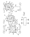
- Figure 1 is a diagrammatic representation of a conventional differential 10 in which a spider box 11 receives the motion from a driving shaft 12 of a motor 13 through a gearbox 14 and a gear 15 as an input member.
- the box 11 encloses planet wheels 16 meshing with crown wheels 17 keyed on axle shafts 18 of wheels 19.
- a sensor V for sensing the speed of the input member 15 of the differential is mounted in register with the gear 15, and a sensor V 2 sensing the speed of the driving element of the differential is mounted in register with an axle shaft 18.
- the data detected by the sensors V, and V 2 are supplied to a microprocessor (comparator means) 20 which in its turn controls an electrovalve E whose function consists in actuating an operating cylinder 21 ( Figure 3) of a differential lock clutch 22 ( Figures 1 and 3).
- the hydraulic circuit ( Figure 3) comprises a conventional lubrication oil carter 24 of the motor 13, provided with a pump 23, and into which there is inserted the electrovalve E which, as said before, controls the operating cylinder 21 of the clutch 22 inserted between the crown wheels 17 of the differential.
- the operation of the device is as follows: when the difference between the speed of the input element and the speed of the driven element is higher than or equal to a predetermined value A, the said activation threshold, i.e. in formula
- V 1 -V 2 is in absolute value, so that a single sensor V 2 may be mounted on an axle shaft 18 instead of a sensor for each axle shaft; thus, a value V 1 -V 2 is obtained independently from whether the right-hand wheel or the left-hand wheel is slipping.
- e is defined as threshold between the opening and the closure of the clutch (delay)
- the system is prepared for taking off current from the electrovalve E and therefore, the clutch 22 is disconnected and thus activates again the differential.
- the device automatically becomes operating when certain conditions arise, i.e. for certain values of ⁇ V between the input and the output of the differential; it will be up to the manufacturer and the designer to dimension the microprocessor and to calculate the values of A (activation threshold) and e (delay threshold) in order that the device becomes operating only under determined operation conditions of the vehicle, namely of the kind of the slipping of a wheel, but only when the conditions are such as to require the lock of the differential.
- FIG. 1 The more general technical solution shown in Figures 1, and 3 may be applied, for example, to a vehicle with four driving wheels with a central differential.
- This technical solution is diagrammatically shown in Figure 4 in which three differentials 10,, 10 c , 10p, i.e. front, central and back differentials, respectively, can be seen.
- the common reference numbers of these three differentials and that of the technical solution of Figure 1 have as the only difference the letter a, c and p which indicates frontal, central and back.
- sensor V 1 is applied to input member of the central differential 10 c
- sensor V 2 is applied to driven element 18 c of the central differential connected to back axle 18 p .
- the microprocessor 20 verifies the inequality V 1 ⁇ V 2 ; in fact, two cases may take place, namely V 2 >V 1 and therefore a slipping of the back carriage, or V 1 >V 2 and therefore a slipping of the forecarriage.
- the microprocessor 20 operates according to the logic
- ⁇ B being the delay threshold, i.e. there is an acceptable slipping of the back carriage, the current is taken off from the electrovalves E 1 and E 2 with the consequent opening of the clutches 22 r and 22 P and reactivation of the central differential 10 c and the back differential 10 p .
- the microprocessor 20 operates m accordance with the logic
- ⁇ A being the delay threshold
- current is taken off from the electrovalve E 1 with consequent opening of the clutch 22 c and reactivation of the central differential 10 c .
- the microprocessor 20 verifies the inequalities V 1 ⁇ V 2 and in accordance with the two cases:
- the electrovalve E is single, so that, depending on the existing conditions described hereinabove and namely
- the intervention condition has been terminated, i.e. in the situation respectively current will be disinserted from the electrovalve E with consequent opening of the clutches 22 c and 22p.
Landscapes
- Engineering & Computer Science (AREA)
- General Engineering & Computer Science (AREA)
- Mechanical Engineering (AREA)
- Chemical & Material Sciences (AREA)
- Combustion & Propulsion (AREA)
- Transportation (AREA)
- Physics & Mathematics (AREA)
- Electromagnetism (AREA)
- Retarders (AREA)
Claims (2)
Applications Claiming Priority (2)
| Application Number | Priority Date | Filing Date | Title |
|---|---|---|---|
| IT67241/83A IT1158817B (it) | 1983-03-03 | 1983-03-03 | Dispositivo di comando automatico del bloccaggio di un differenziale |
| IT6724183 | 1983-03-03 |
Publications (2)
| Publication Number | Publication Date |
|---|---|
| EP0118155A1 EP0118155A1 (fr) | 1984-09-12 |
| EP0118155B1 true EP0118155B1 (fr) | 1988-10-19 |
Family
ID=11300768
Family Applications (1)
| Application Number | Title | Priority Date | Filing Date |
|---|---|---|---|
| EP84200265A Expired EP0118155B1 (fr) | 1983-03-03 | 1984-02-24 | Dispositif de commande automatique du verrouillage d'un différentiel |
Country Status (3)
| Country | Link |
|---|---|
| EP (1) | EP0118155B1 (fr) |
| DE (1) | DE3474711D1 (fr) |
| IT (1) | IT1158817B (fr) |
Families Citing this family (8)
| Publication number | Priority date | Publication date | Assignee | Title |
|---|---|---|---|---|
| DE3338940A1 (de) * | 1983-10-27 | 1985-05-09 | Klöckner-Humboldt-Deutz AG, 5000 Köln | Ackerschlepper mit zwei antreibbaren, differentialgetriebe aufweisenden achsen |
| DE3507490C1 (de) * | 1985-03-02 | 1986-03-13 | Dr.Ing.H.C. F. Porsche Ag, 7000 Stuttgart | Sperrsystem fuer ein Kraftfahrzeug mit Allradantrieb |
| US4702341A (en) * | 1985-12-13 | 1987-10-27 | Toyota Jidosha Kabushiki Kaisha | Four wheel drive vehicle slippage control device and method limiting center differential action according to input torque supplied thereto |
| AT386661B (de) * | 1986-02-11 | 1988-09-26 | Steyr Daimler Puch Ag | Sperrvorrichtung fuer ein ausgleichgetriebe zwischen den beiden antriebsraedern eines kraftfahrzeuges |
| US4840247A (en) * | 1986-05-06 | 1989-06-20 | Toyota Jidosha Kabushiki Kaisha | Device for controlling 4wd vehicle central differential restriction device according to front and rear wheels rotational speed difference, and method of operation thereof |
| IT1189667B (it) * | 1986-05-16 | 1988-02-04 | Fiat Auto Spa | Perfezionamenti ai sistemi di trasmissione per autoveicoli a quattro ruote motrici |
| EP0247820B1 (fr) * | 1986-05-26 | 1992-08-05 | Toyota Jidosha Kabushiki Kaisha | Transmission différentielle |
| DE3780871T2 (de) * | 1986-05-26 | 1995-08-31 | Toyota Motor Co Ltd | Differentialgetriebe. |
Citations (1)
| Publication number | Priority date | Publication date | Assignee | Title |
|---|---|---|---|---|
| WO1982001354A1 (fr) * | 1980-10-15 | 1982-04-29 | Ferguson Services Nv Massey | Commande electronique de vehicules agricoles |
Family Cites Families (4)
| Publication number | Priority date | Publication date | Assignee | Title |
|---|---|---|---|---|
| US2922482A (en) * | 1954-08-20 | 1960-01-26 | Fisher Andrew | Four wheel driven and steered tractor |
| DE2164324C2 (de) * | 1971-12-23 | 1984-08-16 | Daimler-Benz Ag, 7000 Stuttgart | Steuervorrichtung für ein sperrbares Ausgleichsgetriebe für Fahrzeuge |
| US3845671A (en) * | 1973-02-12 | 1974-11-05 | Chrysler Corp | Full time slip controlled four wheel drive |
| IT1039775B (it) * | 1974-07-30 | 1979-12-10 | Eaton Corp | Complesso a semiassi multipli do tato di un sistema automatico di blocco |
-
1983
- 1983-03-03 IT IT67241/83A patent/IT1158817B/it active
-
1984
- 1984-02-24 EP EP84200265A patent/EP0118155B1/fr not_active Expired
- 1984-02-24 DE DE8484200265T patent/DE3474711D1/de not_active Expired
Patent Citations (1)
| Publication number | Priority date | Publication date | Assignee | Title |
|---|---|---|---|---|
| WO1982001354A1 (fr) * | 1980-10-15 | 1982-04-29 | Ferguson Services Nv Massey | Commande electronique de vehicules agricoles |
Non-Patent Citations (1)
| Title |
|---|
| Zahnradgetriebe, J. Looman, 234-237, Springer-Verlag 1970 * |
Also Published As
| Publication number | Publication date |
|---|---|
| EP0118155A1 (fr) | 1984-09-12 |
| IT1158817B (it) | 1987-02-25 |
| DE3474711D1 (en) | 1988-11-24 |
| IT8367241A0 (it) | 1983-03-03 |
Similar Documents
| Publication | Publication Date | Title |
|---|---|---|
| EP0076148B1 (fr) | Système de commande pour le couple de transmission d'un véhicule à quatre roues motrices | |
| US4558414A (en) | System for controlling a power transmission of a four-wheel drive vehicle | |
| US4938306A (en) | Four-wheel-drive vehicle having a torque transmission coupling for always transmitting the torque | |
| US4298085A (en) | Automatic four-wheel drive transfer case | |
| EP0217087B1 (fr) | Système de commande de freinage pour véhicule à quatre roues motrices | |
| US5125490A (en) | Center differential lock mechanism controlling device | |
| EP0396323B1 (fr) | Système de contrôle de distribution du couple pour un véhicule à quatre roues motrices | |
| US6123183A (en) | Rotation transmission device | |
| EP1518741A2 (fr) | Unité de différentiel verrouillable à force magnétique | |
| US5016724A (en) | Inter-axle differential having a friction-type biasing clutch and wheel slip sensing control means therefor | |
| US5247443A (en) | Electronic control for vehicle four wheel drive system | |
| EP0118155B1 (fr) | Dispositif de commande automatique du verrouillage d'un différentiel | |
| US4773517A (en) | Torque control system for vehicles | |
| CN105465351A (zh) | 锁止式差速器控制 | |
| EP0421594B1 (fr) | Commande de répartition du couple pour véhicule à moteur à quatre roues motrices | |
| EP0415554B1 (fr) | Commande de répartition du couple pour véhicule automobile à quatre roues motrices | |
| EP0282187B1 (fr) | Transmission de puissance pour véhicule à quatre roues motrices | |
| US6644428B2 (en) | Automatic axle traction control | |
| JPH0424253B2 (fr) | ||
| US5809443A (en) | Four-wheel drive transfer case controller with compensation for tires with different diameters | |
| US7291094B2 (en) | Driving system for off-road utility vehicle | |
| US5954778A (en) | Four-wheel drive transfer case controller with torque decrement strategy | |
| JPS63203430A (ja) | ハイブリツド駆動車の駆動力制御装置 | |
| US4842111A (en) | Drive system for motor vehicles having driven front and rear axles | |
| JPS61157439A (ja) | 4輪駆動車の駆動力配分制御装置 |
Legal Events
| Date | Code | Title | Description |
|---|---|---|---|
| PUAI | Public reference made under article 153(3) epc to a published international application that has entered the european phase |
Free format text: ORIGINAL CODE: 0009012 |
|
| AK | Designated contracting states |
Designated state(s): DE FR GB IT SE |
|
| 17P | Request for examination filed |
Effective date: 19850219 |
|
| 17Q | First examination report despatched |
Effective date: 19860707 |
|
| R17C | First examination report despatched (corrected) |
Effective date: 19870205 |
|
| RAP1 | Party data changed (applicant data changed or rights of an application transferred) |
Owner name: ITALDESIGN S.P.A. |
|
| ITF | It: translation for a ep patent filed | ||
| GRAA | (expected) grant |
Free format text: ORIGINAL CODE: 0009210 |
|
| AK | Designated contracting states |
Kind code of ref document: B1 Designated state(s): DE FR GB IT SE |
|
| PG25 | Lapsed in a contracting state [announced via postgrant information from national office to epo] |
Ref country code: SE Effective date: 19881019 |
|
| REF | Corresponds to: |
Ref document number: 3474711 Country of ref document: DE Date of ref document: 19881124 |
|
| ET | Fr: translation filed | ||
| PLBE | No opposition filed within time limit |
Free format text: ORIGINAL CODE: 0009261 |
|
| STAA | Information on the status of an ep patent application or granted ep patent |
Free format text: STATUS: NO OPPOSITION FILED WITHIN TIME LIMIT |
|
| 26N | No opposition filed | ||
| PGFP | Annual fee paid to national office [announced via postgrant information from national office to epo] |
Ref country code: DE Payment date: 19920122 Year of fee payment: 9 |
|
| PGFP | Annual fee paid to national office [announced via postgrant information from national office to epo] |
Ref country code: FR Payment date: 19920225 Year of fee payment: 9 |
|
| ITTA | It: last paid annual fee | ||
| PGFP | Annual fee paid to national office [announced via postgrant information from national office to epo] |
Ref country code: GB Payment date: 19920608 Year of fee payment: 9 |
|
| PG25 | Lapsed in a contracting state [announced via postgrant information from national office to epo] |
Ref country code: GB Effective date: 19930224 |
|
| GBPC | Gb: european patent ceased through non-payment of renewal fee |
Effective date: 19930224 |
|
| PG25 | Lapsed in a contracting state [announced via postgrant information from national office to epo] |
Ref country code: FR Effective date: 19931029 |
|
| PG25 | Lapsed in a contracting state [announced via postgrant information from national office to epo] |
Ref country code: DE Effective date: 19931103 |
|
| REG | Reference to a national code |
Ref country code: FR Ref legal event code: ST |