EP0421594B1 - Commande de répartition du couple pour véhicule à moteur à quatre roues motrices - Google Patents
Commande de répartition du couple pour véhicule à moteur à quatre roues motrices Download PDFInfo
- Publication number
- EP0421594B1 EP0421594B1 EP90309218A EP90309218A EP0421594B1 EP 0421594 B1 EP0421594 B1 EP 0421594B1 EP 90309218 A EP90309218 A EP 90309218A EP 90309218 A EP90309218 A EP 90309218A EP 0421594 B1 EP0421594 B1 EP 0421594B1
- Authority
- EP
- European Patent Office
- Prior art keywords
- torque
- wheels
- slip ratio
- rear wheels
- vehicle
- Prior art date
- Legal status (The legal status is an assumption and is not a legal conclusion. Google has not performed a legal analysis and makes no representation as to the accuracy of the status listed.)
- Expired - Lifetime
Links
- 230000001133 acceleration Effects 0.000 claims description 18
- 230000005540 biological transmission Effects 0.000 claims description 13
- 230000001965 increasing effect Effects 0.000 claims description 4
- 238000012937 correction Methods 0.000 claims description 2
- 230000003068 static effect Effects 0.000 description 3
- 238000010586 diagram Methods 0.000 description 2
- 239000012530 fluid Substances 0.000 description 2
- 230000006866 deterioration Effects 0.000 description 1
- 230000002708 enhancing effect Effects 0.000 description 1
- 230000007257 malfunction Effects 0.000 description 1
- 238000000034 method Methods 0.000 description 1
Images


Classifications
-
- B—PERFORMING OPERATIONS; TRANSPORTING
- B60—VEHICLES IN GENERAL
- B60K—ARRANGEMENT OR MOUNTING OF PROPULSION UNITS OR OF TRANSMISSIONS IN VEHICLES; ARRANGEMENT OR MOUNTING OF PLURAL DIVERSE PRIME-MOVERS IN VEHICLES; AUXILIARY DRIVES FOR VEHICLES; INSTRUMENTATION OR DASHBOARDS FOR VEHICLES; ARRANGEMENTS IN CONNECTION WITH COOLING, AIR INTAKE, GAS EXHAUST OR FUEL SUPPLY OF PROPULSION UNITS IN VEHICLES
- B60K23/00—Arrangement or mounting of control devices for vehicle transmissions, or parts thereof, not otherwise provided for
- B60K23/08—Arrangement or mounting of control devices for vehicle transmissions, or parts thereof, not otherwise provided for for changing number of driven wheels, for switching from driving one axle to driving two or more axles
- B60K23/0808—Arrangement or mounting of control devices for vehicle transmissions, or parts thereof, not otherwise provided for for changing number of driven wheels, for switching from driving one axle to driving two or more axles for varying torque distribution between driven axles, e.g. by transfer clutch
Definitions
- the present invention relates to a torque distribution control system for a four-wheel drive motor vehicle having a central differential, and more particularly to a control system in which the output torque of a transmission is unequally distributed to front wheels and rear wheels in accordance with driving conditions.
- a fluid operated multiple-disk friction clutch is provided for restricting the differential operation.
- the torque distributed to the front wheels and the rear wheels is controlled by the torque of the friction clutch, thereby improving straight-ahead stability, acceleration and driveability.
- the central differential is arranged to unequally distribute the torque to the front wheels and the rear wheels.
- There are two methods of controlling such a distribution system one of which uses a front-weighted distribution while the other uses a rear-weighted distribution. In the front-wheel weighted system, a large torque is transmitted to the front wheels.
- the vehicle has good straight-ahead stability, it is inferior in the steering because it tends to drift off course.
- the larger torque is transmitted to the rear wheels.
- the vehicle has good steering and driveability on a dry road.
- the vehicle is liable to spin on a slippery road.
- a general disadvantage of the four-wheel drive vehicle is that all of the four wheels may slip (slipping spin) at the same time, causing difficulty in driving.
- the torque transmitted to the rear wheels is usually set to a larger value than that to the front wheels, so that the rear wheels may slip first.
- the vehicle can then be safely driven by the front wheels at small torque while the rear wheels idle.
- each wheel can sustain a larger side force.
- the driving force acceleration force
- each wheel can sustain a larger side force.
- the driving force and the side force change with the slip ratio of the wheel to the ground (slip ratio is described hereinafter in detail).
- the slip ratio changes in accordance with the condition of the road surface and the friction coefficient of the tyre.
- a predetermined value 10 to 20%
- the driving force and the sustainable side force are dramatically reduced, which results in deterioration of driving stability.
- the slip ratio of the rear-wheel is controlled so as not to exceed the predetermined value. If the system operates to increase the torque distributed to the front wheels in accordance with the reduction of the sustainable side force, slipping of the rear wheels is prevented to ensure the driving force. Therefore, it is desirable to control the torque distribution based on the rear-wheel slip ratio.
- Japanese Laid Open Patent Applications Nos. 62-55228, 62-261539 and 63-8026 disclose four-wheel drive control systems in which a central differential comprising a simple planetary gear device is provided.
- the standard torque to the front and rear wheels is unequally distributed at a ratio determined by a difference between pitch circles of gears of the planetary gear device.
- the torque-capacity of the clutch is controlled in accordance with the difference between the speeds of the front wheels and the rear wheels, or with a predetermined value corrected by vehicle speed and steering angle.
- the torque distribution is controlled by restricting the differential operation of the central differential. Therefore, the slip condition of the wheels on the road surface cannot be detected so that it is impossible to actively control the torque distribution in accordance with the slip conditions.
- the torque distribution cannot be controlled.
- the present invention seeks to provide a torque distribution control system for a four-wheel drive motor vehicle in which a large torque is distributed to rear wheels, thereby enabling control of a wide torque distribution range.
- the present invention also seeks to provide a system which may ensure good driveability, driving stability and steering in accordance with slip conditions.
- a system for controlling torque distribution to the front and rear wheels of a motor vehicle as defined in claim 1.
- the slip ratio of the rear wheels is calculated based on velocity of the rear wheels and the ground speed of the vehicle.
- the slip ratio is calculated based on the angular velocity of the front wheels before the slipping and acceleration of the vehicle.
- FIG. 1 shows a power transmission system for a four-wheel drive motor vehicle having a central differential according to the present invention.
- An engine 1 is mounted on a front portion of the vehicle.
- a clutch 2 and an automatic transmission 3 are disposed at the rear of the engine 1 in the longitudinal direction of the vehicle.
- An output of the automatic transmission 3 is transmitted to an output shaft 4 which is aligned with a central differential 20 for rearwardly transmitting the torque.
- the output shaft 4 is connected to a front drive shaft 5 which is arranged parallel to and beneath the automatic transmission 3 through a pair of reduction gears 25 and 26 of the central differential 20.
- the front drive shaft 5 is connected to front wheels 9 through a front differential 7 and axles 8.
- the output shaft 4 is connected to a rear drive shaft 6 through the central differential 20.
- the rear drive shaft 6 is connected to rear wheels 13 through a propeller shaft 10, a rear differential 11 and axles 12.
- the central differential 20 is a complex planetary gear device and comprises a first sun gear 21 integrally formed on the output shaft 4, a second sun gear 22 integrally formed on the rear drive shaft 6, and a combined planet pinion 23 comprising a first planet pinion 23a meshed with the first sun gear 21, and a second planet pinion 23b meshed with the second sun gear 22, and supported on a carrier 24.
- the carrier 24 is connected to the reduction drive gear 25.
- the output torque from the output shaft 4 of the transmission 3 is transmitted to the carrier 24 and the second sun gear 22 through the first sun gear 21 and pinions 23a, 23b at predetermined respective torque distribution ratios.
- the difference between the rotational speeds of the carrier 24 and the second sun gear 22 is absorbed by the rotation and revolution of the first and second planet pinions 23a and 23b.
- the first sun gear 21 is engaged with the first planet pinion 23a and the second sun gear 22 is engaged with the second planet pinion 23b.
- a standard torque distribution for a front torque T F and a rear torque T R can be set to various values by changing radii of pitch circles of the sun gears 21 and 22 and the pinions 23a and 23b.
- a fluid operated multiple-disk friction clutch 27 is provided adjacent the central differential 20 for restricting differential operation of the central differential 20.
- the clutch 27 comprises a drive drum 27a secured to the carrier 24, and a driven drum 27b secured to the rear drive shaft 6.
- a differential operation restricting clutch torque Tc is produced in the clutch 27, a part of the output torque of the second sun gear 22 is transmitted to the front wheels 9, thereby changing the distribution of the torque.
- the carrier 24 is coupled with the second sun gear 22 when the clutch 27 is entirely engaged, thereby locking the central differential 20.
- static weight distribution of a front static weight WF and a rear static weight WR are determined for example as WF : WR ⁇ 62 : 38 when the clutch is directly engaged, the distribution ratio of front torque and rear torque is 62 : 38 which is approximate to the weight distribution.
- the torque distribution is controlled in the range between the standard torque distribution weighted to the rear wheels 13 and the torque distribution on complete engagement of the clutch in accordance with the differential operation restricting clutch torque Tc.
- the hydraulic circuit of the control system for the clutch 27 comprises an oil pump 30, a pressure regulator valve 31, a pilot valve 35, a clutch control valve 33 and a solenoid operated duty control valve 38.
- the regulator valve 31 operates to regulate the pressure of oil supplied from the oil pump 30 driven by the engine to produce a line pressure and the line pressure is applied to a line pressure conduit 32.
- the conduit 32 is communicated with a passage 37 through the pilot valve 35.
- the passage 37 is communicated with the solenoid operated duty control valve 38 downstream of the orifice 36, and with one end of the clutch control valve 33 through a passage 39.
- the conduit 32 is communicated with the clutch control valve 33 through a passage 32a.
- the clutch control valve 33 is communicated with the clutch 27 through a passage 34.
- the solenoid operated valve 38 is operated by pulses from a control unit 50 at a duty ratio determined therein, thereby controlling the drain of the oil to provide a control pressure.
- the control pressure is applied to the clutch control valve 33 to control the oil supplied to the clutch 27 so as to control the clutch pressure (torque) and hence the differential operation restricting clutch torque Tc.
- the torque distribution is controlled in accordance with a feedback signal on the slip ratio of the rear wheels because the torque to the rear wheels is set to a value larger than that to the front wheels by arranging the central differential 20 so that the rear wheels-slip first.
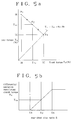
- Fig. 2a shows relationships between the driving force T or the sustainable side force F corresponding to the slip ratio S.
- the slip ratio is zero, the sustainable side force F is maximum and gradually reduces as the slip ratio S increases.
- the driving force T increases with the slip ratio S and reduces when the slip ratio exceeds a predetermined slip ratio Sa (10 to 20%).
- the range smaller than the slip ratio Sb (for example 3%) is determined as a dead zone where apparent slip ratio produced in accordance with the difference between the speed of the front wheels 9 and the speed of rear wheels 13 at a maximum steering angle is included.
- the control range becomes Sb ⁇ S ⁇ Sa.
- the slip ratio S is calculated within the control range to control the differential operation restricting clutch torque To as an increasing function of the slip ratio, so that a part of the torque to the rear wheels 13 is transmitted to the front wheels 9. Consequently, the sustainable side force F of the rear wheels 13 can be increased.
- the control unit 50 is supplied with output signals from a front-wheel speed sensor 40 and a rear-wheel speed sensor 41.
- the control unit 50 has a slip ratio calculator 51 to which a front-wheel angular velocity ⁇ F and a rear-wheel angular velocity ⁇ R from the sensors 40 and 41 are applied.
- a slip ratio S is calculated in accordance with the above mentioned equations.
- the slip ratio S is applied to a differential operation restricting clutch torque setting section 52.
- the clutch torque setting section 52 retrieves the clutch torque Tc from a look up table.
- Fig. 2b shows the clutch torque Tc stored in the look up table.
- the clutch torque Tc is an increasing function of the slip ratio S in the control range Sb ⁇ S ⁇ Sa.
- the clutch torque Tc is applied to a control quantity providing section 53 in which duty ratio D corresponding to the derived clutch torque Tc is provided.
- a duty ratio D provided at the section 53 is applied to the solenoid operated duty control valve 38 through a driver 54.
- the power of the engine 1 is transmitted to the transmission 3 through the clutch 2 at which the transmission ratio is automatically controlled.
- the output of the transmission is transmitted to the first sun gear 21 of the central differential 20.
- the front torque T F and the rear torque T R are determined in accordance with the radii of gears of the central differential 20.
- the torque is transmitted to the reduction gear 25 through the carrier 24 at a ratio of 34% for example and to the second sun gear 22 at the ratio of 66%.
- the front-wheel angular velocity ⁇ F and the rear-wheel angular velocity ⁇ R are detected by the front-wheel speed sensor 40 and the rear-wheel speed sensor 41.
- the rear-wheel slip ratio S becomes a smaller value than the actual slip ratio because the front-wheel angular velocity ⁇ F becomes higher than the ground speed V.
- the control unit 50 is provided with an acceleration sensor 43.
- a vehicle body acceleration a detected by the acceleration sensor 43 is applied to a front-wheel slipping determining section 57.
- the rear-wheel angular velocity ⁇ R detected by the sensor 41 is applied to the rear-wheel slip ratio calculator 51.
- the front-wheel angular velocity ⁇ F is applied to a changing rate calculator 58 where a changing rate d ⁇ F/dt of the front-wheel angular velocity ⁇ F is calculated.
- the changing rate d ⁇ F/.dt is applied to the front-wheel slipping determining section 57 in which the changing rate d ⁇ F/dt is compared with the vehicle body acceleration ⁇ . If d ⁇ F/dt > ⁇ , slipping of the front wheels 9 is determined.
- the result of the comparison and the acceleration a are applied to a front-wheel angular velocity correcting section 59 to which the front-wheel angular velocity ⁇ F is also applied.
- an actual front-wheel angular velocity Fa is calculated as follows, using a front-wheel angular velocity ⁇ F' before slipping, the detected acceleration ⁇ , and a calculating time ⁇ t.
- ⁇ Fa ⁇ F' + ⁇ ⁇ ⁇ t
- the front-wheel angular velocity ⁇ F is applied to the rear-wheel slip ratio calculator 51 through the section 59.
- the torque of the reduction drive gear 25 is transmitted to the front wheels 9 through the reduction driven gear 26, the front drive shaft 5 and the front differential 7 at the ratio of 34%.
- the torque at distribution ratio of 66% is transmitted to the rear wheels 13 through the second sun gear 22, the rear drive shaft 6, the propeller shaft 10 and the rear differential 11.
- the rear wheels 13 slip first because the larger amount of the torque is distributed to the rear wheels 13. If the calculated rear-wheel slip ratio becomes a value S2 in the control range, the driving of the rear wheels 13 is unstable. Therefore, a differential operation restricting clutch torque T2 is determined corresponding to the slip ratio S2. Consequently, the clutch torque Tc2 is produced in the clutch 27.
- the clutch 27 is provided in parallel with the carrier 24 and the second sun gear 22 of the central differential 20. Accordingly, the torque is transmitted from the second sun gear 22 to the carrier 24 to increase the torque to the front wheels 9.
- the distribution ratio of the front torque and the rear torque T F :T R becomes T F2 :T R2 at a point P2 of Fig. 5a.
- torque to the rear wheels 13 is reduced to eliminate slipping, thereby improving driveability to ensure good operability and safe driving.
- the rear-wheel slip ratio is calculated to determine the differential operation restricting clutch torque for controlling the torque distribution. Since a necessary minimum torque is transmitted to the front wheels for preventing slipping, thereby enhancing stability and steerability of the vehicle.
- control range in accordance with the slip ratio is properly determined by the characteristics of the driving power and the sustainable side force.
- the tight corner braking is effetively prevented to ensure the driveability.
- the rear-wheel slip ratio is calculated in accordance with the front-wheel speed as the vehicle speed, so that the calculation is simplified and corrections of various factors can be easily achieved.
Landscapes
- Engineering & Computer Science (AREA)
- Chemical & Material Sciences (AREA)
- Combustion & Propulsion (AREA)
- Transportation (AREA)
- Mechanical Engineering (AREA)
- Arrangement And Driving Of Transmission Devices (AREA)
Claims (6)
- Système de contrôle de distribution du couple de transmission aux roues avant et aux roues arrière (9, 13) d'un véhicule à moteur ayant une transmission 53), un capteur de vitesse de roues arrière (41), un capteur de vitesse de roues avant (40), une unité de commande (50) y compris un calculateur de glissement de roues arrière (51) pour calculer le rapport de glissement (S) des roues arrière du véhicule (13) en fonction des vitesses des roues avant et des roues arrière,
un engrenage central différentiel (20) pour répartir un couple de sortie de transmission 53) entre les roues avant et les roues arrière (9, 13) et un dispositif réducteur variable pour réduire le mouvement différentiel de l'engrenage différentiel central en fonction de l'augmentation du rapport de glissement (S) des roues arrière, caractérisé par le fait que l'engrenage central différentiel (20) est configuré pour répartir un couple plus fort aux roues arrières (13) qu'aux roues avant (9) en fonctionnement sans réduction; et par le fait que ce système comprend en outre
un capteur d'accélération (43) pour détecter l'accélération effective du véhicule,
un calculateur de pourcentage de changement de vitesse (58) pour calculer l'accélération à partir du pourcentage de changement de vitesse des roues avant capté par le capteur de vitesse des roues avant (40),
une section de détermination de glissement des roues avant (57) répondant à l'accélération effective et à l'accélération calculée pour déterminer le glissement des roues avant, et
une section de correction de vitesse angulaire de roues avant (59) répondant à la vitesse des roues avant et au glissement des roues avant pour appliquer une correction au calculateur de rapport de glissement des roues arrière (51) pour que le calcul du rapport de glissement des roues arrière (S). - Système selon la revendication 1, dans lequel le dispositif réducteur est un embrayage hydraulique (27) raccordé en parallèle à l'engrenage différentiel (20), de façon à ce que l'action du différentiel se réduise au fur et à mesure que la prise de l'embrayage (27) augmente.
- Système selon la revendication 1 ou la revendication 2, dans lequel le rapport de glissement (S) des roues arrières (13) est calculé d'après la vitesse des roues arrières et d'après la vitesse au sol calculée du véhicule.
- Système selon l'une quelconque des revendications précédentes, dans lequel lorsque les roues avant glissent le rapport de glissement des roues arrière (S) est calculé d'après la vitesse angulaire des roues avant que le glissement ne se produise et d'après l'accélération du véhicule.
- Système selon la revendication 3, dans lequel la vitesse au sol du véhicule est calculée d'après la vitesse angulaire des roues avant.
- Système selon l'une quelconque des revendications précédentes, dans lequel l'engrenage différentiel central (90) comprend
un dispositif à engrenages planétaires comprenant un premier pignon soleil (21) raccordé à l'arbre de sortie (4) de la transmission (3), un entraîneur (24) un premier et un second engrenage planétaire (23) faisant un seul et même ensemble supportés par l'entraîneur 24 et autour duquel cet ensemble tourne, et un second pignon soleil (22) accouplé aux roues arrière (13), le première pignon planétaire (23a) étant en prise avec le premier pignon soleil (21), et le second pignon planétaire (23b) étant en prise avec le second pignon soleil (22).
Applications Claiming Priority (2)
| Application Number | Priority Date | Filing Date | Title |
|---|---|---|---|
| JP1222364A JPH0386625A (ja) | 1989-08-28 | 1989-08-28 | 4輪駆動車の不等トルク配分制御装置 |
| JP222364/89 | 1989-08-28 |
Publications (2)
| Publication Number | Publication Date |
|---|---|
| EP0421594A1 EP0421594A1 (fr) | 1991-04-10 |
| EP0421594B1 true EP0421594B1 (fr) | 1995-10-18 |
Family
ID=16781188
Family Applications (1)
| Application Number | Title | Priority Date | Filing Date |
|---|---|---|---|
| EP90309218A Expired - Lifetime EP0421594B1 (fr) | 1989-08-28 | 1990-08-22 | Commande de répartition du couple pour véhicule à moteur à quatre roues motrices |
Country Status (4)
| Country | Link |
|---|---|
| US (1) | US5097921A (fr) |
| EP (1) | EP0421594B1 (fr) |
| JP (1) | JPH0386625A (fr) |
| DE (1) | DE69023092T2 (fr) |
Cited By (1)
| Publication number | Priority date | Publication date | Assignee | Title |
|---|---|---|---|---|
| WO2021027286A1 (fr) * | 2019-08-15 | 2021-02-18 | 华为技术有限公司 | Procédé de régulation de la stabilité d'un véhicule et dispositif |
Families Citing this family (15)
| Publication number | Priority date | Publication date | Assignee | Title |
|---|---|---|---|---|
| US5152191A (en) * | 1989-12-28 | 1992-10-06 | Fuji Jukogyo Kabushiki Kaisha | Control system of a continuously variable transmission for a four-wheel motor vehicle |
| JPH03217336A (ja) * | 1990-01-19 | 1991-09-25 | Mazda Motor Corp | 車両の差動制限装置 |
| JP2603879B2 (ja) * | 1990-05-23 | 1997-04-23 | 富士重工業株式会社 | 多段自動変速機付4輪駆動車 |
| JP2628780B2 (ja) * | 1990-09-17 | 1997-07-09 | 住友電気工業株式会社 | 二輪車の車輪のスリップ率補正装置 |
| DE69201802T2 (de) * | 1991-01-23 | 1995-07-27 | Koyo Seiko Co | Kraftübertragungsvorrichtung für Kraftfahrzeuge. |
| US5301768A (en) * | 1992-05-04 | 1994-04-12 | Aisin Aw Co., Ltd. | Four-wheel drive torque transfer mechanism |
| US5407024A (en) * | 1992-06-24 | 1995-04-18 | Borg-Warner Automotive, Inc. | On demand vehicle drive system |
| US6000488A (en) * | 1992-06-24 | 1999-12-14 | Borg-Warner Automotive, Inc. | Motor vehicle transfer case |
| JP3617680B2 (ja) * | 1995-01-31 | 2005-02-09 | 富士重工業株式会社 | 4輪駆動車のトラクション制御装置 |
| ATE206370T1 (de) * | 1997-06-07 | 2001-10-15 | Land Rover Group Ltd | Kraftübertragung für fahrzeuge mit allradantrieb |
| JP2001260836A (ja) * | 2000-03-23 | 2001-09-26 | Toyota Motor Corp | 車両用駆動力配分制御装置 |
| JP2003274511A (ja) * | 2002-03-15 | 2003-09-26 | Hitachi Ltd | 車両用発電機の制御装置 |
| JP4223255B2 (ja) * | 2002-09-24 | 2009-02-12 | 富士重工業株式会社 | 4輪駆動車のスリップ制御装置 |
| US7328089B2 (en) * | 2004-02-11 | 2008-02-05 | The Toro Company | Satellite irrigation controller |
| JP6819526B2 (ja) * | 2017-09-21 | 2021-01-27 | トヨタ自動車株式会社 | 四輪駆動車両の制御装置 |
Family Cites Families (11)
| Publication number | Priority date | Publication date | Assignee | Title |
|---|---|---|---|---|
| JPS5353836A (en) * | 1976-10-25 | 1978-05-16 | Nissan Motor Co Ltd | Apparatus for distributing power of vehicles |
| JPS59154427U (ja) * | 1983-04-01 | 1984-10-17 | 日産自動車株式会社 | 4輪駆動車 |
| JPS6231529A (ja) * | 1985-08-05 | 1987-02-10 | Nissan Motor Co Ltd | 4輪駆動車の駆動力配分制御装置 |
| JP2517911B2 (ja) * | 1986-06-10 | 1996-07-24 | トヨタ自動車株式会社 | 四輪駆動装置の制御方法 |
| JP2548229B2 (ja) * | 1987-10-09 | 1996-10-30 | 日産自動車株式会社 | 四輪駆動車の駆動力配分制御装置 |
| JP2583910B2 (ja) * | 1987-10-20 | 1997-02-19 | 本田技研工業株式会社 | 前後輪駆動車の駆動力配分制御方法 |
| US4936406A (en) * | 1987-10-23 | 1990-06-26 | Fuji Jukogyo Kabushiki Kaisha | Power transmitting system for a four-wheel drive vehicle |
| JPH01112164A (ja) * | 1987-10-26 | 1989-04-28 | Fuji Heavy Ind Ltd | スリップ検出装置 |
| JP2615085B2 (ja) * | 1987-10-27 | 1997-05-28 | 富士重工業株式会社 | 4輪駆動車のトラクション制御装置 |
| AT396093B (de) * | 1987-11-23 | 1993-05-25 | Steyr Daimler Puch Ag | Antriebsanordnung fuer ein kraftfahrzeug |
| JP2928560B2 (ja) * | 1989-10-17 | 1999-08-03 | パイオニア株式会社 | 車両用走行距離演算装置 |
-
1989
- 1989-08-28 JP JP1222364A patent/JPH0386625A/ja active Pending
-
1990
- 1990-07-20 US US07/556,284 patent/US5097921A/en not_active Expired - Lifetime
- 1990-08-22 DE DE69023092T patent/DE69023092T2/de not_active Expired - Fee Related
- 1990-08-22 EP EP90309218A patent/EP0421594B1/fr not_active Expired - Lifetime
Cited By (2)
| Publication number | Priority date | Publication date | Assignee | Title |
|---|---|---|---|---|
| WO2021027286A1 (fr) * | 2019-08-15 | 2021-02-18 | 华为技术有限公司 | Procédé de régulation de la stabilité d'un véhicule et dispositif |
| US11731611B2 (en) | 2019-08-15 | 2023-08-22 | Huawei Technologies Co., Ltd. | Vehicle stability control method and device |
Also Published As
| Publication number | Publication date |
|---|---|
| US5097921A (en) | 1992-03-24 |
| EP0421594A1 (fr) | 1991-04-10 |
| DE69023092D1 (de) | 1995-11-23 |
| DE69023092T2 (de) | 1996-03-21 |
| JPH0386625A (ja) | 1991-04-11 |
Similar Documents
| Publication | Publication Date | Title |
|---|---|---|
| EP0415619B1 (fr) | Commande de la répartition du couple sur les roues gauche et droite d'un véhicule à moteur | |
| EP0314452B1 (fr) | Transmission de puissance pour un véhicule à quatre roues motrices | |
| EP0314389B1 (fr) | Système de transmission pour véhicule à quatre roues motrices | |
| EP0415630B1 (fr) | Commande de répartition du couple pour véhicule à moteur à quatre roues motrices | |
| EP0396323B1 (fr) | Système de contrôle de distribution du couple pour un véhicule à quatre roues motrices | |
| EP0421594B1 (fr) | Commande de répartition du couple pour véhicule à moteur à quatre roues motrices | |
| US5332059A (en) | Control system for a differential of a motor vehicle | |
| US5301769A (en) | Vehicle power distribution and control system | |
| EP0314453B1 (fr) | Système de commande de traction pour un véhicule à moteur à quatre roues motrices | |
| EP0415554B1 (fr) | Commande de répartition du couple pour véhicule automobile à quatre roues motrices | |
| US5152191A (en) | Control system of a continuously variable transmission for a four-wheel motor vehicle | |
| EP1403124B1 (fr) | Dispositif de commande de restriction de différentiel pour un véhicule et procédé de celui-ci | |
| GB2255057A (en) | Torque distribution control system for a four-wheel drive motor vehicle. | |
| EP0415654B1 (fr) | Commande de la répartition du couple sur les roues gauche et droite d'un véhicule à moteur | |
| EP0319830B1 (fr) | Dispositif pour la distribution de la force motrice dans un véhicule à quatre roues motrices | |
| EP0409529B1 (fr) | Système de régulation pour la répartition du moment de couple sur un véhicule à quatre roues | |
| JPH0616061A (ja) | 4輪駆動制御装置 | |
| JPS63176728A (ja) | トルク配分制御装置付4輪駆動車 | |
| GB2280157A (en) | Torque distribution control system for a four-wheel-drive motor vehicle | |
| JPH03118230A (ja) | 4輪駆動車の不等トルク配分制御装置 | |
| JP3100419B2 (ja) | 後輪差動制限装置の制御装置 | |
| JP3055709B2 (ja) | 後輪差動制限装置の制御装置 | |
| JP3352728B2 (ja) | 後輪差動制限装置の制御方法 | |
| JPH05104973A (ja) | 後輪差動制限装置の制御装置 | |
| JPH03118229A (ja) | 4輪駆動車の不等トルク配分制御装置 |
Legal Events
| Date | Code | Title | Description |
|---|---|---|---|
| PUAI | Public reference made under article 153(3) epc to a published international application that has entered the european phase |
Free format text: ORIGINAL CODE: 0009012 |
|
| 17P | Request for examination filed |
Effective date: 19900831 |
|
| AK | Designated contracting states |
Kind code of ref document: A1 Designated state(s): CH DE GB IT LI SE |
|
| 17Q | First examination report despatched |
Effective date: 19921008 |
|
| GRAA | (expected) grant |
Free format text: ORIGINAL CODE: 0009210 |
|
| AK | Designated contracting states |
Kind code of ref document: B1 Designated state(s): CH DE GB IT LI SE |
|
| PG25 | Lapsed in a contracting state [announced via postgrant information from national office to epo] |
Ref country code: IT Free format text: LAPSE BECAUSE OF FAILURE TO SUBMIT A TRANSLATION OF THE DESCRIPTION OR TO PAY THE FEE WITHIN THE PRE;WARNING: LAPSES OF ITALIAN PATENTS WITH EFFECTIVE DATE BEFORE 2007 MAY HAVE OCCURRED AT ANY TIME BEFORE 2007. THE CORRECT EFFECTIVE DATE MAY BE DIFFERENT FROM THE ONE RECORDED.SCRIBED TIME-LIMIT Effective date: 19951018 Ref country code: LI Effective date: 19951018 Ref country code: CH Effective date: 19951018 |
|
| REF | Corresponds to: |
Ref document number: 69023092 Country of ref document: DE Date of ref document: 19951123 |
|
| PG25 | Lapsed in a contracting state [announced via postgrant information from national office to epo] |
Ref country code: SE Effective date: 19960118 |
|
| REG | Reference to a national code |
Ref country code: CH Ref legal event code: PL |
|
| PLBE | No opposition filed within time limit |
Free format text: ORIGINAL CODE: 0009261 |
|
| STAA | Information on the status of an ep patent application or granted ep patent |
Free format text: STATUS: NO OPPOSITION FILED WITHIN TIME LIMIT |
|
| 26N | No opposition filed | ||
| REG | Reference to a national code |
Ref country code: GB Ref legal event code: 746 Effective date: 19980506 |
|
| REG | Reference to a national code |
Ref country code: GB Ref legal event code: IF02 |
|
| PGFP | Annual fee paid to national office [announced via postgrant information from national office to epo] |
Ref country code: GB Payment date: 20040818 Year of fee payment: 15 |
|
| PGFP | Annual fee paid to national office [announced via postgrant information from national office to epo] |
Ref country code: DE Payment date: 20040902 Year of fee payment: 15 |
|
| PG25 | Lapsed in a contracting state [announced via postgrant information from national office to epo] |
Ref country code: GB Free format text: LAPSE BECAUSE OF NON-PAYMENT OF DUE FEES Effective date: 20050822 |
|
| PG25 | Lapsed in a contracting state [announced via postgrant information from national office to epo] |
Ref country code: DE Free format text: LAPSE BECAUSE OF NON-PAYMENT OF DUE FEES Effective date: 20060301 |
|
| GBPC | Gb: european patent ceased through non-payment of renewal fee |
Effective date: 20050822 |