EP0118371A2 - Kupplungsgetriebe mit rotationshindernder Feder - Google Patents
Kupplungsgetriebe mit rotationshindernder Feder Download PDFInfo
- Publication number
- EP0118371A2 EP0118371A2 EP84400456A EP84400456A EP0118371A2 EP 0118371 A2 EP0118371 A2 EP 0118371A2 EP 84400456 A EP84400456 A EP 84400456A EP 84400456 A EP84400456 A EP 84400456A EP 0118371 A2 EP0118371 A2 EP 0118371A2
- Authority
- EP
- European Patent Office
- Prior art keywords
- spindle
- piston
- clutch drive
- bearing means
- rotative
- Prior art date
- Legal status (The legal status is an assumption and is not a legal conclusion. Google has not performed a legal analysis and makes no representation as to the accuracy of the status listed.)
- Granted
Links
Images
Classifications
-
- F—MECHANICAL ENGINEERING; LIGHTING; HEATING; WEAPONS; BLASTING
- F01—MACHINES OR ENGINES IN GENERAL; ENGINE PLANTS IN GENERAL; STEAM ENGINES
- F01P—COOLING OF MACHINES OR ENGINES IN GENERAL; COOLING OF INTERNAL-COMBUSTION ENGINES
- F01P7/00—Controlling of coolant flow
- F01P7/02—Controlling of coolant flow the coolant being cooling-air
- F01P7/08—Controlling of coolant flow the coolant being cooling-air by cutting in or out of pumps
- F01P7/081—Controlling of coolant flow the coolant being cooling-air by cutting in or out of pumps using clutches, e.g. electro-magnetic or induction clutches
- F01P7/082—Controlling of coolant flow the coolant being cooling-air by cutting in or out of pumps using clutches, e.g. electro-magnetic or induction clutches using friction clutches
- F01P7/085—Controlling of coolant flow the coolant being cooling-air by cutting in or out of pumps using clutches, e.g. electro-magnetic or induction clutches using friction clutches actuated by fluid pressure
-
- F—MECHANICAL ENGINEERING; LIGHTING; HEATING; WEAPONS; BLASTING
- F16—ENGINEERING ELEMENTS AND UNITS; GENERAL MEASURES FOR PRODUCING AND MAINTAINING EFFECTIVE FUNCTIONING OF MACHINES OR INSTALLATIONS; THERMAL INSULATION IN GENERAL
- F16D—COUPLINGS FOR TRANSMITTING ROTATION; CLUTCHES; BRAKES
- F16D25/00—Fluid-actuated clutches
- F16D25/08—Fluid-actuated clutches with fluid-actuated member not rotating with a clutching member
- F16D25/082—Fluid-actuated clutches with fluid-actuated member not rotating with a clutching member the line of action of the fluid-actuated members co-inciding with the axis of rotation
Definitions
- This invention relates to a fan clutch drive for a vehicle engine.
- These devices comprise a spindle having an axis, a driving member and a driven member mounted for rotation about the axis of the spindle, a fluid pressure responsive piston slidable on said spindle in response to fluid pressure supplied to the piston for effecting engagement and disengagement of the driving and driven members to effect a driving connection between the driving and driven members when said members are engaged and to break said driving connection when the members are disengaged, one of said members including a portion movable parallel to the axis of said spindle in response to movement of said piston, resilient means yieldably urging said parallel movable portion into driving engagement with said other member, and bearing means movable axially along said spindle with said parallel movable member and having rotative and non-rotative components for providing a connection between the piston and said parallel movable portion.
- the present invention provides a clutch design in which the pressure responsive piston moves only a pressure plate into and out of engagement with the fan plate and does not support the weight of the pressure plate or the fan.
- a bearing is provided to provide a rotary connection between the pressure plate and the piston, the bearing does not support the weight of the pressure plate when the clutch is engaged.
- a spring resists rotation of the bearing race which bears against the piston. The spring collapses to accommodate axial movement of the pressure plate.
- the present invention is characterized in that the non-rotative component of the bearing means and spindle are interconnected by spring means which yields to accommodate axial movement of the bearing means along the spindle and resists rotation of the non-rotative portion of the bearing means to prevent relative rotation between the non-rotative portion of the bearing means and the piston.
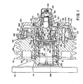
- a clutch drive generally indicated by the numeral 10 includes a support bracket 12 which is rigidly attached to a non-rotative portion of the vehicle adjacent the vehicle engine.
- the support bracket 12 includes a projecting portion 14 which mounts a spindle generally indicated by the numeral 16.
- the spindle is stepped to define a larger diameter portion 18, smaller diameter portions 20, 22 and a portion of intermediate diameter indicated generally by the numeral 24.
- a pair of bearings 26 are mounted on the larger diameter portion 18 of the spindle 16 and are locked against axial movement by a lock nut 28 which threadedly engages the portion 18 of the spindle 16 and clamps the bearings 26 against axial movement by holding them against the front face 30 of the projecting portion 14 of bracket 12.
- Another pair of bearings 32 are mounted on the smaller portions 20, 22 of the spindle 16.
- An annular cylindrical member 34 is also mounted on the smaller portion 20 of the spindle 16.
- the cylindrical member 34 and the bearings 32 are clamped against axial movement by a nut 38 which is screwed onto threaded portion 40 of the spindle 16 and which holds the cylindrical member 34 and the bearings 32 against one another and holds the inner radially extending face 42 of cylindrical member 34 against a shoulder 44 defined between the portions 20 and 24 of the spindle 16.
- a removable cap 46 protects the nut 38 and the spindle 16 against environmental contaminants.
- the cylindrical member 34 defines an inner cylindrical surface 48 which slidably receives the outer circumferential surface 50 of an annular piston 52.
- the piston 52 defines an inner circumferential surface 54 which is slidably mounted on the portion 24 of the spindle 16.
- the piston 52 cooperates with the cylindrical member 34 to define a variable volume chamber 56 therebetween.
- Fluid pressure from a suitable source (not shown), such as from the vehicle air brake system, is communicated into the chamber 56 through passages generally indicated by the numeral 58 which extend through the spindle 1G to operate the piston 52.
- the passages 58 terminate in a fitting 60 to provide a connection with the aforementioned fluid pressure source.
- the piston 52 is stepped as at 62 to define a radially extending face which receives a washer 64.
- the washer 64 is disposed between the face 62 and the front face of the inner race 66 of a bearing generally indicated by the numeral 68.
- the inner circumferential surface 70 of the race 66 is of a diameter larger than the surface 72 on the piston 52 and is also larger than the diameter of the portion 24 of the spindle 16 so that a gap is defined between the inner race 66 and the portion 72 of the piston 52 and the portion 24 of the spindle 16. Accordingly, while movement of the piston n2 will be transmitted to the bearing 68 through the washer 64, the piston 52 does not support the weight of the bearing 68.
- the inner race 66 of the bearing 68 is held against rotation relative to the spindle 16 and piston 52 by anti-rotation mechanism generally indicated by the numeral 74.
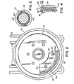
- the mechanism 74 includes a coiled spring generally indicated by the numeral 76, the coils of which are wrapped around the spindle 16.
- the end coils of the coiled spring 76 terminate in axially extending tabs 78, 80.
- the tab 78 is received within a notch 82 provided in the lock nut 28 and the tab 80 is received within a notch 84 in a collar generally indicated by the numeral 86.
- the collar 86 has an axially countersunk saddle 88 in which the notch 84 is defined.
- Collar 86 further includes an axially extending portion 90 which is pressed against the inner circumferential surface 70 of the inner race 66 of the bearing 68.
- a pulley hub generally indicated by the numeral 92 is mounted on the bearings 26 for rotation about the spindle 16.
- the pulley hub 92 is an axially fixed portion of a driving member generally indicated by the numeral 94 which consists of the pulley hub 92 and a pressure plate generally indicated by the numeral 96.
- the pressure plate 96 is an axially movable portion of the driving member 94 and, as will be described hereinafter, is mounted for movement parallel to the axis of the spindle 16.
- the pulley hub 92 is provided with pulley faces 98 which are adapted to receive belts connecting the pulley hub 92 with the engine crankshaft so that rotation of the crankshaft turns the driving member 94.
- the pulley hub 92 is also provided with circumferentially spaced bores 100 which are spaced equally about the pulley hub 92 at a predetermined radius from the axis of the spindle 16.
- the bores 100 receive circumferentially spaced pins 102 which are force fitted into the bores 100.
- the ends of the pins 102 are provided with an enlarged portion 104 which are slidably received in circumferentially spaced apertures 106 in the pressure plate 96.
- Circumferentially spaced coiled springs 108 between pulley hub 92 and pressure plate 96 yieldably urge the pressure plate 96 to the right viewing Figure 1.
- the pressure plate 96 further includes a tapered portion defining a conical surface 110.
- a conical band of friction material 112 is secured to the surface 110.
- the pressure plate 96 further includes an axially extending portion 114 which is secured to tne outer race 116 of the bearing 68.
- the bearings 32 mount a fan plate 118 for rotation about the spindle 16.
- the engine cooling fan (not shown) is secured to the fan plate 118 by bults (not shown) threaded into threaded apertures 120 in the fan plate 118.
- the fan plate 118 terminates in a conical portion 121 which defines a conical engagement surface 122 which is engaged by the friction material 112 when the clutch is engaged to provide a driving connection between the driving member 94 and the driven member or fan plate 118.
- springs 108 yieldably urge the pressure plate 96 to the right viewing Figure 1 such that the friction material 112 frictionally engages the surface 122 on the fan plate 118 so that a driving connection is provided between the driving member 94 and the driven member or fan plate 118. Accordingly, the vehicle engine turns the fan to provide engine cooling.
- a valve mechanism (not shown) is actuated to communicate fluid pressure to the fitting 60.
- the temperature sensor and valve mechanism may be of the type generally shown in U.S. Patent 4,283,009, issued August 11, 1981 to Deem.
- Fluid pressure communicated to the fitting 60 is communicated into the chamber 56 through the passages 58. Fluid pressure in the chamber 56 acts upon the piston 52, urging the latter to the left viewing Figure 1. Because of the engagement of the shoulder 62 and washer 64 with the inner race 66 of the bearing 68 which is mounted on the pressure plate 96, movement of the piston 52 also urges the pressure plate 96 to the left viewing Figure 1, thereby breaking the driving connection between the friction material 112 and the surface 122. Accordingly, while the pulley hub 92 will continue to be turned by the vehicle engine, the fan will be disconnected, so that the power used to turn the fan may be saved.
- the aforementioned temperature sensor and valve vent the fitting 60 to thereby vent the chamber 56, permitting the springs 108 to again urge the pressure plate 96 and the piston 52 to the right viewing the figure, thereby re-engaging the friction material 112 with the surface 122 to again provide a driving connection between the pulley hub 92 and the fan plate 118.
- the springs 108 will maintain the clutch members engaged, so that the clutch is "fail-safe".
- the inner race 66 of the bearing 68 is prevented from rotation by the aforementioned anti-rotation mechanism 74. Without the mechanism 74, the inner race 66 would tend to rotate with the pressure plate, and, because of the engagement of the inner race 66 with the piston 52, rotation of the inner race would also tend to rotate the piston 52 on the spindle 16, thereby perhaps causing the 0 ring seals to fail prematurely. Such rotation of the piston 52 is prevented by the anti-rotation mechanism 74.
- the spring 76 collapses to accommodate axial movement of the pressure plate 96.
Landscapes
- Engineering & Computer Science (AREA)
- General Engineering & Computer Science (AREA)
- Mechanical Engineering (AREA)
- Physics & Mathematics (AREA)
- Fluid Mechanics (AREA)
- Chemical & Material Sciences (AREA)
- Combustion & Propulsion (AREA)
- Hydraulic Clutches, Magnetic Clutches, Fluid Clutches, And Fluid Joints (AREA)
- Mechanical Operated Clutches (AREA)
Applications Claiming Priority (2)
| Application Number | Priority Date | Filing Date | Title |
|---|---|---|---|
| US06/473,427 US4541516A (en) | 1983-03-09 | 1983-03-09 | Clutch drive with antirotation spring |
| US473427 | 1983-03-09 |
Publications (3)
| Publication Number | Publication Date |
|---|---|
| EP0118371A2 true EP0118371A2 (de) | 1984-09-12 |
| EP0118371A3 EP0118371A3 (en) | 1984-11-07 |
| EP0118371B1 EP0118371B1 (de) | 1988-05-11 |
Family
ID=23879478
Family Applications (1)
| Application Number | Title | Priority Date | Filing Date |
|---|---|---|---|
| EP84400456A Expired EP0118371B1 (de) | 1983-03-09 | 1984-03-07 | Kupplungsgetriebe mit rotationshindernder Feder |
Country Status (8)
| Country | Link |
|---|---|
| US (1) | US4541516A (de) |
| EP (1) | EP0118371B1 (de) |
| JP (1) | JPS59166722A (de) |
| AU (1) | AU568333B2 (de) |
| BR (1) | BR8401165A (de) |
| CA (1) | CA1207617A (de) |
| DE (1) | DE3471139D1 (de) |
| MX (1) | MX157700A (de) |
Cited By (2)
| Publication number | Priority date | Publication date | Assignee | Title |
|---|---|---|---|---|
| WO1989002992A1 (en) * | 1987-09-25 | 1989-04-06 | Allied-Signal Inc. | Fan clutch |
| WO1993012355A1 (en) * | 1991-12-16 | 1993-06-24 | Allied-Signal Inc. | Clutch drive mechanism |
Families Citing this family (17)
| Publication number | Priority date | Publication date | Assignee | Title |
|---|---|---|---|---|
| US4638900A (en) * | 1985-06-17 | 1987-01-27 | Allied Corporation | Fan drive mechanism |
| FR2730532B1 (fr) * | 1995-02-09 | 1997-04-04 | Valeo | Butee de debrayage a commande hydraulique pour embrayage a diaphragme, notamment pour vehicule automobile comportant un manchon de guidage |
| US6092638A (en) * | 1998-03-05 | 2000-07-25 | Horton, Inc. | Splineless rotational control apparatus |
| CN1316175C (zh) * | 1999-05-17 | 2007-05-16 | 霍顿公司 | 无花键旋转控制装置 |
| US20040159524A1 (en) * | 2003-02-14 | 2004-08-19 | Carpenter David E. | Cone-clutched assembly |
| US7137333B2 (en) * | 2004-10-19 | 2006-11-21 | Borgwarner Inc. | Single-piece electro-polished air cylinder for a fluid coupling device |
| US7104382B2 (en) * | 2004-10-21 | 2006-09-12 | Kit Masters Inc. | Clutch system |
| US7438169B2 (en) | 2004-10-21 | 2008-10-21 | Kit Masters Inc. | Clutch system |
| US8100239B2 (en) * | 2008-01-18 | 2012-01-24 | Kit Masters Inc. | Clutch device and methods |
| US8529387B2 (en) * | 2008-04-30 | 2013-09-10 | Dayco Ip Holdings, Llc | Pulley with asymmetric torque-sensitive clutching |
| US8784244B2 (en) * | 2008-04-30 | 2014-07-22 | Dayco Ip Holdings, Llc | Pulley with asymmetric torque-sensitive clutching |
| WO2010056830A2 (en) | 2008-11-12 | 2010-05-20 | Horton, Inc. | Two-speed clutch and retro-fit kit |
| US8109375B2 (en) * | 2009-05-07 | 2012-02-07 | Kit Masters Inc. | Clutch systems and methods |
| DE102009038767B4 (de) * | 2009-08-27 | 2014-11-27 | Kendrion Linnig Gmbh | Reibschaltkupplung zur Betätigung mit einem strömungsfähigen Druckmittel |
| US9046137B2 (en) | 2010-01-22 | 2015-06-02 | Kit Masters Inc. | Fan clutch apparatus and methods |
| US8360219B2 (en) | 2010-04-26 | 2013-01-29 | Kit Masters, Inc. | Clutch system and methods |
| US8888627B2 (en) | 2010-05-25 | 2014-11-18 | Dayco Ip Holdings, Llc | One-way damped over-arm tensioner |
Family Cites Families (14)
| Publication number | Priority date | Publication date | Assignee | Title |
|---|---|---|---|---|
| US2104962A (en) * | 1936-08-24 | 1938-01-11 | Borg Warner | Friction clutch |
| US2308681A (en) * | 1939-11-13 | 1943-01-19 | Clarence M Eason | Clutch |
| US2684742A (en) * | 1949-07-26 | 1954-07-27 | Ind Clutch Corp | Air operated clutch with interchangeable air operated power unit |
| US3145816A (en) * | 1961-08-21 | 1964-08-25 | Gen Motors Corp | Clutches |
| US3467071A (en) * | 1965-07-15 | 1969-09-16 | Dynair Ltd | Thermally-responsive control mechanisms |
| GB1310511A (en) * | 1969-06-25 | 1973-03-21 | Dynair Ltd | Rotary transmission devices |
| GB1377476A (en) * | 1970-11-21 | 1974-12-18 | Dynair Ltd | Fan drives |
| GB1376904A (en) * | 1971-03-11 | 1974-12-11 | Dynair Ltd | Rotary fans |
| US3985214A (en) * | 1974-12-04 | 1976-10-12 | The Bendix Corporation | Fan clutch drive |
| US4226095A (en) * | 1978-10-19 | 1980-10-07 | Horton Manufacturing Company, Inc. | Mechanism for maintaining contact between the driving side of torque transfering surfaces of a first rotatable member and the driven side of matching torque transfering surfaces of a second rotatable member |
| FR2453335A1 (fr) * | 1979-04-02 | 1980-10-31 | Ferodo Sa | Transmission a organe d'accouplement hydraulique et embrayage de verrouillage, notamment pour vehicule automobile |
| US4283009A (en) * | 1980-02-07 | 1981-08-11 | The Bendix Corporation | Control valve for fluid-operated clutch |
| US4355710A (en) * | 1980-08-25 | 1982-10-26 | Horton Industries, Inc. | Spring engaged fluid released fan clutch for a live shaft |
| DE3145363C2 (de) * | 1981-11-14 | 1984-12-13 | Skf Kugellagerfabriken Gmbh, 8720 Schweinfurt | Hydraulisch betätigte Ausrückvorrichtung |
-
1983
- 1983-03-09 US US06/473,427 patent/US4541516A/en not_active Expired - Lifetime
- 1983-11-10 CA CA000440958A patent/CA1207617A/en not_active Expired
-
1984
- 1984-02-23 AU AU24883/84A patent/AU568333B2/en not_active Ceased
- 1984-03-02 MX MX200543A patent/MX157700A/es unknown
- 1984-03-07 EP EP84400456A patent/EP0118371B1/de not_active Expired
- 1984-03-07 DE DE8484400456T patent/DE3471139D1/de not_active Expired
- 1984-03-09 BR BR8401165A patent/BR8401165A/pt not_active IP Right Cessation
- 1984-03-09 JP JP59044169A patent/JPS59166722A/ja active Granted
Cited By (2)
| Publication number | Priority date | Publication date | Assignee | Title |
|---|---|---|---|---|
| WO1989002992A1 (en) * | 1987-09-25 | 1989-04-06 | Allied-Signal Inc. | Fan clutch |
| WO1993012355A1 (en) * | 1991-12-16 | 1993-06-24 | Allied-Signal Inc. | Clutch drive mechanism |
Also Published As
| Publication number | Publication date |
|---|---|
| BR8401165A (pt) | 1984-10-16 |
| JPH0477806B2 (de) | 1992-12-09 |
| US4541516A (en) | 1985-09-17 |
| AU568333B2 (en) | 1987-12-24 |
| MX157700A (es) | 1988-12-09 |
| AU2488384A (en) | 1984-09-13 |
| EP0118371A3 (en) | 1984-11-07 |
| DE3471139D1 (en) | 1988-06-16 |
| EP0118371B1 (de) | 1988-05-11 |
| CA1207617A (en) | 1986-07-15 |
| JPS59166722A (ja) | 1984-09-20 |
Similar Documents
| Publication | Publication Date | Title |
|---|---|---|
| US4483430A (en) | Clutch drive | |
| US4541516A (en) | Clutch drive with antirotation spring | |
| EP0122015B1 (de) | Luftkompressor | |
| JPH0451689B2 (de) | ||
| US4913276A (en) | Clutch releasing apparatus | |
| WO1999064756A1 (en) | Clutch assembly | |
| US4515258A (en) | Clutch drive with link spring | |
| CA1301092C (en) | Fan clutch | |
| US5215175A (en) | Clutch drive mechanism | |
| US4482038A (en) | Double active drive mechanism | |
| WO2000070236A2 (en) | Rotational control apparatus | |
| US4848549A (en) | Coaxial adjustable hydraulic clutch actuator | |
| US4708229A (en) | Double acting clutch | |
| JPS63500816A (ja) | ファン駆動機構 | |
| EP0270713B1 (de) | Verdichteraggregat | |
| WO1992001874A1 (en) | A friction clutch | |
| US4125180A (en) | Disconnect mechanism for compressor drive | |
| GB2176255A (en) | Multi-plate clutch in air compressor | |
| JPH0784902B2 (ja) | 可動プーリ | |
| RU1827434C (ru) | Привод компрессора транспортного средства | |
| JPS5840252Y2 (ja) | クラッチ付ファン駆動装置 | |
| JPS6129418B2 (de) | ||
| JP2000320570A (ja) | クラッチディスク摩耗検出装置、オペレーティングシリンダー、クラッチディスク摩耗検出システム及びクラッチ |
Legal Events
| Date | Code | Title | Description |
|---|---|---|---|
| PUAI | Public reference made under article 153(3) epc to a published international application that has entered the european phase |
Free format text: ORIGINAL CODE: 0009012 |
|
| PUAL | Search report despatched |
Free format text: ORIGINAL CODE: 0009013 |
|
| AK | Designated contracting states |
Designated state(s): DE FR GB IT SE |
|
| AK | Designated contracting states |
Designated state(s): DE FR GB IT SE |
|
| 17P | Request for examination filed |
Effective date: 19850410 |
|
| 17Q | First examination report despatched |
Effective date: 19860619 |
|
| RAP1 | Party data changed (applicant data changed or rights of an application transferred) |
Owner name: ALLIED CORPORATION |
|
| ITF | It: translation for a ep patent filed | ||
| GRAA | (expected) grant |
Free format text: ORIGINAL CODE: 0009210 |
|
| AK | Designated contracting states |
Kind code of ref document: B1 Designated state(s): DE FR GB IT SE |
|
| REF | Corresponds to: |
Ref document number: 3471139 Country of ref document: DE Date of ref document: 19880616 |
|
| EN | Fr: translation not filed | ||
| PLBE | No opposition filed within time limit |
Free format text: ORIGINAL CODE: 0009261 |
|
| STAA | Information on the status of an ep patent application or granted ep patent |
Free format text: STATUS: NO OPPOSITION FILED WITHIN TIME LIMIT |
|
| 26N | No opposition filed | ||
| ET | Fr: translation filed | ||
| REG | Reference to a national code |
Ref country code: FR Ref legal event code: BR |
|
| ITTA | It: last paid annual fee | ||
| PGFP | Annual fee paid to national office [announced via postgrant information from national office to epo] |
Ref country code: SE Payment date: 19920319 Year of fee payment: 9 |
|
| PG25 | Lapsed in a contracting state [announced via postgrant information from national office to epo] |
Ref country code: SE Effective date: 19930308 |
|
| EUG | Se: european patent has lapsed |
Ref document number: 84400456.4 Effective date: 19931008 |
|
| PGFP | Annual fee paid to national office [announced via postgrant information from national office to epo] |
Ref country code: GB Payment date: 19970205 Year of fee payment: 14 |
|
| PGFP | Annual fee paid to national office [announced via postgrant information from national office to epo] |
Ref country code: FR Payment date: 19970307 Year of fee payment: 14 |
|
| PGFP | Annual fee paid to national office [announced via postgrant information from national office to epo] |
Ref country code: DE Payment date: 19970326 Year of fee payment: 14 |
|
| PG25 | Lapsed in a contracting state [announced via postgrant information from national office to epo] |
Ref country code: GB Free format text: LAPSE BECAUSE OF NON-PAYMENT OF DUE FEES Effective date: 19980307 |
|
| PG25 | Lapsed in a contracting state [announced via postgrant information from national office to epo] |
Ref country code: FR Free format text: THE PATENT HAS BEEN ANNULLED BY A DECISION OF A NATIONAL AUTHORITY Effective date: 19980331 |
|
| GBPC | Gb: european patent ceased through non-payment of renewal fee |
Effective date: 19980307 |
|
| PG25 | Lapsed in a contracting state [announced via postgrant information from national office to epo] |
Ref country code: DE Free format text: LAPSE BECAUSE OF NON-PAYMENT OF DUE FEES Effective date: 19981201 |
|
| REG | Reference to a national code |
Ref country code: FR Ref legal event code: ST |