EP0118569A2 - Stereoskopisches Betrachtungsgerät - Google Patents
Stereoskopisches Betrachtungsgerät Download PDFInfo
- Publication number
- EP0118569A2 EP0118569A2 EP82402406A EP82402406A EP0118569A2 EP 0118569 A2 EP0118569 A2 EP 0118569A2 EP 82402406 A EP82402406 A EP 82402406A EP 82402406 A EP82402406 A EP 82402406A EP 0118569 A2 EP0118569 A2 EP 0118569A2
- Authority
- EP
- European Patent Office
- Prior art keywords
- film
- plane
- mirrors
- mirror
- examined
- Prior art date
- Legal status (The legal status is an assumption and is not a legal conclusion. Google has not performed a legal analysis and makes no representation as to the accuracy of the status listed.)
- Withdrawn
Links
Images



Classifications
-
- G—PHYSICS
- G01—MEASURING; TESTING
- G01C—MEASURING DISTANCES, LEVELS OR BEARINGS; SURVEYING; NAVIGATION; GYROSCOPIC INSTRUMENTS; PHOTOGRAMMETRY OR VIDEOGRAMMETRY
- G01C11/00—Photogrammetry or videogrammetry, e.g. stereogrammetry; Photographic surveying
- G01C11/04—Interpretation of pictures
- G01C11/06—Interpretation of pictures by comparison of two or more pictures of the same area
- G01C11/12—Interpretation of pictures by comparison of two or more pictures of the same area the pictures being supported in the same relative position as when they were taken
- G01C11/14—Interpretation of pictures by comparison of two or more pictures of the same area the pictures being supported in the same relative position as when they were taken with optical projection
-
- G—PHYSICS
- G02—OPTICS
- G02B—OPTICAL ELEMENTS, SYSTEMS OR APPARATUS
- G02B30/00—Optical systems or apparatus for producing three-dimensional [3D] effects, e.g. stereoscopic images
- G02B30/20—Optical systems or apparatus for producing three-dimensional [3D] effects, e.g. stereoscopic images by providing first and second parallax images to an observer's left and right eyes
- G02B30/34—Stereoscopes providing a stereoscopic pair of separated images corresponding to parallactically displaced views of the same object, e.g. three-dimensional [3D] slide viewers
- G02B30/35—Stereoscopes providing a stereoscopic pair of separated images corresponding to parallactically displaced views of the same object, e.g. three-dimensional [3D] slide viewers using reflective optical elements in the optical path between the images and the observer
Definitions
- the present invention relates to a stereoscopic viewer intended for the simultaneous examination of two successive images of a film of panoramic shots produced in particular from an aerial photography apparatus.
- a viewer of this kind is generally placed above a translucent planar support on which the film of panoramic shots is placed flat, suitable lighting being placed below the translucent planar support. It comprises, in a known manner, between two objectives turned on the side of the film to be observed and two eyepieces, optical means making it possible to simultaneously examine two successive panoramic images of the film, as well as adjustment means making it possible to move one of the two images received by the observer in relation to the other.
- a stereoscopic viewer allows you to watch a film taken from a camera carried by an airplane.
- the camera is oriented downwards and during shooting, it can pivot around an axis parallel to the direction of advance of the aircraft.
- the camera is moved relative to the airplane pilot from left to right or from right to left so that on each of the panoramic images of the film, there are at the ends of the same image, in the longitudinal direction of the film; the right horizon and the left horizon of the landscape over which the plane is moving. It follows that, for a film of panoramic shots, the images, all impressed-start, in a longitudinal direction of the film, by the right horizon and, consequently, in the opposite longitudinal direction, by the horizon left.
- the viewer which is the subject of United States of America patent 4,221,462 makes it possible to avoid such cutting. It comprises means making it possible to move one of the two images received by the observer transversely with respect to the other in order to obtain the merging thereof.
- the purpose of such adjustment means is to correct the well-known distortion resulting from the fact that, between two successive photographs, the image of a point situated vertically on the plane, is moved transversely in the plane of the film clearly faster than images of points on the right horizon or the left horizon. This relative displacement of the image points which is due to the movement of the shooting plane, is a function of the speed and the height of said plane.
- the present invention aims to remedy the aforementioned drawback, and for this purpose, it proposes to produce a stereoscopic viewer of the type indicated above allowing adjustment of the relative position of the two images received by the observer which is particularly simple, using a very small number of uncomplicated mechanical components.
- Another object of the invention is also to provide a stereoscopic viewer which is practical, safe and of a small footprint.
- the present invention therefore relates to a stereoscopic viewer of aerial photographs, said viewer being intended to be placed in front of a film of panoramic shots to be examined, said film being placed flat and being suitably lit, said vision neuse comprising, firstly, optical means making it possible to examine simultaneously, from two eyepieces of substantially parallel axes, the homologous points of two successive panoramic photographs of the film to be examined, said means defining an optical path between each of the two aforementioned photographs and one of the observer's eyes, and secondly, adjustment means making it possible to move one of the two images received by the observer relative to the other, characterized in that the means optics comprise, for each optical path, on the one hand, a set of plane mirrors and, on the other hand, a rotator system capable of rotating the images substantially around the line of sight of the corresponding eye, l assembly ensuring an even number of reflections and that the adjustment means comprise members allowing the pivoting of at least one of the two rotator systems around a fixed axis and / or the displacement
- the image rotator system is a prism with total reflection; in this case, it is preferred that each prism is a straight prism based on an isosceles right triangle, the total reflection faces being substantially perpendicular to the plane of the film to be examined.
- the image rotator system is a so-called "Pechan" system comprising two prisms on which five reflections are made.
- the adjustment means comprise members allowing the pivoting of at least one of the two prisms around an axis parallel to its edge opposite to the face of total reflection; in the case of a right prism with a rectangular isosceles base, the pivot axis is advantageously coincident with the edge of the right dihedral of the prism.
- the axes of the two eyepieces are advantageously arranged in a plane substantially parallel to the longitudinal axis of the film to be examined.
- the face with total reflection is substantially perpendicular to the longitudinal axis of the film and the prism is rotated relative to its edge opposite the reflecting face total, a transverse displacement of the zone examined is carried out on the corresponding image of the film and this therefore makes it possible to compensate for the displacement of the homologous points on two successive panoramic images.
- the other prism is rotated around its edge opposite the total reflection face and substantially parallel to the longitudinal axis of the film, the zone examined on the film is displaced along the axis of the film. corresponding image of the film, which can be useful if the length of the images in the film is slightly modified.
- the distance between the axes of the two eyepieces of the viewer according to the invention is adjusted to the spacing of the eyes, that is to say approximately 65 mm. Under these conditions, the two parallel incident beams, which strike the two rotator systems, are therefore spaced about 65 mm apart.
- the viewer according to the invention is used for examining films whose image periodicity is significantly higher, for example 250 mm; the two inputs of the optical paths of the viewer are turned towards two successive panoramic images of the film and are therefore spaced from each other by a distance substantially equal to the aforementioned periodicity of the images of the film.
- the second mirrors are pivotally mounted around an axis parallel to the edge of intersection of their planes. This allows a transverse displacement of the homologous zones examined on two successive images.
- An overall transverse adjustment can also be achieved by transversely moving the entire viewer relative to the film. This transverse positioning of the viewer can be facilitated by a bracket system or, by a rail system extending transversely relative to the film and on which the viewer is mounted.
- the third mirrors are advantageously fixed and united in a single element whose reflective face forms an angle of approximately 135 ° relative to the plane of the film to be examined.
- FIG. 1 represents a film of panoramic shots and two successive images of this film have been designated by 101 and 102.
- On each image there is, by moving from the left to the right in FIG. 1, an area of sky designated by the index a, the left horizon designated by the index b, the area of terrestrial photography corresponding to the scan to the right of the camera designated by the index c, the right horizon designated by the index d and finally a sky area designated by the index e.
- These five elements are found on each of the successive images of the film in the order indicated above and in FIG.
- M 1 and P 1 two points of the photograph 101 located near each of the two horizons and by M 2 and P 2 the two homologous points of the photograph 102.
- the images 201 are represented, 202 views by an observer in the viewer according to the first variant. These images 201, 202 of the photographs 101 and 102 respectively show the left horizons 201b, 202b with the sky above the horizon line, while the opposite occurs for the right horizons 201d and 202d.
- the observer placed on the side of the viewer, where the arrow F is located sees in the eyepieces a normal representation, for the images P ' 1 and P l 2 of the points P 1 and P 2 with respect to which the sky is positioned in a normal way, while it sees an upside-down representation for the images M ' 1 and M' 2 of the points M 1 and M 2 with respect to which the sky is placed downwards.
- the second alternative embodiment aims to remedy the aforementioned drawback by providing a viewer which includes a device allowing the image to be turned over without the observer moving from his station.
- the observer thus examines half of the panorama with a first position of the reversal device and, before examining the other half, he proceeds to flip the image to also benefit from this vision on the other half. place.
- the second variant of the stereoscopic viewer is characterized in that first of all, the sets of plane mirrors associated with each of the two optical paths each include m mirrors, which bring the rays coming from two homologous points two successive panoramic photographs to be dropped in parallel but in the opposite direction onto two parallel, integral turning mirrors, placed back to back and capable of pivoting 90 ° around an axis perpendicular to the incident rays; and secondly, the set of mirrors of each optical path comprises one of said reversing mirrors followed, along the optical path, by p mirrors which send the rays, which are reflected on the reversing mirror, towards the rotator system associated with each eyepiece, m and p being positive integers.
- the image rotator system is a prism with total reflection and (m + p) is an even number; the pivot axis of the two turning mirrors is advantageously perpendicular to the plane of the film to be examined; to avoid excessive congestion, the viewer, for each optical path, comprises three mirrors between the film and the reversal mirror, these three mirrors being successively formed from the film to be examined, firstly, a first mirror disposed substantially at 45 ° relative to the plane of the film, substantially perpendicular to the longitudinal plane of symmetry of the film, the reflecting surface of said mirror being turned towards the side of said film, secondly, by a second mirror receiving the rays, which have reflected on the first, this second mirror making an angle close to 45 ° with the longitudinal axis of the film and an angle (90 ° + ⁇ ) with the plane of the film to be examined, paying substantially the same low positive value for the two paths optical, the planes of the second mirrors of the two optical paths having substantially parallel traces on
- the viewer according to this second variant comprises a single mirror between the turning mirror and the eye of the observer, this fourth mirror receiving the rays of the turning mirror;
- the mirror plans of reversal are substantially perpendicular to the plane of the film and their traces in the plane of the film are approximately 45 ° with the longitudinal axis of the film;
- the traces in the film plane of the planes of the fourth mirrors are substantially perpendicular to the axis of the film and the viewing axes corresponding to the two eyes of the observer are substantially perpendicular to the plane of the film.
- means are advantageously provided for adjusting the rotation of the images received by the observer; these means comprise members allowing the prisms to pivot about an axis perpendicular to their edges opposite the total reflection faces.
- the viewer according to the invention can be easily adjusted to adapt to the length corresponding to the image periodicity of different films by moving more or less that of the first two mirrors, which is mounted to slide. compared to each other.
- each rotator system and one of the eyes of the observer one can place a converging lens returning the received image to infinity, the focus of said lens being on the film to be examined.
- an afocal magnification multiplier assembly the coefficient of the afocal assembly used can be, for example, between 2 to 8. More generally, on each optical path, it is possible to provide a set of lenses making it possible to increase the magnification.
- This procedure is particularly useful for the viewer of the second variant because, compared to the viewer of the first variant, the length of the optical path has been increased, which results in decrease in magnification; the objective, possibly associated with a field lens, provides an image of the aerial photography examined and the eyepiece makes it possible to view said image.
- FIG. 6 shows two successive photographic images I 1 and 1 2 of a film, which was taken by a panoramic camera mounted on an airplane.
- the plane moves in direction D, while the film inside the camera is unwound in direction D '.
- the camera is oriented downwards, and, during the shooting, it pivots in a vertical plane around an axis parallel to the direction of advance D of the airplane.
- the camera will be moved for a shot, according to a scanning movement going from the right horizon to the left horizon. .
- the central part corresponds to the shooting operated by the camera when it was pointed vertically downwards, while the image borders perpendicular to the axis of the film each corresponds, at the beginning or at the end of the camera's scanning stroke, when the latter is pointed on the right or left horizon.
- x 1 is an image point of the right horizon (relative to the pilot of the aircraft)
- z1 which is located in the vicinity of the opposite border is an image point of the left horizon and y 1 located on the transverse median axis of the panoramic image I 1 is the nadiral image point.
- a light table of known type has been designated by 1, comprising a side wall 2 surmounted by a horizontal translucent glass plate 3; lighting (not shown) is placed under this glass plate.
- two openings are formed constituting the inputs of the two optical paths of the viewer 10, which are assigned to two successive panoramic images Il and I 2 to examine.
- a mirror 21a, 21b To the right of each of the above-mentioned openings is placed a mirror 21a, 21b respectively; the two mirrors 21a, 21b are arranged symmetrically with respect to a vertical plane perpendicular to the plane of the film to be examined, their reflective surfaces being turned towards one another; they are each arranged at 45 ° relative to the plane of the film and the intersection edge of their planes is perpendicular to the longitudinal axis of the film.
- the projections of the centers of the two mirrors 21a, 21b on the plane of the film have been designated by n 'and n'; the spacing between the two projections n ′ 1 and n ′ is substantially equal to the length of the panoramic images of the film 14 and, consequently, significantly greater than the spacing between the two eyepieces 12.
- the two mirrors 21a and 21b are advantageously mounted on longitudinal slides (not shown) inside the housing 11, so as to be able to adjust their spacing as a function of the length of the panoramic images of different films.
- each mirror 22a, 22b is arranged in a vertical plane making an angle of 45 ° relative to the longitudinal axis of the film 14.
- the two mirrors 22a, 22b form a right dihedron having a vertical edge 26; the two mirrors 22a, 22b are advantageously mounted to pivot about an axis passing through their common vertical edge 26 so as to be able to slightly vary the angle of 45 ° which they make with the axis of the film to be examined, while keeping the same plane of symmetry.
- the light rays returned by the mirrors 21a, 21b are reflected by the two associated mirrors 22a, 22b and returned to a common fixed mirror 23, the reflecting face of which makes an angle of 135 ° relative to the plane of the film 14.
- the mirror 23 receives two parallel light beams reflected by the pair of mirrors 22a, 22b and returns them vertically upwards towards two prisms 24a, 24b.
- the mirrors 21a, 21b, 22a, 22b and the common mirror 23 constitute an optical system making it possible to bring together the two incident light beams coming from the two parts of the examined images and which are separated from one another. the other about 250mm, so that these two beams, at the exit of the system, are only about 65mm apart, a value which corresponds to the average spacing of the eyes of an observer.
- the two prisms 24a and 24b are identical straight prisms arranged on either side of the vertical plane of symmetry of the mirrors 21a, 21b, 22a, 22b.
- the base of the prisms 24a, 24b is an isosceles right triangle; their two hypotenuse faces are placed perpendicular to the plane of the film 14; they make an angle of 90 ° between them.
- the hypotenuse face of the prism 24a is perpendicular to the longitudinal axis of the film 14.
- the light rays reflected by the mirror 23 penetrate through one of the two faces of the right dihedral, are reflected by the hypotenuse face and exit through the other face of the right dihedral.
- the light rays which pass through the two prisms 24a, 24b do not undergo any deviation.
- two vertical emerging beams are obtained having the same spacing as the two incident vertical beams; these beams are directed, each on a converging lens 25a, 25b placed inside the eyepieces 12.
- the two converging lenses 25a, 25b return the image to infinity, their focus being arranged in the plane of the film 14 while holding account of the optical path.
- the optical system of the stereoscopic viewer can be completed by two afocal magnification multiplier assemblies (not shown) placed between the converging lenses 25a, 25b and the eyes of the observer.
- the magnification of the sets used can range from 2 to 8.
- One of the essential characteristic elements of the stereoscopic viewer 10 resides in the ease of relative transverse adjustment of the two images received by the observer: in fact, to cancel, for the area observed, the transverse offset of the homologous bridges of the two images examined, the observer modifies the inclination of the hypotenuse face of the prism 24a by rotating it around its opposite horizontal edge.
- This variation of the inclination of the prism P can be achieved by very simple mechanical means, such as an axis disposed along the edge of said prism and integral with the prism, this axis extending, for example, outside the housing. 11 by an operating button.
- the image area observed through the prism 24a is thus displaced on the film while that observed through 24b remains fixed, which makes it possible to compensate for the transverse offset of the homologous points.
- the overall transverse adjustment of the stereoscopic viewer with respect to the film that is to say the simultaneous transverse adjustment of the two images received by the observer can, of course, be obtained by moving transversa The viewer 10 relative to the film. It is also possible to obtain a transverse adjustment by slightly pivoting the associated mirrors 22a, 22b about an axis parallel to their intersection edge 26.
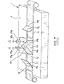
- each of the openings of the housing 11, which constitute the inputs of the two optical paths of the viewer, is placed a plane mirror 320a, 320b respectively; the two mirrors 320a, 320b are arranged symmetrically with respect to a vertical plane perpendicular to the plane of the film to be examined and perpendicular to the axis of said film; the reflecting surfaces of the two mirrors 320a, 320b are turned towards one another, these two mirrors being arranged at 45 ° relative to the plane of the film 14.
- a ray which leaves a point of the film 14 perpendicular to this film is reflected on one of the first mirrors 320a, 320b and is brought back towards the center of the viewer where it meets a second plane mirror 321a or 321b.
- These second mirrors are in planes, which cut the plane of the film 14 along parallel tracks making an angle of 45 ° with the axis of the film 14.
- the planes of each of the mirrors 32la and 321b make with the plane of the film 14, an angle of 95 °, this angle being counted between the reflecting face of the mirror and the half-plane of the film where the first corresponding mirror is located.
- the two second mirrors form between them in a 10 ° dihedral angle.
- the reflection of the rays coming from the first mirrors is effected with a change in level, the ray reflected on the second mirror being directed upwards, that is to say deviating from the film 14.
- This ray then meets a third plane mirror 322a, 322b respectively.
- the planes of the third mirrors intersect the plane of the film 14 along lines parallel to the axis of the film 14; the planes of the two third mirrors form, with the plane of the film 14, an angle of approximately 85 °, the reflecting faces being slightly inclined downward, that is to say towards the film 14.
- the inclination of the mirrors 322a and 322b brings the ray which comes from the second mirrors into a plane parallel to the plane of the film 14.
- the beams leaving the third mirrors are therefore horizontal and directed, for the two optical paths, towards the median longitudinal plane of the film 14.
- the whole set of mirrors which has just been described, is symmetrical with respect to the common perpendicular to the longitudinal axis of the film, on the one hand, and the edge of the dihedron formed by the second mirrors 321a, 321b on the other hand: this common perpendicular has been designated by ⁇ .
- Two pivoting mirrors 323a, 323b are pivoted about the axis ⁇ , which are mounted on the same mobile assembly and which are placed back to back.
- the two turning mirrors 323a, 323b receive the rays respectively from the third mirrors 322a, 322b and they return them respectively to a fourth plane mirror 324a, 324b.
- the turning mirrors 323a, 323b are perpendicular to the plane of the film 14 and form an angle of 45 ° with the longitudinal axis of the film 14; the mobile assembly which carries them is capable of taking two positions at 90 °, one of the other. For one of the positions, shown in FIG. 8, the mirror 323b returns the light beam coming from 322b to the mirror 324b; for the other position, the mirror 323a returns the light beam from 322b to the mirror 324a.
- the fourth mirrors 324a, 324b make an angle of 45 ° with the plane of the film 14, the reflecting faces being directed upwards; the traces of the corresponding planes on the film plane form a right angle with the longitudinal axis of the film.
- this prism is a straight prism with a rectangular isosceles base which can rotate, on the one hand, around an axis passing through the hypotenuse face and perpendicular to the plane of the film 14 and, on the other hand, around an axis arranged along the edge opposite to the hypothenuse face where the total reflection takes place, said edge being parallel to the plane of the film 14.
- the adjustment of the device is such that the hypotenuse faces are substantially perpendicular to the plane of the film 14.
- a converging objective 326a, 326b is interposed which provides the film examined with an image which is looked at through an eyepiece 327a, 327b disposed on each optical path between the prism 325a, 325b and the eyes 328a, 328b of the observer.
- lens systems 326a, 327a or 326b, 327b makes it possible to obtain a magnification of 2 to 8, although the optical paths have been lengthened compared to the device described in the first variant.
- one of the advantages of the viewer according to the invention lies in the ease of the relative transverse adjustment of the two images received by the observer: in fact, to cancel, for the zone observed, the transverse offset homologous points of two images examined, the observer modifies the inclination of the hypotenuse face of one of the prisms 325a or 325b by rotating it around its horizontal edge opposite the hypotenuse face.
- This variation of the inclination of the prisms can be achieved by very simple mechanical means such as an axis disposed along the edge of said prism and integral with the prism, this axis extending outside the housing 311 by an operating button.
- the overall transverse adjustment of the viewer relative to the film is obtained by moving the viewer transversely relative to said film.
- the adjustment of the angle formed by the hypotenuse faces of the two prisms 325a, 325b allows relative angular adjustment of the two images forming the stereoscopic vision.
- the embodiments described above are in no way limiting and may give rise to any desirable modifications, without departing from the scope of the invention.
- the adjustments can be obtained by acting not on the prisms but on at least one of the mirrors and in particular, for the second variant, by acting on the turning mirrors.
- at least one of the view mirrors of the viewer according to the invention can pivot around a straight line parallel to its plane or contained in its plane.
Landscapes
- Physics & Mathematics (AREA)
- General Physics & Mathematics (AREA)
- Engineering & Computer Science (AREA)
- Optics & Photonics (AREA)
- Multimedia (AREA)
- Radar, Positioning & Navigation (AREA)
- Remote Sensing (AREA)
- Stereoscopic And Panoramic Photography (AREA)
Applications Claiming Priority (2)
| Application Number | Priority Date | Filing Date | Title |
|---|---|---|---|
| FR8221225A FR2538129A2 (fr) | 1981-07-08 | 1982-12-17 | Visionneuse stereoscopique a retournement d'image |
| FR8221225 | 1982-12-17 |
Publications (2)
| Publication Number | Publication Date |
|---|---|
| EP0118569A2 true EP0118569A2 (de) | 1984-09-19 |
| EP0118569A3 EP0118569A3 (de) | 1985-11-21 |
Family
ID=9280232
Family Applications (1)
| Application Number | Title | Priority Date | Filing Date |
|---|---|---|---|
| EP82402406A Withdrawn EP0118569A3 (de) | 1982-12-17 | 1982-12-31 | Stereoskopisches Betrachtungsgerät |
Country Status (1)
| Country | Link |
|---|---|
| EP (1) | EP0118569A3 (de) |
Family Cites Families (4)
| Publication number | Priority date | Publication date | Assignee | Title |
|---|---|---|---|---|
| US2391675A (en) * | 1943-02-11 | 1945-12-25 | Leo H Brown | Stereoscope |
| US2866382A (en) * | 1957-09-09 | 1958-12-30 | Bausch & Lomb | Stereoscopic viewing device |
| US3495891A (en) * | 1967-12-18 | 1970-02-17 | Itek Corp | Floating mark systems in a stereoscopic device |
| CH600305A5 (en) * | 1976-06-29 | 1978-06-15 | Yzerman Henk | Stereo-evaluator for aerial photographs |
-
1982
- 1982-12-31 EP EP82402406A patent/EP0118569A3/de not_active Withdrawn
Also Published As
| Publication number | Publication date |
|---|---|
| EP0118569A3 (de) | 1985-11-21 |
Similar Documents
| Publication | Publication Date | Title |
|---|---|---|
| EP0207837A1 (de) | Photographischer Apparat für Stereoaufnahmen | |
| CH340416A (fr) | Machine à composer photographique | |
| FR2673007A1 (fr) | Dispositif de correction de la parallaxe et/ou de la vergence d'un appareil photo. | |
| CH404236A (fr) | Dispositif de contrôle de la mise au point d'un objectif de prise de vues par l'examen de l'image observée à travers un viseur reflex accouplé à cet objectif | |
| EP0121962B1 (de) | Vorrichtung zur optischen Kopplung zwischen Lichtwellenleitern | |
| FR2771516A1 (fr) | Dispositif formant guide de masquage pour dispositives stereoscopiques | |
| FR2747805A1 (fr) | Appareil photographique stereoscopique de type reflex a viseur unique | |
| EP0407519A1 (de) | Interferometrische aufstellung für fourier-multiplexierte durchlaufspektralabbildungsvorrichtung und spektralabbildungen mit solcher aufstellung. | |
| FR2547432A1 (fr) | Systeme optique pour prise de vues stereoscopiques dans un appareil photographique | |
| EP0127914A1 (de) | Bilddrehungsfreies Panoramasichtgerät mit mehreren Gesichtsfeldern | |
| FR2509481A1 (fr) | Visionneuse stereoscopique | |
| FR2538129A2 (fr) | Visionneuse stereoscopique a retournement d'image | |
| FR2552557A1 (fr) | Microscope | |
| EP2840430B1 (de) | Kompaktes Stereobildaufnahmesystem | |
| FR2495791A1 (fr) | Systeme de projection cinematographique et machine comportant un tel systeme | |
| FR2561003A1 (fr) | Dispositif optique rotateur d'image | |
| EP0553583A1 (de) | Infrarotkamera mit selbsttemperaturkompensiertem optischem System | |
| FR2590040A1 (fr) | Systeme optique et procede pour prise de vues stereoscopiques | |
| CH504756A (fr) | Compensateur des mouvements fortuits pour un système optique | |
| FR2616923A1 (fr) | Dispositif modulaire pour la prise de vues stereoscopique | |
| CH275462A (fr) | Dispositif télémétrique pour appareil optique comportant un objectif devant être mis au point. | |
| FR2508185A1 (fr) | Appareil permettant la vision en relief d'un couple d'images associees placees l'une au-dessus de l'autre | |
| FR2521309A1 (fr) | Systeme diviseur dedoubleur de champ a retournement d'images | |
| EP0551032A1 (de) | Elektronisches Fadenkreuz, Verfahren zur Erlangung einer grösseren Präzision bei dem Gebrauch eines elektronischen Fadenkreuzes, und seine Verwendung | |
| FR2631711A1 (fr) | Appareil pour realiser le balayage d'un faisceau lumineux dans un plan parallele a un axe donne |
Legal Events
| Date | Code | Title | Description |
|---|---|---|---|
| PUAI | Public reference made under article 153(3) epc to a published international application that has entered the european phase |
Free format text: ORIGINAL CODE: 0009012 |
|
| AK | Designated contracting states |
Designated state(s): AT BE CH DE GB IT LI NL SE |
|
| PUAL | Search report despatched |
Free format text: ORIGINAL CODE: 0009013 |
|
| AK | Designated contracting states |
Designated state(s): AT BE CH DE GB IT LI NL SE |
|
| 17P | Request for examination filed |
Effective date: 19860423 |
|
| 17Q | First examination report despatched |
Effective date: 19870624 |
|
| STAA | Information on the status of an ep patent application or granted ep patent |
Free format text: STATUS: THE APPLICATION HAS BEEN WITHDRAWN |
|
| 18W | Application withdrawn |
Withdrawal date: 19870911 |
|
| RIN1 | Information on inventor provided before grant (corrected) |
Inventor name: CARN, ANNICK Inventor name: GRESSE, HERVE |