EP0118606B1 - Machine pour fabriquer une électrode d'une forme définie au moyen d'un outil profilé de rodage - Google Patents
Machine pour fabriquer une électrode d'une forme définie au moyen d'un outil profilé de rodage Download PDFInfo
- Publication number
- EP0118606B1 EP0118606B1 EP83112067A EP83112067A EP0118606B1 EP 0118606 B1 EP0118606 B1 EP 0118606B1 EP 83112067 A EP83112067 A EP 83112067A EP 83112067 A EP83112067 A EP 83112067A EP 0118606 B1 EP0118606 B1 EP 0118606B1
- Authority
- EP
- European Patent Office
- Prior art keywords
- motion
- workpiece
- machine according
- eccentricity
- abrading
- Prior art date
- Legal status (The legal status is an assumption and is not a legal conclusion. Google has not performed a legal analysis and makes no representation as to the accuracy of the status listed.)
- Expired
Links
Images


Classifications
-
- B—PERFORMING OPERATIONS; TRANSPORTING
- B24—GRINDING; POLISHING
- B24B—MACHINES, DEVICES, OR PROCESSES FOR GRINDING OR POLISHING; DRESSING OR CONDITIONING OF ABRADING SURFACES; FEEDING OF GRINDING, POLISHING, OR LAPPING AGENTS
- B24B35/00—Machines or devices designed for superfinishing surfaces on work, i.e. by means of abrading blocks reciprocating with high frequency
- B24B35/005—Machines or devices designed for superfinishing surfaces on work, i.e. by means of abrading blocks reciprocating with high frequency for making three-dimensional objects
-
- B—PERFORMING OPERATIONS; TRANSPORTING
- B23—MACHINE TOOLS; METAL-WORKING NOT OTHERWISE PROVIDED FOR
- B23H—WORKING OF METAL BY THE ACTION OF A HIGH CONCENTRATION OF ELECTRIC CURRENT ON A WORKPIECE USING AN ELECTRODE WHICH TAKES THE PLACE OF A TOOL; SUCH WORKING COMBINED WITH OTHER FORMS OF WORKING OF METAL
- B23H7/00—Processes or apparatus applicable to both electrical discharge machining and electrochemical machining
- B23H7/26—Apparatus for moving or positioning electrode relatively to workpiece; Mounting of electrode
- B23H7/28—Moving electrode in a plane normal to the feed direction, e.g. orbiting
Definitions
- the invention relates to a machine for producing a workpiece according to the preamble of patent claim 1.
- mold construction includes the production of molds for die casting, injection molding, stamping, hot pressing, cold pressing and forging materials made of steel, metals, plastic, rubber and their alloys or mixtures. These shapes are often complex and have a three-dimensional construction. In the aircraft and automotive industries in particular, molds that are difficult to manufacture with the smallest tolerances are required. Workpieces or structural parts (e.g. in engine construction) are made from materials that are difficult to machine (e.g. high-temperature alloys) in the same way. It is known that such shapes or engine parts are produced by spark erosion or electrochemical machines. The electrodes used for this have the same complicated surface as the molds or parts to be produced. In the course of recent development, such electrodes are manufactured on special machines.
- the production takes place in such a way that the electrode is worked out of the full material by a grinding or filing process.
- the material can e.g. B. be graphite.
- the tool required for this already has the shape of the electrode with an undersize.
- the grinding or filing process takes place through a relative movement between the tool and the electrode to be worked out from the full piece.
- an abrasive is introduced into the surface of the tool.
- a liquid is placed in the gap 46 between the tool and the workpiece.
- the relative movement is composed of two types of movement.
- One type is the feed movement of the grinding or filing tool to or from the electrode workpiece (vertical).
- This feed movement can also be circular (vertical).
- the other type is a circular movement of the electrode workpiece in the horizontal plane.
- the circular motion is also referred to as orbital or planetary motion. It can also be spherical.
- the radius or the eccentricity of the circular movement can be adjusted.
- the grinding process is carried out until the electrode workpiece has assumed the spatial shape of the tool.
- the relative movement is ended. This is done using a dimension set on the machine, which is also known as the depth gauge.
- the three-dimensional shape of the electrode workpiece can be reduced or enlarged compared to the three-dimensional shape of the tool. This is accomplished by setting the desired eccentricity of the circular motion.
- DE-OS 2 603 614 is a spark erosion machine, i.e. relates to a genus other than the mold grinding machine of the invention
- a circular movement between the electrode made of copper or brass and the workpiece to be machined by the electrode made of hardened steel is generated.
- a working gap with a dielectric liquid must always be maintained between the electrode and the workpiece, in which the electrical machining sparks can discharge.
- the circular movement consists of two back and forth movements, which are offset by 90 ° to each other.
- a cam driven by a motor is provided for each back and forth movement, the circumference of which is mechanically scanned by a scanner.
- a change in the movement amplitude is only possible if the cam has a special shape of its circumferential surface.
- the movement amplitude can only be changed during operation.
- a major disadvantage of such a movement generation is the unwanted change in the amplitudes of the movements which arise in the course of a longer operating time due to a change in the scanning pressure and through wear or deformation of the scanning surfaces. These changes can be different for each cam disc, so that each back and forth movement has a different amplitude, as a result of which the orbital movement composed of two back and forth movements is no longer circular.
- the electrode and workpiece touch, create a short circuit and end the electrical discharge machining.
- the electrode and workpiece can be deformed at the contact points or even become completely unusable.
- Another disadvantage is the complicated mechanical transmission between setting and executing the amplitude change, which produces inaccuracies.
- US Pat. No. 4,277,915 describes a form grinding machine with at least two eccentric drives for the circular movement of the workpiece relative to the tool.
- the desired amount of eccentricity for each eccentric drive can only be changed when the machine is at a standstill, after loosening several connecting screws and after attaching an eccentricity adjustment device.
- the disadvantage here is that the set amount of eccentricity can change unintentionally with each eccentric drive if the connecting screws are tightened again on each eccentric drive.
- Eccentric drives with unequal amounts of eccentricity exert deforming or destructive forces on the machine table, workpiece and on themselves when they are set into rotary movements.
- the object of the invention is to eliminate the disadvantages of the known machines for producing electrodes.
- the eccentricity can be adjusted during machining by a special device.
- the spatial shape of the finished electrode workpiece is complementary to the spatial shape of the tool in every way. With a single tool, several workpieces with a complicated spatial shape can be produced.
- FIG. 1 shows the hydraulic cylinder 1 in which the tappet or the sleeve 3 is movably arranged.
- the tappet plate 4 is fastened to the tappet 3 and is guided by means of the four columns 8 and the guides 6. Only two of the columns are shown.
- This measuring unit can be, for example, the depth limit switch, which shuts off the working process after the set depth has been reached.
- the three-dimensional shape grinding tool 5 is fastened to the lower side of the tappet plate 4.
- the form grinding tool has the three-dimensional shape that the workpiece 9 should have after machining.
- the workpiece or the workpiece electrode 9 consists of the material graphite and is fastened in block form on the work table 10.
- the workpiece electrode 9 can also consist of another material, such as metals or their alloys, or of an insulating material such as wood.
- the insulating material must be provided with an electrically conductive layer. The electrical conductivity of the material is essential if the finished electrode 9 is to be used for electroerosive or electrochemical processing.
- the work table 10 is with two eccentric drives 11 connected, which bring the work table and the workpiece 9 into the planetary or orbital or circular movement. The movement takes place in the X and Y coordinates. The eccentric drive will be described later in connection with Figures 2 and 3.
- the control panel 7 contains a large number of controls.
- the operator can actuate or switch off the electronic NC control 12, the hydraulic system 13, the flushing and filter unit 14 and the drive motors which are arranged in the machine base frame 15. It should be noted that the operator intervenes in the work process only in very rare cases. Processing is usually fully automatic, which will be described in more detail later.
- the work process begins with the electronic NC control 12 lowering the ram plate 4 with the form grinding tool 5 in the direction of the workpiece 9 via the hydraulic system 13.
- the two eccentric drives 11 are put into operation by the NC controller 12. They drive the work table 10 and the workpiece 9 in a circular motion.
- the amount of eccentricity is determined by the NC control. This will be explained in more detail later. This movement to the shape grinding tool 5 gives the workpiece the desired spatial shape.
- the tool 5 moves more and more into the workpiece 9 at a certain feed rate.
- An abrasive ensures the correct grinding process.
- the abrasive can be worked into the surface of the tool 5 or be arranged in the gap between the workpiece and the tool.
- the abrasive can also be transported into the gap with the rinsing liquid.
- the rinsing liquid is prepared in the unit 14 during the entire working process and transported to the work table 10 via hoses.
- Tool 5 and / or workpiece 9 can optionally be provided with rinsing channels.
- the speed of the lifting and feeding movement of the tool 5 is selected so that the ground material is preferably completely removed.
- the workpiece 9 which in the present exemplary embodiment consists of the material graphite. This problem is briefly explained below using two examples. First, assume that the form grinding tool 5 has not yet penetrated deep into the workpiece. The lifting movement causes the ground material to be whirled up and removed together with the rinsing liquid. The tool 5 is then moved to the workpiece 9 at the high feed speed. When the surface of the tool and the workpiece are very close, a high pressure of the rinsing liquid suddenly builds up, which removes any residues of ground material.
- the form grinding tool 5 has penetrated sufficiently deeply into the graphite workpiece 9, the gauge block 2, which comes into contact with a mating contact, stops the entire working process.
- the NC controller 12 is programmed according to the depth dimension (Z axis) or according to the time or speed.
- a sensor is installed near the work table 10 and responds, for example, to the flow rate of the washing liquid between the washing and filter unit 14 and the work table 10. This sensor influences the NC control 12 in accordance with the changes in the flow rate. The sensor does not always have to be present.
- the program for depth measurement or working time adapts the contact pressure between tool 5 and workpiece 9.
- the spatial shape to be created is known. Therefore, one knows the approximate size of the surfaces in engagement depending on the depth (Z-axis) or the machining time at a specific machining speed.
- the contact pressure can be changed in accordance with the previously calculated change in the meshing area. If the sensor is used additionally or alone, the NC controller 12 can be informed that the prescribed depth has not been reached in the desired time or the desired depth in the specified time. In this case, the NC controller 12 can increase the contact pressure and accelerate the grinding process. However, the complexity and vulnerability of the area must be taken into account. It is therefore advisable to set an upper limit for the contact pressure. This can e.g. B. can be programmed in the NC controller 12 for each size of the engaged surfaces.
- FIG. 2 shows an average of one of the two eccentric drives 11. This is the left drive of FIG. 1. Since both drives are identical, only this left drive is explained below.
- the drive consists of the housing 16, in which a sleeve 18 is rotatably mounted about its axis 19 via the bearings 17.
- the housing 16 of the eccentric drive is attached to the carrier 49.
- the right eccentric drive is attached to the same bracket.
- Each eccentric drive has the same length, e.g. Is 30 cm.
- the sleeve 18 is rotated by an electric motor, not shown, which is located in the machine base 15. This is done via the drive belt 20 and drive wheel 21.
- the drive belt 20 can preferably be a rubber belt with internal teeth or a chain.
- the drive wheel 21 has corresponding recesses or teeth.
- the speed of the drive motor can be changed depending on the desired conditions. This either sets the operator on the control panel 7 or the NC controller 12.
- the shaft 22 is rotatably mounted in the sleeve 18.
- FIG. 2 shows the arrangement of the shaft 22 outside the axis of rotation 19 of the sleeve 18.
- the axis of rotation 23 of the shaft 22 is offset a few millimeters to the left from the axis of rotation 19 of the sleeve 18.
- the shaft 22 is formed into a flange 24 at its upper end.
- the flange 24 is connected to the sleeve 18 via teeth 25. This toothing is shown in detail in FIG. 3.
- the flange 24 has a crank mechanism 29 on the side facing the work table 10. As FIG. 2 shows, the crank mechanism is not arranged centrally in the axis 23 of its shaft 22. The crank mechanism 29 is drawn by corresponding relative rotation of the shaft 22 to the sleeve 18 so that the eccentricity is zero. This will be explained in more detail below. If the main drive motor sets the drive 20, 21 in rotary motion, the sleeve 18 rotates, which drives the shaft 22 via the toothing 25.
- the crank mechanism 29 Since the crank mechanism 29 has no eccentricity, the work table 10 does not move in a circular or orbital or planetary movement.
- the right eccentric drive 11 is identical, is driven by the same main drive motor and has the same eccentricity equal to zero. The drive is preferably carried out via the same drive belt 20.
- the setting of a desired eccentricity is described below. This is accomplished with the lower part of FIG. 2.
- the coupling 31 must be coupled into the driver 32 for this purpose. This engagement takes place in such a way that the lifting cylinder 34, which is fastened in the support structure 35, presses its quill 36 against the stop of the adjusting drive wheel 37.
- the shaft 38 which is rotatably and displaceably arranged in the sleeve 39 and connects the wheel 37 of the adjustment drive to the coupling 31, is displaced upwards by the sleeve 36, so that the wheel 37 is coupled to the driver 32.
- the sleeve 39 is fastened in a carrier 33.
- the carrier 33 and the carrier structure 35 like the carrier 49, are integral parts of the machine base frame 15.
- the upper part of the driver 32 contains a recess with an internal toothed ring 40.
- the lower part of the shaft 22 is formed into a flange. This flange carries an outer ring gear 41 on its side wall, which meshes with the inner ring gear 40.
- the sleeve 36 moves the firmly coupled driver 32 up to the stop 42.
- the shaft 22 is moved upward against the force of the spring 43. This shifting separates the ring gears 26, 27 of the toothing 25, so that there is no longer a rigid connection between the sleeve 18 and the shaft 22.
- the desired eccentricity can now be set.
- An electric motor not shown, e.g. B.
- stepper motor which is also in the machine base 15 is provided, drives the drive wheels 37 via the belt 45, which is connected to both eccentric drives 11.
- the shaft 22 rotates relative to the sleeve 18, via the sprockets 40, 41, driver 32, coupling 31, shaft 38 and drive wheel 37.
- the adjustment drive 37 and 45 is only in operation until the desired eccentricity by rotating the crank pin 29 on the work table 10 is set. This takes a time between 1-5 seconds.
- the quill 3 then moves back to its starting position.
- the adjustment drive 37, 45 and the coupling 31 follow this movement.
- the shaft 22 moves under the force of the spring 43 into its initial position and engages with the sleeve 18 via the toothing 25.
- the described process of adjusting the eccentricity of the two eccentric drives 11 is controlled either by the operator console 7 by the operator or by the NC controller 12 using a program.
- the amount of the set eccentricity is detected by a sensor 50 which is arranged on the upper ring gear 26 of the toothing 25 (FIG. 3).
- a stepper motor can also be used, which is used as a drive motor for adjusting the eccentricity. This amount is given to a display device in the control panel 7 or in the NC control 12.
- the main drive 20, 21 is started again.
- the work table 10 now carries out the planetary movement with the set eccentricity. If the spatial shape to be produced on the workpiece 9 requires further adjustments of the eccentricity, this can easily be carried out as described.
- the third eccentric drive is arranged under the work table 10, the crank drive 29 of which counterweights causes planetary movements.
- the third eccentric drive is identical to the two drives 11 described.
- the main drive 20, 21, which is responsible for the rotational movement of the sleeve 18, and the adjusting drive 37, 45, which is responsible for adjusting the eccentricity, are identical.
- the third eccentric drive is also driven by the same motors.
- the only difference of the third eccentric drive is that the main drive 20, 21 and the adjustment drive 37, 45 are moved in the opposite direction. This can be accomplished in that the drive wheels 21 and 37 are applied in the opposite manner to the belts or chains 20, 45.
- the third eccentric drive moves the counterweights in the opposite direction to the planetary movement of the work table 10.
- the weights or masses of the work table 10 may be significantly larger than the counterweights.
- a greater eccentricity is set for the smaller counterweights with the third eccentric drive than for the work table 10 with the two eccentric drives 11.
- the third eccentric drive one sets a radius that is 10 times larger.
- the third eccentric drive is of course also controlled by the control panel 7 or by the NC control 12.
- Figure 3 shows the teeth 25.
- the upper ring gear 26, which is attached to the lower side of the flange 24, and the lower ring gear 27, which is attached to the sleeve 18, are normally in engagement with each other.
- the two ring gears are only separated during the adjustment of the eccentricity.
- each ring gear has 180 teeth. This means an angular rotation of 2 ° per tooth. This corresponds to an average eccentricity adjustment of 0.1 mm. Of course, these values can be reduced or increased by appropriate design measures.
- the upper ring gear 26 carries a disk 28 with line marks 29.
- the disk 28 can also be attached to the outer edge of the flange 24. During the adjustment of the eccentricity, this disk follows the rotation of the flange 24.
- a sensor 50 scans the line marks 29 running past it and outputs the corresponding electrical signals via lines 51 to the display device in the control panel 7 or to the NC controller 12.
- the line marks 29 can be optically scanned.
- the pane then consists of glass material with black lines 29.
- the sensor 50 has two light barriers which are arranged at a certain distance from one another. As a result, both the direction and the amount of the eccentric adjustment are detected.
- the corresponding electrical signals are present on lines 51 in either analog or digital form.
- the disk 28 is made of magnetically non-conductive material.
- the sensor 50 has two magnetic scanning devices which announce the direction and the amount of the eccentric displacement as signals on the lines 51. The scanning can also be done mechanically or electrically with another sensor. Such sensors are known so that they are not discussed in more detail.
- the planetary movement can be generated not only with the example of FIG. 2 but also with a cross table. As is well known, one table must perform sine movements and the other table must perform cosine movements. The superposition of both movements results in the planetary movement.
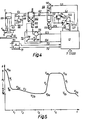
- FIG. 4 shows the hydraulic system 13, with which the feed movement of the grinding tool 5 and its lifting and infeed movement taking place at certain times are accomplished.
- the 4/3-way valve 55 is connected via line 52 to the pump 56, which the pressure medium required for the hydraulic system, for. B. oil, supplies and can deliver different flow rates according to the feed conditions. Depending on the preselection of 55, the feed rate and the delivery rate of the pump are in a fixed ratio.
- the return line 53 the valve 55 is connected to the reservoir 57, from which the pump 56 draws its oil.
- the valve 55 contains the two electromagnets 58, 59, which are actuated by the NC control 12 via lines 121, 125. A symbol for the valve springs (return springs) is drawn at both ends of the valve 55.
- Behind the 4/3-way valve 55 is a proportional valve 60, which is arranged close to the working cylinder 1 of the form grinding machine. Great importance is attached to short connecting lines 63, 64 to working cylinder 1.
- the tool 5 which is known to be attached to the plunger plate 4 of the sleeve 3, should be moved in the direction of the workpiece 9 and the work table 10. It is the feed movement and the fast infeed movement. Magnet 58 is selected at valve 55 for the downward feed; The rapid delivery is controlled without preselection at valve 55 only with signal 123 and release 124 is secured. The other movements will be discussed later.
- the NC control 12 actuates the electromagnet 58, so that the valve 55 connects the line 52 from the pump 56 to the line 61 to the proportional valve 60 and the return line 62 from the proportional valve to the pressure line 61.
- the NC control 12 influences the electromagnet 65 of the proportional valve 60 via line 123, comparator 76, amplifier 77, switch 78 of the proportional controller 75 so that the pressure lines 61, 64 are connected to one another.
- the print medium e.g. ⁇ I
- the oil flows from the lower space of the working cylinder 1 via the return lines 63, 62.
- the piston area of the lower space is significantly smaller than that of the upper space. This is for the reason that the feed pump 56 has to deliver a smaller amount of oil.
- valve 55 the back-flowing oil is reintroduced into the pressure line 61.
- the return line 63 there is a check valve 67 which blocks the oil flow from the lower space of the working cylinder 1.
- the oil can only flow via the throttle 66, which builds up such a high pressure that the plunger 3 and the piston 111 move the tool 5 to the workpiece 9 at a very low speed. If this speed is to be increased, this is done via valve 68, which opens after a certain pressure is exceeded and thereby forms a bypass to the throttle 66.
- FIG. 4 shows two boxes 70, 71 near the tool 5 and work table 10 with workpiece 9. They are intended to symbolically represent measuring devices.
- the measuring device 70 is intended to be a dynamometer which measures the contact force F between the tool 5 and the workpiece 9 and outputs a voltage signal U (analog or digital) via line 73 into the NC controller 12.
- the measuring device 71 is intended to be a distance meter that measures the distance Z that the tool 5 travels in the Z coordinate.
- the odometer 71 generates electrical impulses which are given to the NC control 12 via line 72. These impulses contain information about the direction of the movements and the current position of the tool.
- the path Z can e.g. B. can be detected by the measuring device 1 of Figure 1.
- the two measuring devices 70, 71 have their sensors arranged at the most convenient locations for them.
- the proportional controller 75 shown in FIG. 4 contains a comparator 76 which compares the SET value signals for the feed rate (NC control 12, line 123) with the ACTUAL value signals of the measuring element 69.
- the measuring member 69 detects the actual position of the control slide in the proportional valve 60. If there is a difference between the two electrical signals, the comparator 76 generates an electrical difference signal which is given via the amplifier 77 with an adjustable gain, switch 78 to the electromagnet 65 and the control slide in the proportional valve 60 moves until the desired valve position, which is programmed in the NC control 12, is set.
- the proportional controller 75 makes the control slide of the valve 60 insensitive to static and dynamic disturbing forces, so that the movement between tool 5 and workpiece 9 is controlled very precisely according to the values programmed in the NC control 12.
- the NC controller 12 also processes the ACTUAL value signals from the measuring devices 70, 71.
- the adjustment takes place at every moment of the feed movement, the intermittent feed retraction movement and during the dynamically controlled transitions between the individual movement types.
- the adaptation takes place if the surfaces in engagement between tool 5 and workpiece 9 become larger during the grinding process.
- the adaptation processes are described in more detail later in connection with FIGS. 6, 7, 8.
- the proportional controller 75 is only in operation if a so-called “enable” signal is additionally present on the line 124.
- FIG. 4 shows a second proportional valve 54 between the pressure line 52 of the pump 56 and the return flow line 53 to the reservoir 57, which is electrically controlled by the NC control 12 via line 122.
- the maximum pressure for the entire hydraulic system can be changed.
- the pressure is reduced by reducing the spring preload 54, so that part of the oil flows from the pressure line 52 into the return line 53.
- a height The pressure of the pump 56 is achieved by increasing the spring preload via the magnet on the valve 54.
- the NC control 12 determines the amount of the pressure change via line 122.
- the NC controller 12 is supplied via the data bus 120 with the program for the grinding work, including the various types of movement between the tool 5 and the workpiece 9. If, for example, the predetermined grinding path Z 2 (FIG.
- the pressure is increased in a certain manner so that the grinding process is accelerated.
- the acceleration is set taking into account the vulnerability of the materials of tool 5 and workpiece 9.
- the pressure is reduced by the proportional valve 54 when the tool 5 has covered the predetermined grinding path Z 2 faster than in the predetermined time t 2 .
- the 4/3-way valve 55 is activated via line 125.
- the electromagnet 59 moves the control slide in the valve 55 so that the pressure line 52 of the feed pump 56 is connected to the line 62.
- the line 61 is connected to the return line 53, which leads to the reservoir 57.
- the proportional controller 75 and the proportional valve 60 are controlled via line 123.
- the electromagnet 65 moves the control slide in the valve 60 so that the feed pump 56 pumps oil via pressure lines 52, 62, 63, valve 67, which is not a check valve in the flow direction, oil into the lower space of the cylinder 1.
- the oil reaches the reservoir 57 via lines 64, 61, 53 from the upper space of the cylinder 1.
- the tool 5 now moves away from the workpiece 9 at a low speed.
- interval movements must also be carried out at a much higher speed, which in certain times, e.g. can be between 1 second and 120 seconds.
- These interval movements consist of a quick lifting of the tool 5 from the workpiece 9 and a rapid delivery of the tool 5 to the workpiece 9.
- the rapid lifting and infeed movement must not occur suddenly, since otherwise parts of the surface of the Workpiece 9 can be damaged.
- This disadvantage of the known systems can be explained by the fact that e.g. with a rapid lifting movement of the tool 5 from the workpiece 9, a vacuum is formed in the gap, since the washing liquid cannot flow in from the washing unit 14 quickly enough.
- Such a vacuum means that the piston 111 and plunger 3 in the working cylinder 1 have to be moved upwards with great force, which causes damage to the surfaces.
- such sudden changes in the movements produce dynamic disturbances such as. B. strong blows and shocks throughout the system. This can impair the high precision of the adjusted construction parts.
- the tool 5 is moved to the workpiece 9 at high speed and suddenly stops.
- suddenly a high pressure builds up, since the rinsing liquid is compressed very quickly in the narrowing gap and the rinsing unit 14 is not able to initiate countermeasures such as e.g. B. faster suction and reduction in the amount of rinsing liquid. In this case, too, there are strong impacts and impacts in the system.
- the invention avoids the disadvantages of the undesirable impacts and impacts mentioned. Shocks and bumps are avoided by the embodiment of Figure 4.
- the disadvantageous, sudden pressure changes in the washing liquid are eliminated by a compensating vessel 170 which, according to FIG. 9, is arranged in the liquid line 171 between the washing unit 14 and the tool 5 or workpiece 9.
- the flushing liquid is under pressure in line 171, which is generated by the feed pump in the flushing unit 14.
- the expansion tank 170 is divided in the middle by an elastic membrane 172 into the two spaces 173, 174.
- the upper room 173 contains air and is sealed. The rinsing liquid enters the lower space 174.
- the rinsing liquid escapes into the lower space 174 of the compensating vessel 170. This avoids the sudden increase in pressure in the grinding gap 46. If a pressure reduction is formed in the grinding gap 46 (tool 5 moves away from the workpiece 9), then sufficient rinsing liquid flows from the pressurized space 174 into the grinding gap 46, in addition to the rinsing liquid conveyed by the pump in the unit 14. The air pressure in the upper room 173 supports this process.
- the expansion tank 170 of FIG. 9 also works without the membrane 172.
- the NC controller 12 starts these fast interval movements via the lines 121, 122, 123, 125.
- the valves 54, 55, 60 control these fast movements.
- the proportional valve 60 is designed so that, in cooperation with the NC controller 12, the transitions between the interval movements (high speed) and the feed and retraction movements (low speed) are smooth will.
- the hydraulic system is therefore able to reduce the very large differences in speed changes to a reasonable degree. This increases the working accuracy of the machine.
- the movement sequence of the tool 5 will now be explained in more detail with reference to FIG. 5, taking into account the hydraulic system according to the invention from FIG.
- the time t is plotted on the abscissa of FIG. 5 and the path Z on the ordinate. It is now assumed that the tool 5 is moved towards the workpiece 9 at high speed V 1 .
- the path that the tool 5 travels to the workpiece 9 is denoted by Z.
- the first part V 1a of the speed is the controlled transition (acceleration) from the speed «zero» to the high infeed speed V ,. If the tool 5 is located just in front of the workpiece 9, the controlled transition (braking) from the high infeed speed V to the speed “zero” takes place. This part is labeled V lb.
- the path Z 3 covered here is the same length as the infeed path Z 1 ', but is shifted downwards by the grinding path Z 2 .
- the transitions V 3a (accelerating) and V 3b (braking) are also present here.
- the cycle shown in FIG. 5 lasts between 1 and 60 seconds.
- the system of Figure 4 ensures that the speeds V 1 , V 2 , V 3 and their transitions V 1a , V 1b ' V 2a , V 2b' V 3a , V 3b are adapted to the current conditions in the grinding gap.
- the times t 1 , t 2 , t 3 , t 4 can e.g. B. be changed so that the rest times are omitted and the grinding time t 2 is extended.
- the grinding time t 2 can also be shortened.
- the duration of a cycle can also be made longer than 60 seconds. So one cycle follows the other until the grinding work is finished.
- one or more cycles V 3 , V can be repeated without a feed movement V 2 when the prescribed machining depth in the workpiece 9 has been reached (ie at the time of finishing the grinding work) will.
- the number of these so-called “regrinding” cycles can either be permanently programmed or made dependent on a minimum value of the contact pressure in the grinding gap. This is accomplished by the NC controller 12.
- the advantage of these cycles is that the accuracy of the ground spatial dimensions of the workpiece 9 is increased on all sides.
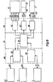
- FIG. 6 shows the individual components of the NC control 12, which are divided into input, central, output and peripheral units.
- the components as such are known, so that their operation is only described to the extent necessary for understanding the invention.
- the input unit 80 contains the operation interface 83 and the machine interface 84.
- the program input with memory 85 and the control panel 7 are connected to the operation interface 83 via the data bus 120.
- the data flow in the data bus 120 goes in both directions, which is indicated by the arrows.
- the complete program for the entire grinding process of the workpiece 9 is stored in the program input 85 (for example on magnetic memory), and / or the program can optionally be operated in the control panel 7 by the operator can be entered or changed.
- the operator stores the entered or changed data in one of the memories of the program input 85.
- the working cylinder 1 is connected to the machine interface 84 via the lines 72, 73 (FIGS. 4, 6, 7).
- the data belonging to the program are shown in FIGS. 7, 8.
- the two interfaces 83, 84 transfer the data to the central processing unit 90, in which they are processed taking into account the specified technology rules and are given as results in the output unit 82.
- the arrows of the connecting lines indicate the data flow, and in the output unit 82 there are as many interfaces 86, 87, 88 as there are peripheral actuating units 13, 11, 14, 56 necessary to control the entire grinding process of the workpiece 9.
- the hydraulic system 13 is connected via lines 121, 122, 123, 124, 125 to interface 86 for controlling valves 54, 55, 60 and controller 75 (FIG. 4).
- the hydraulic and flushing interface 87 is connected via lines 126, 127 to the feed pump 56 of the hydraulic system 13 and to the feed pump of the flushing and filter unit 14.
- the drive motor which drives the eccentric drives 11 in the planetary movement (FIGS. 1, 2) via the drives 20, 21, is controlled by the machine interface 88 via the line 128.
- the adjusting motor which adjusts the eccentricity of the eccentric drives 11 (FIGS. 1, 2) via the adjusting drives 37, 45, is controlled by the machine interface 88 via the line 129.
- the same machine interface 88 of FIG. 6 controls the electromagnet of the lifting cylinder 34 via the line 130, the clutch 31 in the driver 32 a short time before the eccentricity is adjusted coupled in and decoupled again after the set eccentricity (FIG. 2).
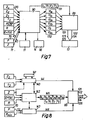
- FIG. 7 shows the input data which are necessary for carrying out the entire grinding process on the workpiece 9 and which are either stored in the program input 85 or are entered by the operator via the control panel 7.
- the limits of the entire movement of the tool 5 in the Z coordinate are determined.
- the values Zu for the upper limit and Z d for the lower limit (depth gauge 2) are entered.
- the value Z 2 indicates the path in mm that the tool 5 is to travel in the Z coordinate during a cycle within a cycle.
- the value t 2 indicates the time in seconds that must not be exceeded for grinding at the predetermined speed V 2 (see also FIG. 5).
- the amount P min is the lower limit in Kp / mm 2 , which the contact pressure between tool 5 and workpiece 9 should not fall below.
- this amount P min is intended as the lower limit for the planetary idling movements of the workpiece 9, which are carried out at the end of the entire grinding process without feed in the Z coordinate to increase the accuracy of the image of the workpiece 9 until the value P min is reached .
- the amount P max is the upper limit, which the pressure between tool 5 and workpiece 9 must not exceed, since otherwise their surfaces can be damaged.
- the amount R is used to enter the number of cycles or interval movements (FIG. 5; lifting V 3 , delivering V 1 ) for the entire grinding process.
- E f (Z) is used to enter the eccentricity as a function of the depth of penetration of the tool 5 and the workpiece 9 (Z coordinate).
- the amount of eccentricity E can be determined with which the planetary movement of the workpiece 9 is carried out in the X and Y coordinates should. Every amount of the penetration depth Z has a certain value of the eccentricity E.
- This dependence between Z and E can be represented in a graph as any curve. This dependency can preferably be represented as a straight line or as a circular arc.
- the technological values mentioned so far are transported via data bus 120 to central processing unit 90 and processed there.
- the measuring device 70 which has its sensor on or in the grinding gap 46 or in the feed line 171 of the rinsing liquid from the rinsing unit 14 to the rinsing channels in the workpiece 9, gives the electrical signals at any moment which indicate the actual pressure P between the tool 5 and the workpiece 9 specify, via line 73 to the central processing unit 90.
- the measuring device 71 the sensor z. B. is provided on the depth gauge 2 ( Figure 1), gives its information about the IST position of the tool 5 in the Z coordinate as electrical pulses by means of line 72 in the central processing unit 90th
- the feed pump in the flushing and filter unit 14 can also be controlled via line 127, so that the pressure of the flushing medium is adjusted within certain limits to the conditions in the grinding gap 46 between tool 5 and workpiece 9. This applies to the actual grinding process in the Z, coordinate and especially to the interval lifting and infeed movement (V 3 , V 1 ).
- the central processing unit 90 outputs the speeds V "V 2 , V 3 , which are adapted to the conditions in the grinding gap 46, and the dynamically controlled transitions V 1a ... V 3b into the advance selector 89 via the data bus 131. From there the individual information in a specific sequence via lines 121, 122, 123, 124, 125 to valves 54, 55, 60 and to controller 75 of hydraulic system 13.
- FIG. 8 shows the control of the hydraulic system 13 for each cycle.
- the two comparators 140, 143 and the processor 142 are components of the central processing unit 90 in FIGS. 6 and 7.
- the program input 85 or 7 is carried out approximately with the same values as in FIG. Z 2 and t 2 are the grinding path and the grinding time which the tool 5 may require in each cycle. These values are given in the comparator 140, which works with a clock 141 as a standard measure.
- the grinding path Z for all cycles serves as a basis for comparison and is fed into the comparator 140 and into the processor 142.
- the processor is connected to the comparator and monitors that the grinding process is ended in each cycle if the grinding path Z 2 has been reached before the grinding time t2 or vice versa.
- a termination signal is generated which reaches the advance selector 89 via the line 144.
- the values of Z 2 and t z can be different for each cycle. This depends on the type of spatial shape to be produced and on the material of the workpiece 9.
- the workpiece can, for example, be composed of several different materials.
- the processor 142 is entered the number R of the intended cycles. Furthermore, the processor receives the input of the eccentricity E as a function of the total grinding path Z. This has already been described in FIG. 7.
- the eccentric drives 11 are controlled in the same way as in the case of Embodiment of Figure 7. In each cycle, the eccentricity E of the planetary movement of the workpiece 9 can be different.
- the amount P m is the lower pressure limit in the grinding gap 46, which must not be undercut.
- the measuring device 70 supplies the actual value of the pressure between the tool 5 and the workpiece 9 to the comparator 143 via line 72, which compares it with P min .
- the processor 142 is in permanent communication with the comparator and, by changing the control signals on the data bus 145, ensures that the lower pressure limit P min is not reached. Should this nevertheless happen, a signal "No feed” is sent via line 146 to the Advance Selector 89. The program of the current cycle is run through again. In most cases, the conditions in the grinding gap have improved so that the machining of the workpiece 9 can continue.
- the central processing unit 90 in FIGS. 6 and 7 reacts in such a way that these movements are continued without feed up to the lower pressure limit P min and then switched off.
- the processor 142 of FIG. 8 outputs the manipulated variables for the speeds V1, V 2 , V 3 , the transitions V 1a ... V 3b and for the times t " (t" t 2 , t 3 %) via data bus 145 on the advance selector 89, which controls the valves 54, 55, 60 and the controller 75 in the hydraulic system 13 in a certain sequence via the lines 121, 122, 123, 124, 125.
- the contact pressure between the tool 5 and the workpiece 9 and the speeds of the various movements are adapted to the conditions in the grinding gap 46.
- FIGS. 1-9 Preferred exemplary embodiments of the invention have been described in FIGS. 1-9. These exemplary embodiments can be modified in individual parts, the actual inventive idea not being changed.
- the hydraulic system 13 of Figures 1 and 4 which performs the feed movement at low speed during grinding, the intermittent feed and lift movement at high speed and the transitions between the movements, are replaced by an electrical circuit.
- FIG. 1 shows only one pair of tools 5 and workpiece 9. Of course, several such pairs can be provided, all of which are machined in one operation. It should be noted that each pair (tool 5 and workpiece 9) is clamped on the plate 4 and table 10 offset from the other pair. These measures prevent inaccuracies in machining, which arise due to the elasticity of the machine parts 1, 3, 4, 8, 10 influenced by the dynamic machining forces. This problem arises not only when one side of the workpiece 9 is ground more than the other side, but also when machining is the same on all sides.
Landscapes
- Engineering & Computer Science (AREA)
- Mechanical Engineering (AREA)
- Chemical & Material Sciences (AREA)
- Chemical Kinetics & Catalysis (AREA)
- Electrochemistry (AREA)
- Grinding And Polishing Of Tertiary Curved Surfaces And Surfaces With Complex Shapes (AREA)
- Electrical Discharge Machining, Electrochemical Machining, And Combined Machining (AREA)
Claims (23)
Applications Claiming Priority (4)
| Application Number | Priority Date | Filing Date | Title |
|---|---|---|---|
| CH743282 | 1982-12-21 | ||
| CH7432/82 | 1982-12-21 | ||
| CH560883A CH663745A5 (de) | 1983-10-14 | 1983-10-14 | Maschine zur herstellung eines werkstueckes einer bestimmten raumform mittels eines formenschleif-werkzeuges. |
| CH5608/83 | 1983-10-14 |
Publications (3)
| Publication Number | Publication Date |
|---|---|
| EP0118606A2 EP0118606A2 (fr) | 1984-09-19 |
| EP0118606A3 EP0118606A3 (en) | 1985-12-27 |
| EP0118606B1 true EP0118606B1 (fr) | 1989-04-12 |
Family
ID=25698072
Family Applications (1)
| Application Number | Title | Priority Date | Filing Date |
|---|---|---|---|
| EP83112067A Expired EP0118606B1 (fr) | 1982-12-21 | 1983-12-01 | Machine pour fabriquer une électrode d'une forme définie au moyen d'un outil profilé de rodage |
Country Status (3)
| Country | Link |
|---|---|
| US (1) | US4557075A (fr) |
| EP (1) | EP0118606B1 (fr) |
| DE (1) | DE3379579D1 (fr) |
Families Citing this family (9)
| Publication number | Priority date | Publication date | Assignee | Title |
|---|---|---|---|---|
| CH661890A5 (de) * | 1983-10-01 | 1987-08-31 | Werner Ullmann | Antrieb fuer eine maschine zur herstellung eines werkstueckes einer bestimmten raumform mittels eines formenschleif-werkzeuges. |
| US4768308A (en) * | 1986-12-17 | 1988-09-06 | University Of Rochester | Universal lens polishing tool, polishing apparatus and method of polishing |
| WO1990008626A1 (fr) * | 1989-02-03 | 1990-08-09 | Extrude Hone Corporation | Procede et outils d'abrasion pour meulage orbital |
| US5081794A (en) * | 1990-08-17 | 1992-01-21 | Haney Donald E | Sander with orbiting platen and abrasive |
| US5181342A (en) * | 1990-08-17 | 1993-01-26 | Haney Donald E | Sander with orbiting platen and abrasive |
| US20080197010A1 (en) * | 2007-02-21 | 2008-08-21 | Chih Lin | Apparatus and method for air relief in an air switch |
| JP5484551B1 (ja) * | 2012-11-20 | 2014-05-07 | 株式会社キョクトー | 電極チップの研磨方法 |
| CN113001366B (zh) * | 2021-03-01 | 2023-05-09 | 天津派浦澜能源科技有限公司 | 一种输送管道表面用除锈装置 |
| CN115519442B (zh) * | 2022-09-27 | 2024-10-08 | 青岛威特锐智能装备有限公司 | 研磨机 |
Family Cites Families (11)
| Publication number | Priority date | Publication date | Assignee | Title |
|---|---|---|---|---|
| US2921487A (en) * | 1956-08-27 | 1960-01-19 | Schabot Bernard William | Indexing fixture |
| US3443341A (en) * | 1963-08-30 | 1969-05-13 | Honda Motor Co Ltd | Gear grinding machine |
| US3698138A (en) * | 1969-08-13 | 1972-10-17 | Toyoda Machine Works Ltd | Grinding machine with adaptive control system |
| US4156327A (en) * | 1972-05-16 | 1979-05-29 | Easco-Sparcatron, Inc. | Method for total form machining of metal |
| GB1407726A (en) * | 1973-03-28 | 1975-09-24 | Grafton Corp | Apparatus for use in forming electrodes |
| US3988863A (en) * | 1973-09-14 | 1976-11-02 | Oconnor Thomas John | Structure for and method of total form abrasion machining |
| CA1037292A (fr) * | 1975-02-04 | 1978-08-29 | Triangle Tool Company | Appareil pour l'obtention d'un mouvement orbital relatif lors de l'usinage par decharge electrique |
| DE2711697C2 (de) * | 1977-03-17 | 1983-11-17 | Friedrich Deckel AG, 8000 München | Einrichtung zur Vorschub- und Rückzugsteuerung der Elektrode einer Elektroerosionsmaschine |
| US4186529A (en) * | 1977-06-28 | 1980-02-05 | S. E. Huffman Corporation | Programmably controlled method for grinding end cutting tools and the like |
| US4186527A (en) * | 1978-08-07 | 1980-02-05 | Hausermann Abrading Process Company | Apparatus for shaping electrodes |
| US4277915A (en) * | 1979-07-06 | 1981-07-14 | Hausermann Abrading & Process Co. | Apparatus for shaping electrodes |
-
1983
- 1983-12-01 EP EP83112067A patent/EP0118606B1/fr not_active Expired
- 1983-12-01 DE DE8383112067T patent/DE3379579D1/de not_active Expired
- 1983-12-16 US US06/562,108 patent/US4557075A/en not_active Expired - Fee Related
Also Published As
| Publication number | Publication date |
|---|---|
| EP0118606A2 (fr) | 1984-09-19 |
| EP0118606A3 (en) | 1985-12-27 |
| US4557075A (en) | 1985-12-10 |
| DE3379579D1 (en) | 1989-05-18 |
Similar Documents
| Publication | Publication Date | Title |
|---|---|---|
| DE3433363C1 (de) | Antriebsvorrichtung zum spielfreien umwandeln einer drehbewegung in eine linearbewegung | |
| DE2824266C2 (de) | Kopiereinrichtung zum Entgraten von Werkstücken | |
| DE69421859T2 (de) | Schleifmaschine | |
| DE102006015711B3 (de) | Stanzeinrichtung | |
| EP0118606B1 (fr) | Machine pour fabriquer une électrode d'une forme définie au moyen d'un outil profilé de rodage | |
| DE2731084C3 (de) | Stößelverstellung für schnellaufende Schnittpressen | |
| DE3024433A1 (de) | Vorrichtung zur spanabhebenden bearbeitung von nocken | |
| EP3501730A1 (fr) | Machine à fraiser dentaire ainsi que procédé | |
| EP0045380A2 (fr) | Circuit de commande pour un dispositif de réglage et de dressage d'une meule | |
| DE19536036C2 (de) | Schrittvorschub-Bearbeitungssystem | |
| CH658617A5 (de) | Zahnflankenschleifmaschine mit doppelkegelfoermiger schleifscheibe. | |
| DE3200979A1 (de) | Elektrodenvorschubsystem fuer elektrische bearbeitung | |
| DE2818667A1 (de) | Werkzeugmaschine zum raeumlichen polieren mit magnetschleifpulver im magnetfeld von werkstuecken, die die form eines rotationskoerpers besitzen | |
| CH663745A5 (de) | Maschine zur herstellung eines werkstueckes einer bestimmten raumform mittels eines formenschleif-werkzeuges. | |
| DE9005834U1 (de) | Manipulator fuer schmiedemaschinen, insbesondere mehr-stoessel-schmiedemaschinen | |
| CH631913A5 (de) | Einrichtung zum steuern der zustellung einer schleifscheibe relativ zu einer abrichtvorrichtung. | |
| DE10107484B4 (de) | Hublagenregelung der Stößel von Stanzpressen | |
| DE3703848C2 (fr) | ||
| DE2645426C2 (de) | Einrichtung zur maßgesteuerten Bearbeitung von Werkstücken auf Honmaschinen | |
| DE2335575B2 (fr) | ||
| EP0165249B1 (fr) | Entrainement pour le moulage en moule | |
| EP0292642B1 (fr) | Procédé et dispositif de commande d'un mécanisme de génération d'une machine à rectifier des roues dentées | |
| DE2919829A1 (de) | Automatische poliereinrichtung | |
| EP0131134B1 (fr) | Procédé et machine de mise en forme pour le traitement érosif à étincelles de pièces d'usinage | |
| DE3441305C2 (fr) |
Legal Events
| Date | Code | Title | Description |
|---|---|---|---|
| PUAI | Public reference made under article 153(3) epc to a published international application that has entered the european phase |
Free format text: ORIGINAL CODE: 0009012 |
|
| AK | Designated contracting states |
Designated state(s): DE FR GB IT |
|
| 17P | Request for examination filed |
Effective date: 19850116 |
|
| RAP1 | Party data changed (applicant data changed or rights of an application transferred) |
Owner name: ULLMANN, WERNER, DR. |
|
| PUAL | Search report despatched |
Free format text: ORIGINAL CODE: 0009013 |
|
| AK | Designated contracting states |
Designated state(s): DE FR GB IT |
|
| 17Q | First examination report despatched |
Effective date: 19860730 |
|
| GRAA | (expected) grant |
Free format text: ORIGINAL CODE: 0009210 |
|
| AK | Designated contracting states |
Kind code of ref document: B1 Designated state(s): DE FR GB IT |
|
| PG25 | Lapsed in a contracting state [announced via postgrant information from national office to epo] |
Ref country code: IT Free format text: LAPSE BECAUSE OF FAILURE TO SUBMIT A TRANSLATION OF THE DESCRIPTION OR TO PAY THE FEE WITHIN THE PRESCRIBED TIME-LIMIT;WARNING: LAPSES OF ITALIAN PATENTS WITH EFFECTIVE DATE BEFORE 2007 MAY HAVE OCCURRED AT ANY TIME BEFORE 2007. THE CORRECT EFFECTIVE DATE MAY BE DIFFERENT FROM THE ONE RECORDED. Effective date: 19890412 Ref country code: GB Effective date: 19890412 |
|
| REF | Corresponds to: |
Ref document number: 3379579 Country of ref document: DE Date of ref document: 19890518 |
|
| EN | Fr: translation not filed | ||
| GBV | Gb: ep patent (uk) treated as always having been void in accordance with gb section 77(7)/1977 [no translation filed] | ||
| PGFP | Annual fee paid to national office [announced via postgrant information from national office to epo] |
Ref country code: FR Payment date: 19891214 Year of fee payment: 7 |
|
| PLBE | No opposition filed within time limit |
Free format text: ORIGINAL CODE: 0009261 |
|
| STAA | Information on the status of an ep patent application or granted ep patent |
Free format text: STATUS: NO OPPOSITION FILED WITHIN TIME LIMIT |
|
| 26N | No opposition filed | ||
| PGFP | Annual fee paid to national office [announced via postgrant information from national office to epo] |
Ref country code: DE Payment date: 19950511 Year of fee payment: 12 |
|
| PG25 | Lapsed in a contracting state [announced via postgrant information from national office to epo] |
Ref country code: DE Effective date: 19960903 |
|
| PG25 | Lapsed in a contracting state [announced via postgrant information from national office to epo] |
Ref country code: FR Free format text: LAPSE BECAUSE OF NON-PAYMENT OF DUE FEES Effective date: 19901231 |