EP0118636A2 - Optische Plattenkassette - Google Patents
Optische Plattenkassette Download PDFInfo
- Publication number
- EP0118636A2 EP0118636A2 EP83305560A EP83305560A EP0118636A2 EP 0118636 A2 EP0118636 A2 EP 0118636A2 EP 83305560 A EP83305560 A EP 83305560A EP 83305560 A EP83305560 A EP 83305560A EP 0118636 A2 EP0118636 A2 EP 0118636A2
- Authority
- EP
- European Patent Office
- Prior art keywords
- frame
- sald
- sleeve
- drive
- optical disc
- Prior art date
- Legal status (The legal status is an assumption and is not a legal conclusion. Google has not performed a legal analysis and makes no representation as to the accuracy of the status listed.)
- Withdrawn
Links
- 230000003287 optical effect Effects 0.000 title claims abstract description 32
- 230000007246 mechanism Effects 0.000 description 24
- 238000003780 insertion Methods 0.000 description 12
- 230000037431 insertion Effects 0.000 description 12
- 239000000758 substrate Substances 0.000 description 5
- 238000006073 displacement reaction Methods 0.000 description 3
- 239000011232 storage material Substances 0.000 description 3
- 229910000975 Carbon steel Inorganic materials 0.000 description 1
- 239000010962 carbon steel Substances 0.000 description 1
- 239000000356 contaminant Substances 0.000 description 1
- 238000011109 contamination Methods 0.000 description 1
- 238000013500 data storage Methods 0.000 description 1
- 239000000428 dust Substances 0.000 description 1
- 239000007769 metal material Substances 0.000 description 1
- 238000000034 method Methods 0.000 description 1
- 229910052714 tellurium Inorganic materials 0.000 description 1
- PORWMNRCUJJQNO-UHFFFAOYSA-N tellurium atom Chemical compound [Te] PORWMNRCUJJQNO-UHFFFAOYSA-N 0.000 description 1
- 230000032258 transport Effects 0.000 description 1
Images




Classifications
-
- G—PHYSICS
- G11—INFORMATION STORAGE
- G11B—INFORMATION STORAGE BASED ON RELATIVE MOVEMENT BETWEEN RECORD CARRIER AND TRANSDUCER
- G11B17/00—Guiding record carriers not specifically of filamentary or web form, or of supports therefor
- G11B17/02—Details
- G11B17/04—Feeding or guiding single record carrier to or from transducer unit
- G11B17/041—Feeding or guiding single record carrier to or from transducer unit specially adapted for discs contained within cartridges
- G11B17/049—Insertion of discs having to be extracted from the cartridge prior to recording or reproducing
-
- G—PHYSICS
- G11—INFORMATION STORAGE
- G11B—INFORMATION STORAGE BASED ON RELATIVE MOVEMENT BETWEEN RECORD CARRIER AND TRANSDUCER
- G11B23/00—Record carriers not specific to the method of recording or reproducing; Accessories, e.g. containers, specially adapted for co-operation with the recording or reproducing apparatus ; Intermediate mediums; Apparatus or processes specially adapted for their manufacture
- G11B23/02—Containers; Storing means both adapted to cooperate with the recording or reproducing means
- G11B23/03—Containers for flat record carriers
- G11B23/0328—Containers for flat record carriers the disc having to be extracted from the cartridge for recording reproducing, e.g. cooperating with an extractable tray
Definitions
- Capacitive storage discs are provided protection during storage, loading and unloading by a cartridge assembly including a sleeve into which a framed optical disc is inserted and latched. Upon insertion of the cartridge into its drive, the frame automatically unlatches from the sleeve, such that the framed optical disc remained in the drive upon removal of the sleeve.
- an optic disc drive system in which the empty sleeve component of an optical disc cartridge is utilized to lock the optical disc in its operational position while occupying a storage location within the drive system.
- the locking/storage feature is achieved by providing adjacent to the conventional disc insertion opening in the drive frame an additional opening for receipt of the empty sleeve component and by providing guides within the drive for positioning the empty sleeve over the optical disc.
- the empty sleeve cooperates with a spring loaded frame/disc lowering mechanism which lowers the optical disc to the drive spindle where it is held by a magnetic force generated by a magnitized portion of the spindle.
- the sleeve also cooperates with a frame/sleeve latching mechanism to facilitate withdrawal of a frame supported optical disc from the sleeve and reinsertion of the frame supported optical disc back into the sleeve.
- a plurality of spring loaded members support the frame member before the sleeve actuates the lowering mechanism and free the optical disc from the spindle upon withdrawal of the sleeve from its locking/storage position.
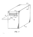
- FIG. 1 there is shown in perspective view the exterior of an optical disk drive system 2.
- the front panel 4 of drive system 2 has therein first and second, closely spaced, tandemly disposed slotted openings 6 and 8, respectively.
- Each of the openings 6 and 8 is sized in height and width to accept close tolerance insertion of the sleeve component 2 of an optical disk cartridge 10 (shown in phantom in Figure 1).
- the optical disk cartridge 10 would include the rigid, hollowed sleeve component 12 having an open end 14, a substantially rigid frame member 16 having a central, circular opening 18, and a rigid optical disk 20 of a diameter slightly less than the diameter of opening 18 in frame member 16.
- Disk 20 includes an annular plastic substrate 26 having an outer circular edge 27 and an inner circular opening 28. Embedded within the inner portion of substrate 26 and encircling the opening 28 is an annulas of metallic material 21, such as, for example, carbon steel. A conventional optical data storage material of, for example, tellurium, is coated over a planar surface of the substrate 26 from proximate its opening 28 to proximate its outer edge 27 whereby a ring 23 free of storage material is provided at the extreme outer edge of the substrate 26.
- the cartridge is symmetrical and may be used with a substrate 26 that is coated with storage material on one or both sides.
- disk 20 is first loosely fitted between two pairs of frame tabs 32 that extend slightly into opening 18 along the top and bottom planar surfaces of frame 16 and then seated on a pair of frame tabs 30 that extend slightly into opening 18 along the bottom planar surface of frame 16. Once so placed and seated, the disk 20 is trapped in opening 18 by a pair of snap-in tabs 34 secured adjacent tabs 30 along the top planar surface of frame 16. After the optical disk is trapped, the frame/disk assembly is inserted into the cavity of the sleeve 12 via opening 14.
- the cavity of sleeve 12 is sized to provide a fairly tight fit between the sleeve 12 and the frame/disk assembly, and the frame is provided with a shoulder 36 to limit the extent of movement of the frame/disk assembly into the cavity of sleeve 14.
- Two pairs of adjacently disposed tabs 40 project from the interior major surfaces of sleeve 12 into the cavity of sleeve 12 near its closed end.
- tabs 40 which have a vertical spacing equal to the thickness of disk 20, act in conjunction with a pair of similarly separated tabs provided by one snap-in clip 42 located near the shoulder end of the frame 16 to grab disc 20 along ring 23 thereof whereby the disc 20 is lifted free of tabs 30-32 when the frame/disk is inserted into the sleeve 12 such that the disk is out of contact with tabs 30-32 when the cartridge is in storage.
- portions of the frame 16 are cut out to provide a pair of arms 44 which are flexible in a direction transverse to their length.
- Each arm 44 has a ramped portion 46 at its extremity and a nib portion 48 that faces outwardly and slightly beyond a major edge of frame 16.
- Frame 16 also has a pair of protrusions 50, one at the open end of each of the cut-out portions.
- recesses 52 are provided in the side walls 13 of sleeve 12 at locations adjacent to the positions of nibs 48 when the frame 16 is at the maximum insertion position within sleeve 12. Accordingly, when the frame/disk assembly is fully inserted into sleeve 12, the nibs 48 and the recesses 52 mate to immoveably lock the frame/disk assembly to the sleeve 12.
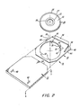
- a flat, U-shaped plate or functionally equivalent mounting surface 60 extends rearward from front panel 4.
- Plate 60 with its closed end adjacent panel 4, is supported from below in a conventional manner (not shown).
- Plate 60 has multiple trios of slots 61 which receive the legs 62 of a plurality of disk supports 63 (only two shown).
- Plate 60 also supports rigid vertically disposed side plates 65 and 66 each including a pair of horizontal ledges 67 and 68, as shown in Figures 4 and 4a.
- Ledges 67 and 68 have slots 167 and 168, respectively, which define first and second guiding mechanisms 69, 70, respectively.
- the slotted opening 6 lies substantially within the plane of the slots 167
- the slotted opening 8 lies substantially within the plane of the slots 168, whereby the guiding mechanisms 69, 70 guide the movement of sleeve 12 when it is inserted into the drive as described hereinafter.
- Each lowering mechanism is comprised of a pair of members 73 each having a wedge shaped section 73' and an arm section 73" with a rotation axis provided along a hole 74 in the arm section. Holes 74 receive shoulder screws 76 for fastening members 73 to the side walls. Springs 77, each held in part by its associated screw 76, provide an upward force to each member 73 whereby the sections 73' of members 73 are normally above the plane of slots 168. Also supported, by side wall 66 is a front door interlock member 800 having arm sections 801 and 802.
- slots 6 and 8 are actually defined by an elongated member 100 that fits between front panel members 101 and 102:
- a drive spindle 400 supported from below in a conventional manner (not shown), extends upward through the opening in U-shape plate 60.
- Spindle 400 includes a raised conical frustrum section 401, having a diameter substantially mated to the diameter of the opening 28 of disk 20, and a supporting section 402.
- a magnet 403 forms an integral part of the upper surface of support section 402.
- the cartridge 10 is inserted into the lower slotted opening 6 and once inside the drive is guided to the rear by guiding mechanisms 69 ( Figure 6). Just prior to full insertion of the cartridge within the drive 2, the ramped edge 46 of each of the legs 44 contacts the ramped edge 223' of each of the legs 223 of the latches and, due to that contact and the orientation of the ramped edges 46 and 223', further insertion of the cartridge causes the legs 44 to bend or rotate inwardly. That rotation results in nibs 48 disengaging recesses 52, thus freeing the frame/disk from the sleeve.
- latch members 204 There is also contact between the sloping edges 17 of the frame 16 and the ramped edges 288 of latch members 204, causing latch members 204 to rotate slightly outward. That rotation is not of sufficient magnitude to generate a sufficient over-center force to reposition the members 204 and 207 of the latches.
- the latch members 204 are free to rotate inwardly to their original position with the surfaces 18 of the frame now jutaposed against surfaces 221 of the latch members.
- the latches 203 have latched onto the frame 16.
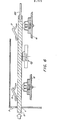
- the sleeve 12 is inserted now into the second slotted opening 8 ( Figures 8 and 9) and once inside the drive is guided rearward by guiding mechanism 70. During such movement, the sleeve contacts first the upper ramped surfaces 73' of the wedge shaped sections 73 of lowering mechanism 71 and then contacts the upper ramped surfaces 73' of the wedged shaped sections 73 of lowering mechanism 72, such contact causing the lowering mechanisms 7 and 72 to move downward and into contact with frame 16, whereby the frame/disk is forced downward. Just before the point of extreme downward movement of the frame is achieved, the disk 20 is seated on the spindle 400.
- the disk Since the spacing between the tabs 30 and 32 is slightly greater than the thickness of the disk 20, the disk is freed from the frame 16 when the disk is seated on the spindle 400. Once in contact with the spindle, the disk is held to the spindle by the magnetic field between the magnet 403 and the metallic annulus 21 of the disk.
- the disk is now ready for read/write operation in conjunction with a light source (not shown) that emits a pulsed beam for writing and a continuous wave beam for reading.
- a carriage (not shown) transports the light source radially across the disc.
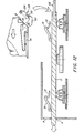
- the sleeve 12 When utilization of the disk 20 is completed, the sleeve 12 is withdrawn from the second slotted opening 8 ( Figure 10), such withdrawal removing the downward forces on the lowering mechanisms 71 and 72 and, in turn, the downward forces on the frame 16. Removal of such downward forces leaves the spring loaded supports 63 exerting upward forces on the frame 16 and those forces are sufficient to overcome the magnetic force between the spindle magnet 403 and the disk annulus 21 such that the frame and disk move upwardly from the spindle, with the supports 63 now supporting the frame 16.
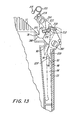
- Insertion of the empty sleeve 12 into the first slotted opening ( Figure 11 once again places the frame/disk within the sleeve. Since the latch members 204 and 207 are in their second stable position, nibs 48 are free to engage recesses 52 whereby the sleeve is again engaged to, or locked to, the frame. Subsequent withdrawal of the sleeve/frame/disc ( Figure 12) causes the protrusions 50 to strike legs 222 of members 207, causing a displacement of members 207 great enough to provide an over-center force to the latch mechanisms 203 to once again set the members of the latch mechanisms 203 in the first stable position such that the drive is ready for insertion of a new cartridge.
- Insertion of the sleeve into the second slotted opening 8 results in the sleeve contacting arm section 801 of latch member 800, causing the latch member to rotate with the result that arm section 802 moves into a position that prevents another cartridge from being inserted into the bottom slot 6 and also prevents access to the interior of the drive via slot 6 while the laser is in operation.
- a sensing mechanism 900 is associated with one of the interlock mechanisms 203 whereby a control signal is generated when the members of that interlock mechanism are forced into their second stable position.
- That signal energizes an electro-magnet 902, causing a pin 904 to be driven through a hole 906 in the side wall 66 and into contact with the frame 16 whereby the frame 16 cannot be removed from the drive until after the pin is withdrawn upon the latch members reverting to their first stable position.
Landscapes
- Feeding And Guiding Record Carriers (AREA)
- Holding Or Fastening Of Disk On Rotational Shaft (AREA)
Applications Claiming Priority (2)
| Application Number | Priority Date | Filing Date | Title |
|---|---|---|---|
| US42098582A | 1982-09-21 | 1982-09-21 | |
| US420985 | 1982-09-21 |
Publications (2)
| Publication Number | Publication Date |
|---|---|
| EP0118636A2 true EP0118636A2 (de) | 1984-09-19 |
| EP0118636A3 EP0118636A3 (de) | 1985-05-22 |
Family
ID=23668704
Family Applications (1)
| Application Number | Title | Priority Date | Filing Date |
|---|---|---|---|
| EP83305560A Withdrawn EP0118636A3 (de) | 1982-09-21 | 1983-09-21 | Optische Plattenkassette |
Country Status (2)
| Country | Link |
|---|---|
| EP (1) | EP0118636A3 (de) |
| JP (1) | JPS5965978A (de) |
Cited By (3)
| Publication number | Priority date | Publication date | Assignee | Title |
|---|---|---|---|---|
| EP0267644A1 (de) * | 1986-11-03 | 1988-05-18 | Koninklijke Philips Electronics N.V. | System für Aufnahme/Wiedergabe von Informationen auf eine/von einer Platte mit Plattenkassette und Gerät |
| EP0265896A3 (de) * | 1986-10-27 | 1989-07-26 | EASTMAN KODAK COMPANY (a New Jersey corporation) | Träger für Datenspeicherplatte |
| KR100851796B1 (ko) * | 2002-10-31 | 2008-08-13 | 산드빅 인터렉츄얼 프로퍼티 에이비 | 칩형성 기계가공용의 인덱서블 선삭 공구 |
Families Citing this family (2)
| Publication number | Priority date | Publication date | Assignee | Title |
|---|---|---|---|---|
| JPS648273U (de) * | 1987-07-03 | 1989-01-18 | ||
| US5936935A (en) | 1994-07-14 | 1999-08-10 | Matsushita Electric Industrial Co., Ltd. | Disk cartridge having a locking means and cartridge coupling means |
Family Cites Families (7)
| Publication number | Priority date | Publication date | Assignee | Title |
|---|---|---|---|---|
| US4164782A (en) * | 1978-08-21 | 1979-08-14 | Rca Corporation | Locking mechanism for record package |
| GB2042196B (en) * | 1979-02-15 | 1984-02-01 | Burroughs Corp | Latch mechanism for use with removable media |
| IT1131070B (it) * | 1979-04-06 | 1986-06-18 | Rca Corp | Meccanismo di manipolazione di dischi per un riproduttore di videodischi utilizzante una custodia portadisco |
| GB2046497B (en) * | 1979-04-06 | 1983-04-20 | Rca Corp | Video disc player having record handling mechanism |
| US4239108A (en) * | 1979-11-28 | 1980-12-16 | Rca Corporation | Video disc caddy |
| JPS6138133Y2 (de) * | 1980-05-15 | 1986-11-04 | ||
| JPS629565Y2 (de) * | 1980-08-20 | 1987-03-05 |
-
1983
- 1983-09-13 JP JP58167699A patent/JPS5965978A/ja active Pending
- 1983-09-21 EP EP83305560A patent/EP0118636A3/de not_active Withdrawn
Cited By (3)
| Publication number | Priority date | Publication date | Assignee | Title |
|---|---|---|---|---|
| EP0265896A3 (de) * | 1986-10-27 | 1989-07-26 | EASTMAN KODAK COMPANY (a New Jersey corporation) | Träger für Datenspeicherplatte |
| EP0267644A1 (de) * | 1986-11-03 | 1988-05-18 | Koninklijke Philips Electronics N.V. | System für Aufnahme/Wiedergabe von Informationen auf eine/von einer Platte mit Plattenkassette und Gerät |
| KR100851796B1 (ko) * | 2002-10-31 | 2008-08-13 | 산드빅 인터렉츄얼 프로퍼티 에이비 | 칩형성 기계가공용의 인덱서블 선삭 공구 |
Also Published As
| Publication number | Publication date |
|---|---|
| JPS5965978A (ja) | 1984-04-14 |
| EP0118636A3 (de) | 1985-05-22 |
Similar Documents
| Publication | Publication Date | Title |
|---|---|---|
| US4481617A (en) | Memory disc drive | |
| US4532564A (en) | Removable disk cartridge | |
| US4817079A (en) | Carrier retainer for disk cartridge | |
| JP2917488B2 (ja) | 光ディスク記録及び/又は再生装置 | |
| US5691860A (en) | Self sealing structure for a removable disk hard disk drive | |
| CA1109147A (en) | Cartridge loading mechanism | |
| DE69426638T2 (de) | Aufzeichnungs- und/oder Wiedergabegerät für Aufzeichnungsträger | |
| US4539614A (en) | Flexible magnetic disk clamping an injector mechanism | |
| EP0082505B1 (de) | Gerät zur Aufnahme einer Kassette | |
| US5636095A (en) | Removable disk to drive engagement | |
| EP0137311B1 (de) | Gerät zum Laden oder Entladen einer Magnetplattenpackung | |
| WO1987003414A1 (fr) | Cartouche de disques possedant un obturateur et dispositif d'ouverture et de fermeture de l'obturateur | |
| JPH0632181B2 (ja) | ディスク用キャリア | |
| US5291361A (en) | Disk drive with low elevated head unloading mechanism | |
| EP0118636A2 (de) | Optische Plattenkassette | |
| EP0351160A2 (de) | Plattenhalterung | |
| US4641212A (en) | Apparatus for loading a magnetic disc and for controlling the driving thereof | |
| US5335124A (en) | Disk drive | |
| EP0238752B1 (de) | Behälter für Datenspeicherelemente in Kombination mit einem Aufzeichnungs-/Wiedergabegerät zur Aufnahme des Behälters | |
| KR960008045B1 (ko) | 기록/플레이백 장치 | |
| EP1033708B1 (de) | Plattenaufzeichnungs- oder Wiedergabegerät | |
| KR100294442B1 (ko) | 기록매체용기록및재생장치와그장치에사용되는완충기구 | |
| US20010033443A1 (en) | Large capacity disk drive | |
| SU1578760A1 (ru) | Накопитель на гибком магнитном диске | |
| JPH06223473A (ja) | ディスクカートリッジ駆動装置 |
Legal Events
| Date | Code | Title | Description |
|---|---|---|---|
| PUAI | Public reference made under article 153(3) epc to a published international application that has entered the european phase |
Free format text: ORIGINAL CODE: 0009012 |
|
| AK | Designated contracting states |
Designated state(s): DE FR GB IT |
|
| PUAL | Search report despatched |
Free format text: ORIGINAL CODE: 0009013 |
|
| AK | Designated contracting states |
Designated state(s): DE FR GB IT |
|
| STAA | Information on the status of an ep patent application or granted ep patent |
Free format text: STATUS: THE APPLICATION HAS BEEN WITHDRAWN |
|
| 18W | Application withdrawn |
Withdrawal date: 19850904 |
|
| RIN1 | Information on inventor provided before grant (corrected) |
Inventor name: MABRY, C. THOMAS |