EP0119006A1 - Handhabungsvorrichtung für Münzen - Google Patents
Handhabungsvorrichtung für Münzen Download PDFInfo
- Publication number
- EP0119006A1 EP0119006A1 EP84300811A EP84300811A EP0119006A1 EP 0119006 A1 EP0119006 A1 EP 0119006A1 EP 84300811 A EP84300811 A EP 84300811A EP 84300811 A EP84300811 A EP 84300811A EP 0119006 A1 EP0119006 A1 EP 0119006A1
- Authority
- EP
- European Patent Office
- Prior art keywords
- coin
- coins
- gate
- gates
- control means
- Prior art date
- Legal status (The legal status is an assumption and is not a legal conclusion. Google has not performed a legal analysis and makes no representation as to the accuracy of the status listed.)
- Granted
Links
- 238000000926 separation method Methods 0.000 claims abstract description 29
- 230000004044 response Effects 0.000 claims description 8
- 230000001419 dependent effect Effects 0.000 claims description 7
- 230000008034 disappearance Effects 0.000 claims description 4
- 238000011144 upstream manufacturing Methods 0.000 claims description 2
- 238000001514 detection method Methods 0.000 description 4
- 230000008859 change Effects 0.000 description 3
- 230000007246 mechanism Effects 0.000 description 3
- 238000010586 diagram Methods 0.000 description 2
- 238000000034 method Methods 0.000 description 2
- 241000237858 Gastropoda Species 0.000 description 1
- 238000003745 diagnosis Methods 0.000 description 1
- 230000006870 function Effects 0.000 description 1
- 230000005484 gravity Effects 0.000 description 1
- 230000001939 inductive effect Effects 0.000 description 1
- 230000002401 inhibitory effect Effects 0.000 description 1
- 238000001746 injection moulding Methods 0.000 description 1
- 230000002452 interceptive effect Effects 0.000 description 1
- 230000002265 prevention Effects 0.000 description 1
- 230000003134 recirculating effect Effects 0.000 description 1
Images


Classifications
-
- G—PHYSICS
- G07—CHECKING-DEVICES
- G07D—HANDLING OF COINS OR VALUABLE PAPERS, e.g. TESTING, SORTING BY DENOMINATIONS, COUNTING, DISPENSING, CHANGING OR DEPOSITING
- G07D3/00—Sorting a mixed bulk of coins into denominations
- G07D3/14—Apparatus driven under control of coin-sensing elements
-
- G—PHYSICS
- G07—CHECKING-DEVICES
- G07F—COIN-FREED OR LIKE APPARATUS
- G07F5/00—Coin-actuated mechanisms; Interlocks
- G07F5/24—Coin-actuated mechanisms; Interlocks with change-giving
Definitions
- This invention relates to a coin handling apparatus.
- coin is used herein to cover not only genuine coins, but also tokens, slugs and other items of similar shapes and/or sizes to genuine coins.
- the invention is particularly, but not exclusively, applicable to coin handling apparatus which includes means for storing coins, and especially means for storing and dispensing coins of one or more particular denominations.
- Such means are commonly provided for receiving coins from a validator and subsequently dispensing the coins as change in, for example, vending machines, gaming machines and machines specifically designed solely for change-giving purposes.
- US-A-3916922 describes several embodiments of coin handling apparatus, one of which comprises a succession of gates for sorting.coins.
- the first sorting stage comprises a single gate which segregates acceptable and non-acceptable coins.
- the second sorting stage comprises two individually controllable gates for sorting the acceptable coins into three paths, and the third sorting stage comprises three gates having a common actuator for sorting the acceptable coins received from the second stage into six separate paths. If a coin container at the exit of one of these paths is full, then coins which are normally destined for that container are instead diverted at the second sorting stage to an alternate path.
- Another problem with this prior art arrangement is that there is no provision for delivering those coins which are normally sent to storage containers to respective, individual cashboxes when the associated containers are full.
- a coin handling apparatus comprising a plurality of supply passages each for supplying coins to a first passage or a second passage, each supply passage having a gate so that coins from the supply passage enter the first or the second passage depending upon whether the gate is in a first or a second position, a common actuator for said gates, the common actuator having a first state in which all said gates are in their respective first positions and a second state in which all said gates are in their second positions, and control means responsive to receipt by the apparatus of a coin for determining, in accordance with at least the type of the coin, the state to be adopted by the actuator and for controlling said actuator in such a manner that the actuator is in that state for at least a predetermined period sufficient to ensure that the coin enters the appropriate one of the first and second passages, characterised in that the apparatus is arranged such that first and second coins can arrive at the gates within an interval which is shorter than said predetermined period, and in that the control means is arranged to ensure that in those-circumstances,
- the apparatus can handle coins rapidly using an inexpensive gate arrangement driven by a single actuator.
- This aspect of the invention has uses in a variety of areas, but is particularly useful for a coin storage assembly in which the first passages lead to respective containers, and the second passages to alternate destinations used when the containers are full. Giving priority to the routing of coins to second passages might result in one or other container filling more slowly than it would otherwise, because occasionally a coin intended for that container will instead be delivered to the respective second passage, but this is of no practical disadvantage.
- the gates are shifted toward the position for delivering coins to the second passages in sufficient time to ensure that the second coin is in fact delivered correctly.
- the gate By the time the first coin reaches the gate, the gate could be fully shifted to the position at which coins are delivered to the second passage, or could be in an intermediate position.
- the destination of the first coin may therefore be indeterminate, but because it was originally intended for the container, and as mentioned above there will be no disadvantage in delivering it to the second passage, this does not matter.
- the gate is controlled in such a manner that it is ensured that the first coin enters the second passage.
- the gate is preferably then left in that position so that the second coin goes into its second passage, unless the spacing between the coins is such as to ensure that there is adequate time to shift the gate to its other position before arrival of the second coin.
- the second coin might go either to the container or to the second passage, but again this is not of any practical disadvantage.
- each gate preferably has a coin deflecting surface which is arranged so that it is in the path of coins, and thus deflects them, in order to direct the coins to the first passage, and is out of the path of the coins when they are to be delivered to the second passage so that they can proceed to that passage without deflection by the gate.
- the gate is preferably such that it is pivoted for movement between its first and second positions, and the axis of the pivot is upstream of the gate's coin deflecting surface.
- the common actuator is arranged so that the gates are all in the position in which they allow coins to enter the second passages when the actuator is de-energized.
- All the containers may be provided with a gate operated by the common actuator, or alternatively there may be a group of the containers associated with the gates operated by the common actuator, and one or more other containers having gates operated by one or more other actuators.
- the advantages of using a common actuator for several gates can be achieved without detrimentally affecting the rate at which coins can pass through the coin handling apparatus.
- the apparatus could be arranged so that the rate at which coins pass through the apparatus is limited to such an extent that the common actuator can be operated in the correct manner for each coin without interfering with the routing of the subsequent coin.
- the arrangement referred to above is preferably provided.
- a coin handling apparatus has separation means for directing coins of different types to respective destinations, and is arranged such that a subsequent coin is not sent to the separation means until a predetermined interval has elapsed from the separation means having received a preceding coin, wherein the interval is dependent upon the type of the preceding coin and/or the type of the subsequent coin.
- the maximum coin handling rate may vary in dependence upon the types of coins being handled. It is therefore possible to optimise the handling rate in accordance with the physical structure of the separating means.
- the apparatus may be arranged such that successive coins of the same denomination, which are routed through the separation means in the same manner, are allowed to be sent to the separation means at a faster rate than coins of different denominations,which are routed in a different manner which may require more time, e.g. for operating gates.
- the maximum rate at which coins are sent to the separation means may be controlled by causing a coin to be rejected instead of being sent to the separation means if it is received within a predetermined interval of a preceding coin being sent to the separation means. It would be possible alternatively to delay the subsequent coin until the end of the predetermined interval, and then send it to the separation means.
- a convenient way of implementing this aspect of the invention would be to generate, each time a coin is sent to the separation means, an inhibit signal having a period which determines the maximum rate at which coins can be handled by the apparatus. Any further coins which are received during that interval are not permitted to pass to the separation means. At the end of that interval, there will be a second predetermined interval in which only a coin of one or more selected types, the selection depending upon the nature of the coin which has already been sent to the separation means, would be delivered to the separation means. To determine whether a coin may be sent to the separation means during this interval, each coin may have assigned to it a code, referred to herein as a "block code". This would be determined in accordance with the path taken by that coin through the separation means. The code would indicate which coins could subsequently be sent to the separation means during the second interval referred to above.
- any type of coin is permitted to be sent to the separation means.
- This aspect of the invention is particularly useful in coin handling apparatus which incorporates storage means for storing coins of different denominations.
- a coin handling apparatus has control means for causing a diverting means selectively to direct coins to a first destination or to an alternative destination dependent upon whether a predetermined condition exists, wherein the control means is operable to allow successive coins to reach the diverting means at intervals equal to or greater than a first predetermined interval, and is responsive to the appearance or the disappearance of said predetermined condition for preventing, for a second, greater predetermined interval, a further coin from being presented to said diverting means to allow time for the diverting means to adopt a condition in which subsequent coins are directed to the appropriate destination.
- the first destination is preferably a coin storage means
- the predetermined condition may be a signal indicating that the coins in the storage means exceed a predetermined amount, e.g. that the storage means is full or nearly full. This may be provided by a level sensor.
- the prevention of further coins from being presented to the diverting means occurs in response to the level sensor indicating that the storage means is no longer full or nearly full.
- Coins can be prevented from reaching the diverting means during the second predetermined interval by delaying them, or preferably by rejecting them. In the preferred embodiment, by rejecting a single coin, enough time is provided to allow the diverting means to adopt the state in which subsequent coins are sent to the appropriate destination.
- the diverting means is preferably a gate arranged in the manner set out above in order that jamming does not occur when it moves from one of its positions to its other position. Accordingly, coins can very rapidly be sent to the diverting means, and the flow of coins switched between the two destinations without jamming occurring. When the flow is switched from one destination to another, jamming is avoided because the control means allows adequate time for the switching to occur before allowing a further coin to reach the diverting means, and when the flow is switched in the other manner jamming does not occur because of the structure of the gate.
- control means could be arranged so as to prevent, for a predetermined interval, further coins from being presented to the diverting means on both the appearance and the disappearance of the detection output. This however is not preferred, because it slightly reduces further the effective rate at which the coins are handled.
- a coin handling apparatus is operable to receive coins and to direct the coins to one or more destinations unless any one of a number of predetermined conditions exists, the apparatus further including means operable, each time a coin is not delivered to the appropriate destination because of the existence of one of said predetermined conditions, to generate a data signal the content of which is indicative of which of said predetermined conditions exists.
- the data signal may be provided at an output for delivery to a device for processing and/or storing the signal.
- the coin handling apparatus itself may include means for storing the signal, and preferably for storing a plurality of such signals.
- the signal provides an indication of why a coin has not been delivered to its correct destination. It is envisaged that this aspect of the invention will be particularly useful for providing, in an apparatus which has been found repeatedly to reject more coins than would normally be expected, an indication of why such rejection occurs.
- the handling apparatus may be arranged so that coins are rejected if it is discovered that gate-operating solenoids are not receiving sufficient power, if an inhibit signal has been generated because a sensor in the apparatus has detected that a previously-accepted coin has remained in the coin path, because a host machine in which the apparatus is installed is for some reason generating an inhibit signal, and for various other reasons. If the apparatus repeatedly provides a signal indicating that rejection has occurred because of, e.g., the first of these conditions, this will provide an immediate indication to anyone servicing the machine as to the general area in which a fault in the apparatus may lie. Accordingly, fault diagnosis is made much easier.
- the coin handling apparatus 100 comprises a validator 102, a separator 104 and a coin storage assembly 106.
- the validator receives coins via a hopper 108 and validates them using coils at a testing station 110.
- the apparatus is intended for use with five different types of coins, referred to herein as types A, B, C, D and E.
- types A, B, C, D and E are five different types of coins, referred to herein as types A, B, C, D and E.
- type B is in fact a coin-like token.
- an accept gate 112 is opened so that the coin enters a main entrance path 114 of the separator 104.
- the coin is then routed in the separator 104 in a manner to be described more fully below, and is then delivered to an appropriate one of several entrances of the coin storage assembly 106. If the validator 102 finds an inserted coin to be unacceptable, the accept gate 112 remains closed and the rejected coin delivered via a path 116 to a further entrance of the coin storage assembly 106.
- the paths taken by the respective coins A to E and the rejected coins F are illustrated in Figures 1 and 2.
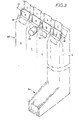
- the coin storage assembly 106 is illustrated more fully in Figures 3 and 4.
- Coins which are intended to be stored in the assembly 106 are delivered thereto via_respective supply passages 4 of the separator 104.
- the assembly 106 of the present embodiment comprises a plurality of, and in this particular case four, storage units 6.
- Each unit 6 has a storage space 8 for storing a stack 10 of coins received from a supply passage 4, a secondary passage 12 which can also receive coins from the supply passage 4, and an additional passage 14.
- the stacked coins in the storage space 8 can be dispensed one at a time by a dispensing mechanism generally indicated at 16.
- Coins from a supply passage 4 are normally delivered to the storage space 8, but if the storage space is full they are instead delivered to the secondary passage 12, which leads to a cashbox.
- each secondary passage 12 leads to an individual cashbox. Instead, they could all lead to a common destination (e.g. a single cashbox), and indeed there could be a single large secondary passage 12 into which coins from all the passages 4 can be led, instead of separate, individual passages 12.
- a gate 18 determines whether the coins from a respective supply passage 4 go to the storage space 8 or the secondary passage 12.
- Some additional passages 14 receive coins from respective separator passages 20. These coins may be of a denomination which the apparatus is not required to dispense, and the coins may be routed by the additional passages 14 to individual cashboxes, or a'common cashbox.
- the additional passage 14 of one of the units 6 is used to route the coins F which have been rejected by the validator 102 to an exit slot for retrieval by the user of the apparatus; thus, the separator passage 20 for this unit corresponds to the passage 116 of Figure 1.
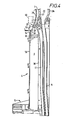
- Each unit 6 is formed in two longitudinal halves.
- Figure 4 shows the left-hand half of one of the units. Each half is formed by injection moulding.
- the storage space 8 is cylindrical, and has a diameter which is slightly greater than that of the coins intended to be stacked in the space.
- the coins from the supply passage 4 reach the storage space 8 via an entry 22.
- the entry 22 comprises a narrow space 24 between a wall 26 of the separator 104 and a ledge 28 at the upper end of an inner wall 30 of the storage unit.
- the shape and size of the space 24 are such that coins can pass through the space only if they are travelling edge-first.
- the coin 50 is supported in a generally upright, but inclined orientation with its centre of gravity located over the stack 10.
- An inwardly-inclined, flat upper edge 54 of an outer wall 56 of the storage unit assists in guiding the coin 50 to this orientation.
- An inductive sensor 52 is mounted in the separator in such a position that it will be in proximity to the face of the coin 50. The sensor 52 is able to detect the presence of coin 50 which indicates that the storage space 8 is full, which detection is reliable because the position of the last coin to enter the storage space is predetermined by the configuration of the entry 22 in co-operation with the stack 10.
- the upper edge of the coin 50 will no longer be supported by the ledge 28, and the coin will then fall directly face- down on the top of the stack.
- the sensor 52 will thus indicate that the space 8 is no longer full.
- the gates 18 of the four storage units 6 are all mechanically connected together, and indeed may be integrally formed.
- the gates all have a common actuator, which is a solenoid 60.
- the gates are all pivoted about a common axis 62 located near the upper ends of the gates.
- the gates 18 adopt the positions shown in phantom in Figure 4. In this position, the gates do not obstruct the travel of the coins from the supply passages 4, which therefore all fall into the respective secondary passages 12.
- the operation of the apparatus is such that there may be occasions upon which a coin originally intended to go to the storage space 8 arrives at the gate 18 while the gate is moving away from the position shown in solid lines in Figure 4.
- the coin may be deflected into the entrance 22 of the storage space 8, or be allowed to enter the secondary passage 12. It is possible also that the coin could come to rest on top of the edge 28 of the wall 30. In this case, however, the next time the solenoid 60 is energized, the gate 18 will knock the coin toward the storage space 8 (which is the originally-intended destination of the coin). Accordingly, the arrangement ensures that no jamming or overfilling of the coin storage space 8 will occur.
- the coins pass a detector 120, known as a "post-gate strobe", the output of which is used for timing purposes as will be described more fully below.
- the separator 104 has a routing gate 122 which remains closed when the incoming coins are of type A or B. These coins thus roll down an upper ramp 124 of the separator 104.
- the ramp 124 has a slot which permits only coins B to pass therethrough, so that the coins A and B are separated and sent to respective storage units 6.
- Each of the coins A and B can pass into a respective storage space 8 or secondary passage 12 depending on the position of a respective gate 18.
- the gate 122 is opened so that the coins drop onto a lower separator ramp 126.
- a window at the side of the ramp and a slot in the bottom of the ramp separate the coins C, D and E.
- the coins D and E which are not required for dispensing, are led to additional passages 14 of respective units 6, which deliver the coins to one or more cashboxes.
- the coins C are led to a gate 18 over one of the storage units 6 so that the coins C can be directed either to a storage space 8 or a secondary passage 12.
- the rejected coins F are directed to an additional passage 14 in an otherwise-unused coin storage unit 6.
- FIG. 5 shows in schematic form the circuit of the coin handling apparatus.
- the circuit comprises a control unit 200 and a coin validator circuit 202.
- the control unit 200 includes a microprocessor 204, e.g. a mask-programmed Intel type 8048. This is connected via an input/output bus 206 to an interface unit 212.
- the interface 212 receives from the validator 202 on lines 214 an accept signal Acc which indicates that a valid coin has been received, and signals indicating which of the types A to E the valid coin belongs to.
- the interface 212 delivers to the validator 202 on line 216 a master inhibit signal MI which terminates the accept signal Acc if the latter is presently being generated, and prevents the validator from generating a further accept signal Acc while the signal MI is present.
- MI master inhibit signal
- the interface 212 receives a signal from the post-gate strobe detector 120, and signals from pay-out sensors 218.
- Each of the pay-out sensors is mounted beneath the respective dispensing mechanism 16 of a coin storage unit 6 to detect when a coin has been paid out by the dispensing mechanism.
- the interface 212 sends strobe signals on lines 220 to actuate respective ones of the sensors 52 shown collectively at 222, and receives on line 224 an output signal indicating the state of the respective sensor which has been actuated by a strobe signal.
- the interface 212 also sends signals on lines 226 to the solenoid 60 of the gates 18 and the solenoid used to actuate the routing gate 122. These solenoids are shown collectively at 228.
- the interface 212 also serves the function of actuating the solenoid 230 of the accept gate 112 in response to the accept signal Acc.
- the coin handling apparatus is installed in a host machine, in this particular case a gaming machine, to which the circuit is connected via output lines 232 and input lines 234.
- the output lines 232 deliver to the host machine various information, including information indicative of the types of coins which the apparatus as a whole has accepted so that this information can be used for accumulating a user's credit count.
- the information also includes "diagnostic" information which will be described more fully below.
- the input lines 234 carry signals which can be used to inhibit the acceptance of any one of the five coins A to E.
- This inhibiting operation by the host machine- may be desirable in certain circumstances; for example the machine may be arranged to inhibit acceptance of high-value coins if there are insufficient low-value coins to pay out the correct change.
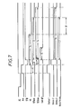
- Figures 6 and 7 respectively show a main program loop and a timing chart for the microprocessor 204.
- Figure 7 illustrates the overall operation of the circuit on receipt of a valid coin. It should be noted that this chart applies when a single coin passes through the coin handling apparatus, and when the coin requires operation of both the routing gate 122 and the diverter gates 18.
- the validator circuit 202 is similar to that described in GB-A-2093620, and generates a power-up signal Pu in response to the arrival of a coin in the validator.
- the power-up signal terminates as the coin leaves the testing station 110 of the validator.
- the validator generates the accept signal Acc, assuming that the coin has been tested and found to be valid.
- the accept signal results in the solenoid 230 operating the accept gate 112, so that the coin falls past the post-gate strobe detector 120, which thus generates a strobe signal STB.
- the microprocessor 204 is operable, after the power has been turned on, to execute an initialisation routine 250 and then repeatedly to circulate through a main program loop indicated generally at 252.
- the program successively checks "status 1", "status 2" and “status 3" flags at steps 254, 258 and 262, and if any is set a respective program routine 256, 260 or 264 is executed. The program then executes a routine indicated at 266 before re-entering the program loop 252.
- an interrupt routine responds to the signal Acc by causing an 'accept' timer to be started, setting various registers in accordance with the desired routing of the coin, and setting the status 1 flag. The latter operation will cause the program routine 256 to be executed each time the program executes the main loop 252.
- the microprocessor checks the strobe signal STB from the detector 120, and if it is determined that a coin is adjacent the detector 120, the status 1 flag is reset and the status 2 flag is set. The program section 256 will thus no longer be entered during the next execution of the main program loop.
- the program section 256 determines that the "accept" timer has timed out before the signal STB indicates the presence of a coin, it is assumed that a fault has occurred and a reject routine is executed. This routine involves clearing the status 1 flag and issuing the master inhibit signal MI which prevents the validator from accepting further coins for the present. Also, the microprocessor 204 delivers to the host machine on lines 232 a code indicating that rejection has occurred because of a timeout of the accept timer.
- the program section 260 will be entered each time the main loop is executed. This section causes the generation of the master inhibit signal MI so that the. accept signal Acc is terminated and no further coin can be accepted for the present.
- the program section 260 also monitors the strobe signal STB. If during the execution of this program section the strobe signal STB indicates that there is no longer a coin adjacent the detector 120, the status 2 flag is cleared and the status 3' flag set.
- the subsequent repeated execution of the main program loop then causes the status 3 program section 264 to be executed.
- timers are checked in order to control the routing gate 122 and the diverter gates 18.
- the status 3 program section 264 also causes a coin output signal to be delivered to the host machine for a predetermined duration, this signal indicating the type of the accepted coin, and further causes a "block signal" to be generated for a predetermined block period.
- the status 3 program section is operable also to clear the status 3 flag after a predetermined time. Subsequent execution of the main program loop will then result in all three status flags being found clear, and the program will then proceed to step 266 before recirculating.
- the step 266 is executed in order to check certain timers, including one which, when it times out after a period T1, terminates the master inhibit signal MI, and another which, if an incoming coin is of an appropriate type, times out after a period P1, at which point the routing gate 122 is operated.
- the step 266 is also executed to perform various "housekeeping" tasks, such as communicating with the host machine, etc.
- the operation of the microprocessor is periodically interrupted at regular intervals, so that the program flow is temporarily switched to an interrupt routine shown in Figure 8 before returning to the main program loop.
- This interrupt is generated by a timer internal to the microprocessor 204.
- the main purpose of the interrupt routine is to update various memory locations used as timers within the microprocessor 204, to check the sensors 218 and to execute a coin acceptance program routine if an accept signal Acc has been received from the validator 202.
- the various timers are updated, and one of the sensors 52 is checked, at step 300.
- the sensors 52 are checked in succession, one each time the interrupt routine is executed.
- step 301 the program checks whether the Acc signal is present. If not, the interrupt routine terminates. Otherwise, the program proceeds to step 302, where the status 1 flag is checked. If this is not set, the program proceeds to the coin acceptance routine, which starts at step 303.
- the coin data from the validator which indicates the type of coin received, is checked and the coin type noted.
- the microprocessor checks whether the detector 120 detects the presence of a coin. This should not occur under normal operation of the machine, and therefore if a coin is detected it is assumed that a faulty operation has occurred and the program proceeds to the reject path 310 to prevent further coins from being accepted.
- the program checks whether an external inhibit signal from the host machine or an internally-generated inhibit signal is present, and in either case if a signal is present the program proceeds to the reject path 310.
- the program compares the data representing the type of the coin with a previously- stored block code. This is done by logically combining a code representing the coin type with the block code. Depending upon the result of the logical comparison, the program either enters the reject path 310 or proceeds to block 312. A more detailed explanation of the step 308 is given below.
- the program starts the accept timer, which was referred to above.
- step 314 is executed to determine whether the incoming coin is of type D or E. These are the coins which are sent to additional passages 14 in the coin storage units 6. If the coin is either of these types, the program proceeds to step 316. At the latter step, the program stores a signal representing that the normally-open routing gate 122 and the diverter gates 18 need not be operated. The program also stores a coin data code representing the coin type, and looks up in a table a "block code" associated with the coin, and stores that block code for use during a subsequent execution of step 308, i.e. when a further coin has been accepted by the validator- 202. These codes will eventually be cleared at the end of the block period shown in Figure 7.
- step 314 the program determines whether the appropriate storage space 8 for that coin (which would be of type A, B or C) is full.
- step 320 This is similar to step 316, except that in this case the operation of the routing gate 122 will be dependent upon whether or not the coin is of type C. If it is not, the operation of the routing gate 122 is required, and the program starts the timer which times the period P1 shown in Figure 7.
- step 318 If the appropriate tube is not full, as indicated by the output of the respective sensor 52, the program proceeds from step 318 to step 322.
- the coin data code for the previously-accepted coin is used in step 322 for determining whether a coin of type A, B or C is currently being routed to the cashbox. As mentioned above, this code is automatically cleared after a certain time, so that a positive answer will be obtained only if the succeeding coin arrives within a predetermined interval of the preceding coin being directed to the cashbox.
- step 324 This is similar to step 320, except that in this case it is desired that the incoming coin be directed to the appropriate one of the coin storage spaces 8, so that the program stores an indication that the diverter gates 18 are to be operated.
- step 322 If, on the other hand, it is determined that a coin of type A, B or C is currently being routed to the cashbox, the program proceeds from step 322 to step 326. At this point it is determined whether the preceding coin is of the same type as the coin which has just arrived.
- step 326 will be reached in either of the following two conditions:
- step 330 the status 1 flag is cleared and the status 2 flag set.
- the clearing of the status 1 flag means that the coin acceptance routine starting at step 303 will not be entered until a further coin causes a new accept signal Acc to be generated.
- the reject path 310 proceeds to a step 334, and as a consequence of reaching this step the microprocessor issues the master inhibit signal for a predetermined time to prevent any more coins from being accepted during this interval, and clears any registers which are used to determine the operation of the gates and to store the coin and block codes.
- the microprocessor is caused to output on lines 232 a code indicative of the reason for rejection. For this purpose, an appropriate code is stored in a register before the main reject path 310 is reached, the storing operation occurring at one of steps R1 to R5 depending upon the reason for rejection.
- the validator circuit 202 is so arranged that, having determined that an incoming coin is acceptable, it will not accept any further coin until the leading edge of the strobe signal STB. It will then be prevented by the control unit 200 from validating further coins for the period of the master inhibit signal MI.
- the microprocessor 204 After a coin has been accepted and up until the end of the block period, the microprocessor 204 stores the block code and the coin data code for that particular coin.
- the coin data code may be a five bit code having only one bit set, that bit corresponding to the coin type.
- coin type A may be represented by coin data 00001, B by coin data 00010, etc.
- the block code also has five bits, each bit representing a particular coin type.
- the block code is determined for a particular coin in accordance with the structure of the separator. After receiving the coin in question, there will be certain coins which the separator can thereafter handle very quickly and the bit in the block code corresponding to each of these coins is reset. The remaining bits are set.
- the coin data code for the coin type C is 00100. If a coin of type C has been handled by the separator 104, a coin of type D or E can be thereafter handled very quickly, because neither of these requires operation of the gate 122 or any of the gates 1 8. Accordingly, the block code for the coin C is 00011, which indicates that any coin except those of types A and B can be handled very quickly after a coin of type C.
- step 308 of the status 1 routine the block code of the previously-accepted coin is ANDed with the coin code of the newly-arrived coin. If the result of this is zero (as would be the case if a coin of type C were followed by a coin of type C, D or E), the program proceeds to step 312. If the result is not equal to zero, this indicates that the subsequent coin is not of a type which can be handled very rapidly after the preceding coin, and therefore the program proceeds to the main reject path 310.
- the period B1 is sufficiently-long in relation to the preceding period in which coins are prevented from being sent to the separator, there is a possibility that a third coin will be sent to the separator during the period B1 established by the first coin.
- the period B1 could be so long that there is sufficient time within that period for a second coin to arrive, for the period B1 established by the second coin to be established, and for a third coin to arrive and be directed to the separator before the time at which the period B1 established by the first coin would have expired.
- the problem is avoided by arranging, each time a block code is stored, for that block code to be ORed with the presently stored block code.
- the block codes for the first and second coins would be ORed, and the resultant code compared in step 308 with the coin data code for the third coin.
- the third coin would therefore only be sent to the separator if its routing would not interfere with either the first or the second coin.
- the program step 266 shown in Figure 6 is repeatedly executed during and after the status 1, status 2 and status 3 periods, any decision-taking made during those program sections can be altered during subsequent execution of the main program loop. This is particularly important in that it allows a change in the routing of a coin in response to changes in the present conditions of the apparatus.
- the program step 266 includes a routine for checking the statuses of the sensors 52. If a storage space 8 receives a coin of a particular type which causes the storage space to be full, and a coin of the same type has just been received, an initial decision to direct the coin to the storage space can be altered so that the coin is instead directed to the cashbox.
Landscapes
- Physics & Mathematics (AREA)
- General Physics & Mathematics (AREA)
- Control Of Vending Devices And Auxiliary Devices For Vending Devices (AREA)
Priority Applications (1)
| Application Number | Priority Date | Filing Date | Title |
|---|---|---|---|
| AT84300811T ATE27070T1 (de) | 1983-02-08 | 1984-02-08 | Handhabungsvorrichtung fuer muenzen. |
Applications Claiming Priority (4)
| Application Number | Priority Date | Filing Date | Title |
|---|---|---|---|
| GB08303370A GB2135096B (en) | 1983-02-08 | 1983-02-08 | Coin storage assembly |
| GB08333857A GB2137793B (en) | 1983-02-08 | 1983-12-20 | Coin handling apparatus |
| GB8303370 | 1983-12-20 | ||
| GB8333857 | 1983-12-20 |
Publications (2)
| Publication Number | Publication Date |
|---|---|
| EP0119006A1 true EP0119006A1 (de) | 1984-09-19 |
| EP0119006B1 EP0119006B1 (de) | 1987-05-06 |
Family
ID=26285160
Family Applications (1)
| Application Number | Title | Priority Date | Filing Date |
|---|---|---|---|
| EP19840300811 Expired EP0119006B1 (de) | 1983-02-08 | 1984-02-08 | Handhabungsvorrichtung für Münzen |
Country Status (5)
| Country | Link |
|---|---|
| EP (1) | EP0119006B1 (de) |
| JP (1) | JPH0772917B2 (de) |
| DE (1) | DE3463581D1 (de) |
| GB (1) | GB2137793B (de) |
| HK (1) | HK42992A (de) |
Cited By (7)
| Publication number | Priority date | Publication date | Assignee | Title |
|---|---|---|---|---|
| FR2611950A1 (fr) * | 1987-03-06 | 1988-09-09 | Jofemar Sa | Selecteur-separateur de pieces de monnaie |
| EP0477731A3 (en) * | 1990-09-25 | 1992-09-30 | Coin Acceptors, Inc. | Coin tube monitor and control means |
| WO1993018487A3 (fr) * | 1992-03-11 | 1994-02-17 | Atoll Technology | Dispositif pour la separation des pieces, jetons et analogues et appareils de paiement automatique |
| EP0590380A1 (de) * | 1992-09-24 | 1994-04-06 | National Rejectors Inc. GmbH | Münzgerät, insbesondere Geldwechsler |
| EP0557960A3 (en) * | 1992-02-28 | 1994-08-17 | Sanyo Electric Co | Coin processor for use with automatic vending machines |
| GB2383672A (en) * | 2001-11-22 | 2003-07-02 | Asahi Seiko Co Ltd | Dispensing discs such as coins |
| EP1205887A3 (de) * | 2000-11-09 | 2004-05-12 | Sanden Corporation | Münzweiche |
Families Citing this family (8)
| Publication number | Priority date | Publication date | Assignee | Title |
|---|---|---|---|---|
| GB2154353A (en) * | 1984-02-17 | 1985-09-04 | Appliance Components Ltd | Coin separator |
| ES1009365Y (es) * | 1988-11-28 | 1990-02-16 | Jofemar , S.A. | Seleccionador de monedas con devolvedor incorporado. |
| CA2013719A1 (en) * | 1989-04-06 | 1990-10-06 | James M Rasmussen | Bag switching system for coin sorting apparatus |
| GB2235324B (en) * | 1989-07-13 | 1993-08-18 | Mars Inc | Device for guiding coins |
| GB2246898B (en) * | 1990-08-10 | 1994-02-23 | Mars Inc | Coin mechanism |
| CA2048743C (en) * | 1990-08-14 | 1996-08-27 | Kenji Nishiumi | Coin selector |
| GB2348730B (en) | 1999-04-07 | 2003-02-19 | Mars Inc | Currency handling apparatus |
| EP1956107B1 (de) * | 2007-01-31 | 2019-06-26 | Nippon Light Metal Company, Ltd. | Aluminumpulverlegierungsverbundmaterial für die Absorption von Neutronen , sein Herstellungsverfahren und Korb aus diesem Material |
Citations (8)
| Publication number | Priority date | Publication date | Assignee | Title |
|---|---|---|---|---|
| GB1328051A (en) * | 1971-06-14 | 1973-08-30 | Vendo Co | Coin handling apparatus having an alternating feed for coins or the like |
| US3916922A (en) * | 1973-06-20 | 1975-11-04 | Georg J Prumm | Electronic coin tester |
| US3948377A (en) * | 1973-01-17 | 1976-04-06 | Nippon Coinco Co., Ltd. | Coin handling apparatus for a vending machine |
| US4056181A (en) * | 1975-03-17 | 1977-11-01 | Sanyo Electric Co., Ltd. | System and method for determining vendibility in automatic vending machine |
| US4106610A (en) * | 1976-06-07 | 1978-08-15 | Mars, Incorporated | Coin apparatus having multiple coin-diverting gates |
| US4228811A (en) * | 1977-06-07 | 1980-10-21 | Fuji Electric Co., Ltd. | Apparatus for controlling a coin sorting machine |
| DE2928644A1 (de) * | 1979-07-16 | 1981-02-12 | Paul Gauselmann | Geldbetaetigter automat, insbesondere spielautomat |
| US4286703A (en) * | 1979-05-11 | 1981-09-01 | Umc Industries, Inc. | Coin testing and sorting apparatus |
Family Cites Families (7)
| Publication number | Priority date | Publication date | Assignee | Title |
|---|---|---|---|---|
| GB994736A (de) * | 1962-11-27 | 1965-06-10 | Tateisi Denki Kabushikikaisha | |
| DE2029751C3 (de) * | 1970-06-16 | 1974-11-07 | Adolf 8150 Roggersdorf Hinterstocker | Elektronischer Münzprüfer mit einer einzigen Prüfvorrichtung |
| JPS5294196A (en) * | 1976-02-03 | 1977-08-08 | Glory Kogyo Kk | Means for controlling supplementary feed of coins for coin assorting and delivering machines |
| JPS5491399A (en) * | 1977-12-02 | 1979-07-19 | Pruemm Georg Jakob | Coin extinguishing apparatus |
| JPS5724668A (en) * | 1980-07-21 | 1982-02-09 | Hitachi Ltd | Method and device for coating |
| JPS5688589A (en) * | 1979-12-19 | 1981-07-18 | Sanyo Jido Hanbaiki Kk | Coin selector |
| JPS57152087A (en) * | 1981-03-14 | 1982-09-20 | Shinko Electric Co Ltd | Vending machine |
-
1983
- 1983-12-20 GB GB08333857A patent/GB2137793B/en not_active Expired
-
1984
- 1984-02-08 EP EP19840300811 patent/EP0119006B1/de not_active Expired
- 1984-02-08 DE DE8484300811T patent/DE3463581D1/de not_active Expired
- 1984-02-08 JP JP59020115A patent/JPH0772917B2/ja not_active Expired - Lifetime
-
1992
- 1992-06-11 HK HK42992A patent/HK42992A/en not_active IP Right Cessation
Patent Citations (8)
| Publication number | Priority date | Publication date | Assignee | Title |
|---|---|---|---|---|
| GB1328051A (en) * | 1971-06-14 | 1973-08-30 | Vendo Co | Coin handling apparatus having an alternating feed for coins or the like |
| US3948377A (en) * | 1973-01-17 | 1976-04-06 | Nippon Coinco Co., Ltd. | Coin handling apparatus for a vending machine |
| US3916922A (en) * | 1973-06-20 | 1975-11-04 | Georg J Prumm | Electronic coin tester |
| US4056181A (en) * | 1975-03-17 | 1977-11-01 | Sanyo Electric Co., Ltd. | System and method for determining vendibility in automatic vending machine |
| US4106610A (en) * | 1976-06-07 | 1978-08-15 | Mars, Incorporated | Coin apparatus having multiple coin-diverting gates |
| US4228811A (en) * | 1977-06-07 | 1980-10-21 | Fuji Electric Co., Ltd. | Apparatus for controlling a coin sorting machine |
| US4286703A (en) * | 1979-05-11 | 1981-09-01 | Umc Industries, Inc. | Coin testing and sorting apparatus |
| DE2928644A1 (de) * | 1979-07-16 | 1981-02-12 | Paul Gauselmann | Geldbetaetigter automat, insbesondere spielautomat |
Cited By (11)
| Publication number | Priority date | Publication date | Assignee | Title |
|---|---|---|---|---|
| FR2611950A1 (fr) * | 1987-03-06 | 1988-09-09 | Jofemar Sa | Selecteur-separateur de pieces de monnaie |
| BE1003040A5 (fr) * | 1987-03-06 | 1991-11-05 | Jofemar Sa | Selecteur-separateur de monnaies. |
| EP0477731A3 (en) * | 1990-09-25 | 1992-09-30 | Coin Acceptors, Inc. | Coin tube monitor and control means |
| EP0557960A3 (en) * | 1992-02-28 | 1994-08-17 | Sanyo Electric Co | Coin processor for use with automatic vending machines |
| US5380242A (en) * | 1992-02-28 | 1995-01-10 | Sanyo Electric Co., Ltd. | Coin processor for use with automatic vending machines |
| WO1993018487A3 (fr) * | 1992-03-11 | 1994-02-17 | Atoll Technology | Dispositif pour la separation des pieces, jetons et analogues et appareils de paiement automatique |
| EP0731427A3 (de) * | 1992-03-11 | 1998-09-30 | Atoll Technology | Verfahren zur Erkennung von Objekten, wie zum Beispiel Münzen |
| EP0590380A1 (de) * | 1992-09-24 | 1994-04-06 | National Rejectors Inc. GmbH | Münzgerät, insbesondere Geldwechsler |
| EP1205887A3 (de) * | 2000-11-09 | 2004-05-12 | Sanden Corporation | Münzweiche |
| GB2383672A (en) * | 2001-11-22 | 2003-07-02 | Asahi Seiko Co Ltd | Dispensing discs such as coins |
| GB2383672B (en) * | 2001-11-22 | 2004-02-18 | Asahi Seiko Co Ltd | Disc guiding device |
Also Published As
| Publication number | Publication date |
|---|---|
| JPS59183483A (ja) | 1984-10-18 |
| DE3463581D1 (en) | 1987-06-11 |
| HK42992A (en) | 1992-06-19 |
| EP0119006B1 (de) | 1987-05-06 |
| GB2137793A (en) | 1984-10-10 |
| GB2137793B (en) | 1986-06-04 |
| GB8333857D0 (en) | 1984-02-01 |
| JPH0772917B2 (ja) | 1995-08-02 |
Similar Documents
| Publication | Publication Date | Title |
|---|---|---|
| EP0119006B1 (de) | Handhabungsvorrichtung für Münzen | |
| EP0134686B1 (de) | Münzprüfeinrichtung | |
| US4558711A (en) | Coin processing apparatus | |
| US4558712A (en) | Automatic coin depositing and paying machine | |
| US5579886A (en) | Coin processor | |
| US5052538A (en) | Coin handling apparatus | |
| US5496212A (en) | Coin sorting device | |
| US5356333A (en) | Coin storage device | |
| US4188962A (en) | Money dispensation control device | |
| US6702092B2 (en) | Coin assorter | |
| US5676234A (en) | Coin/token sorting method | |
| US5112275A (en) | Coin separator with means for detecting an erroneously separated coin | |
| US5597061A (en) | Coin processing apparatus | |
| JP3973861B2 (ja) | 硬貨入出金機 | |
| JP3953685B2 (ja) | 硬貨処理装置 | |
| JP4573235B2 (ja) | 硬貨処理装置 | |
| EP0542778B1 (de) | Münzbehandlungsvorrichtung | |
| GB2112195A (en) | Coin apparatus | |
| JP6056586B2 (ja) | 硬貨処理装置 | |
| EP0119712B1 (de) | Münzspeicheranordnung | |
| JP2970007B2 (ja) | 硬貨選別計数機およびその誤振り分け検出方法 | |
| JP7496255B2 (ja) | 硬貨処理装置 | |
| JP4137538B2 (ja) | 硬貨処理機 | |
| JP2024168429A (ja) | 硬貨処理装置、プログラム、および現金処理装置 | |
| JPH07121754A (ja) | 硬貨処理装置 |
Legal Events
| Date | Code | Title | Description |
|---|---|---|---|
| PUAI | Public reference made under article 153(3) epc to a published international application that has entered the european phase |
Free format text: ORIGINAL CODE: 0009012 |
|
| AK | Designated contracting states |
Designated state(s): AT BE CH DE FR GB IT LI LU NL SE |
|
| 17P | Request for examination filed |
Effective date: 19850304 |
|
| ITF | It: translation for a ep patent filed | ||
| GRAA | (expected) grant |
Free format text: ORIGINAL CODE: 0009210 |
|
| AK | Designated contracting states |
Kind code of ref document: B1 Designated state(s): AT BE CH DE FR GB IT LI LU NL SE |
|
| PG25 | Lapsed in a contracting state [announced via postgrant information from national office to epo] |
Ref country code: AT Effective date: 19870506 |
|
| REF | Corresponds to: |
Ref document number: 27070 Country of ref document: AT Date of ref document: 19870515 Kind code of ref document: T |
|
| PG25 | Lapsed in a contracting state [announced via postgrant information from national office to epo] |
Ref country code: SE Effective date: 19870531 |
|
| REF | Corresponds to: |
Ref document number: 3463581 Country of ref document: DE Date of ref document: 19870611 |
|
| ET | Fr: translation filed | ||
| PLBE | No opposition filed within time limit |
Free format text: ORIGINAL CODE: 0009261 |
|
| STAA | Information on the status of an ep patent application or granted ep patent |
Free format text: STATUS: NO OPPOSITION FILED WITHIN TIME LIMIT |
|
| 26N | No opposition filed | ||
| ITTA | It: last paid annual fee | ||
| PGFP | Annual fee paid to national office [announced via postgrant information from national office to epo] |
Ref country code: CH Payment date: 19920217 Year of fee payment: 9 |
|
| PGFP | Annual fee paid to national office [announced via postgrant information from national office to epo] |
Ref country code: NL Payment date: 19920229 Year of fee payment: 9 |
|
| PGFP | Annual fee paid to national office [announced via postgrant information from national office to epo] |
Ref country code: BE Payment date: 19920403 Year of fee payment: 9 |
|
| PGFP | Annual fee paid to national office [announced via postgrant information from national office to epo] |
Ref country code: LU Payment date: 19920416 Year of fee payment: 9 |
|
| EPTA | Lu: last paid annual fee | ||
| PG25 | Lapsed in a contracting state [announced via postgrant information from national office to epo] |
Ref country code: LU Free format text: LAPSE BECAUSE OF NON-PAYMENT OF DUE FEES Effective date: 19930208 |
|
| PG25 | Lapsed in a contracting state [announced via postgrant information from national office to epo] |
Ref country code: LI Effective date: 19930228 Ref country code: CH Effective date: 19930228 Ref country code: BE Effective date: 19930228 |
|
| BERE | Be: lapsed |
Owner name: MARS INC. Effective date: 19930228 |
|
| PG25 | Lapsed in a contracting state [announced via postgrant information from national office to epo] |
Ref country code: NL Effective date: 19930901 |
|
| NLV4 | Nl: lapsed or anulled due to non-payment of the annual fee | ||
| REG | Reference to a national code |
Ref country code: CH Ref legal event code: PL |
|
| REG | Reference to a national code |
Ref country code: GB Ref legal event code: IF02 |
|
| PGFP | Annual fee paid to national office [announced via postgrant information from national office to epo] |
Ref country code: GB Payment date: 20030205 Year of fee payment: 20 |
|
| PGFP | Annual fee paid to national office [announced via postgrant information from national office to epo] |
Ref country code: FR Payment date: 20030210 Year of fee payment: 20 |
|
| PGFP | Annual fee paid to national office [announced via postgrant information from national office to epo] |
Ref country code: DE Payment date: 20030220 Year of fee payment: 20 |
|
| PG25 | Lapsed in a contracting state [announced via postgrant information from national office to epo] |
Ref country code: GB Free format text: LAPSE BECAUSE OF EXPIRATION OF PROTECTION Effective date: 20040207 |
|
| REG | Reference to a national code |
Ref country code: GB Ref legal event code: PE20 |