EP0119366A1 - Toilettenvorrichtung mit einer hydraulischen Klappe eingebaut im Endteil eines Siphons - Google Patents
Toilettenvorrichtung mit einer hydraulischen Klappe eingebaut im Endteil eines Siphons Download PDFInfo
- Publication number
- EP0119366A1 EP0119366A1 EP83430030A EP83430030A EP0119366A1 EP 0119366 A1 EP0119366 A1 EP 0119366A1 EP 83430030 A EP83430030 A EP 83430030A EP 83430030 A EP83430030 A EP 83430030A EP 0119366 A1 EP0119366 A1 EP 0119366A1
- Authority
- EP
- European Patent Office
- Prior art keywords
- valve
- siphon
- rod
- jack
- bowl
- Prior art date
- Legal status (The legal status is an assumption and is not a legal conclusion. Google has not performed a legal analysis and makes no representation as to the accuracy of the status listed.)
- Withdrawn
Links
- XLYOFNOQVPJJNP-UHFFFAOYSA-N water Substances O XLYOFNOQVPJJNP-UHFFFAOYSA-N 0.000 claims abstract description 23
- 239000007788 liquid Substances 0.000 claims description 5
- 230000000903 blocking effect Effects 0.000 claims description 3
- 238000002347 injection Methods 0.000 claims description 3
- 239000007924 injection Substances 0.000 claims description 3
- 238000006073 displacement reaction Methods 0.000 claims description 2
- 230000037007 arousal Effects 0.000 claims 1
- 230000000694 effects Effects 0.000 claims 1
- 230000004048 modification Effects 0.000 claims 1
- 238000012986 modification Methods 0.000 claims 1
- 235000019645 odor Nutrition 0.000 claims 1
- 230000000630 rising effect Effects 0.000 abstract description 2
- 239000007787 solid Substances 0.000 abstract description 2
- 230000037452 priming Effects 0.000 abstract 1
- 230000002093 peripheral effect Effects 0.000 description 2
- 208000031968 Cadaver Diseases 0.000 description 1
- 230000001174 ascending effect Effects 0.000 description 1
- 238000011010 flushing procedure Methods 0.000 description 1
- 230000001681 protective effect Effects 0.000 description 1
- 238000007789 sealing Methods 0.000 description 1
- 230000001960 triggered effect Effects 0.000 description 1
Images
Classifications
-
- E—FIXED CONSTRUCTIONS
- E03—WATER SUPPLY; SEWERAGE
- E03D—WATER-CLOSETS OR URINALS WITH FLUSHING DEVICES; FLUSHING VALVES THEREFOR
- E03D5/00—Special constructions of flushing devices, e.g. closed flushing system
- E03D5/012—Special constructions of flushing devices, e.g. closed flushing system combined with movable closure elements in the bowl outlet
Definitions
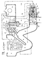
- a particular device allows the evacuation of the air inside the siphon during filling thereof and ensures the non-reintroduction of air throughout the duration of the siphonic suction.
- the bowl (I) extends downwards through the orifice (2) and a conduit (3) forming a siphon, with its culminating part (4), its descending branch (5) and the terminal part (6) which communicates with the downpipe (7).
- a valve (8) furnished with a peripheral seal (9) slides inside (6) to alternate between closed and open positions. Its travel is arranged so that at the start of its opening, the sliding takes place on a solid cylindrical part (6a).
- This valve (8) is, by a rod (IO), integral with a piston (II) sliding itself in a jack (12) constituted by an envelope (I3), a rear flange (14) and a front flange (I5).
- a rod (IO) integral with a piston (II) sliding itself in a jack (12) constituted by an envelope (I3), a rear flange (14) and a front flange (I5).
- This valve also comprises, on the jack side, a cylindrical tube (16) of the same diameter as it, the assembly being intended to slide inside the sheath (6), the extension on the jack side comprises a housed seal (17).
- the rod (10) has an internal recess (18).
- the piston (II) comprises, in addition to its peripheral seal (I9), a housed seal (20).
- the rear flange (14) has an orifice (2I) which is that of the water inlet actuating the closing of the valve.
- This flange (14) further carries in its center a fixed cylindrical tube (22) which penetrates inside the cylinder body (12) in the axis of sliding thereof and extends outside of the flange (14) by the conduit (23) which supplies the reservoir (24).
- the outside diameter of the tube (22) is arranged so as to slide in the recess (18), the seal (20) ensuring the The length of the tube (22) inside the cylinder body is established so that, in the end position corresponding to the complete closure of the valve, the piston (II) escapes of the tubing by providing a space (25) between the internal face (26) of the piston and the end (27) of the tubing (22).
- the actuator-valve assembly is hydraulically actuated by the piston distributor (28) and by means of its control rod (29).
- the conduits (30) and (31) starting from the distributor (28) to open into the body of the cylinder (I2) match respectively to the opening and closing circuits of the valve.
- the reservoir (24) the function of which is to store the water intended to reconstitute the water guard, is also of known type. It carries, in its upper part, an orifice (32) extending outwards by a conduit (33) which, parl'o rifice (34), feeds a ball box (35).
- This ball box (35) has, compared to those of the type. known, the originality of comprising in its middle part, a cage (36) inside which is placed a determined volume such as for example a sphere of very low density which is thus interposed between the upper light ball (38) and the lower heavy ball (39).
- the inside of the box is arranged to allow the free circulation of water.
- the sphere (37) is, in its upper part, in contact with the lower part of the ball (38).
- the level (40) corresponds to that of the natural floating of the sphere (37). We understand that, when this level rises, for example up to (40 a), the sphere (37) lifts and lifts in turn the ball (3 ⁇ ) which, by placing itself in the path of the jet, causes the balls to block on their respective sealing seats.
- the injection can be interrupted at the desired level.
- the reservoir (24) also has at its upper part another orifice (41) extending towards the outside by a conduit (42) opening into the upper part of the control distributor (28).
- the figure also shows in detail the particular device relating to the emptying of air into the siphon.
- An orifice (43) placed at the highest point (4) of the siphon communicates with a conduit (44) in ascending slope which opens, through the orifice (45) in the lower flange of a housing (46) which has a cover. upper (47) in which is arranged a bore (48) comprising a seal (49) for example O-ring.
- the housing (46) provides, in its internal part, a compartment (50) large enough to allow the free passage of air, inside which moves a rod (51) which slides in the bore (48 ) and carries, at its lower part, a valve (52) provided with a seal, for example made of rubber.
- the axis of the rod (51), placed in a substantially vertical position, corresponds to the axis of the orifice (45) so that the sliding of the rod (51) causes, alternately, through the valve (52), the opening and closing of the orifice (45).
- an orifice (53) extending outwardly by the con duct (54) which is in a downward slope and opens into the downward sheath.
- the rod (51) is extended outside the bore (48) by a rod (55) which is itself integral with the rod (29) for controlling the distributor (28), the assembly being arranged so that the rods (51) and (29) are parallel.
- the arrangement of the various elements with respect to each other is organized so that the level (40 a) is placed below that of the orifice (53) so that there can be no flow of liquid capable of interfere with the operation of the appliance.
- the water circulates through the orifice (32) and the conduit (33) towards the orifice (34) through which it enters the ball box (35). sprinkles the bowl which raises the level both in the bowl and in the siphon.
- valve (52) is placed on its seat of the orifice (45) preventing any possibility of rein air in the siphon.
- the valve opens causing a powerful siphonic suction which evacuates the effluents.
- the tubing (16) acts, during the entire closing phase of the valve ( ⁇ ) and sliding opening as a protective sheath preventing any possibility of contact between the polluted liquid located in front of the valve (8) and the rod ( No pollution can thus go back to the distributor and the water distribution network.
- This end portion (6) could for example be inclined downward in a position substantially parallel to the rising branch of the siphon.
- the terminal part of the siphon in which the valve slides is arranged horizontally and that its axis is perpendicular to the longitudinal median plane of the device.
- This arrangement offers the advantage, by a telescopic fitting of the sheath (6) on the end of the siphon, to be able to adjust by simple pivoting, the position of the descent sheath (7) so as to respond, with a single model of bowl, to all possible connection situations.
Landscapes
- Engineering & Computer Science (AREA)
- Aviation & Aerospace Engineering (AREA)
- Health & Medical Sciences (AREA)
- Life Sciences & Earth Sciences (AREA)
- Hydrology & Water Resources (AREA)
- Public Health (AREA)
- Water Supply & Treatment (AREA)
- Jet Pumps And Other Pumps (AREA)
Applications Claiming Priority (4)
| Application Number | Priority Date | Filing Date | Title |
|---|---|---|---|
| FR8215443A FR2532971B1 (fr) | 1982-09-13 | 1982-09-13 | Appareil de w. c. a clapet hydraulique incorpore dans la partie terminale du siphon |
| FR8215443 | 1982-09-13 | ||
| FR8313743 | 1983-08-23 | ||
| FR8313743A FR2551111B2 (fr) | 1983-08-23 | 1983-08-23 | Appareil de w.-c., a clapet hydraulique incorpore dans la partie terminale du siphon |
Publications (1)
| Publication Number | Publication Date |
|---|---|
| EP0119366A1 true EP0119366A1 (de) | 1984-09-26 |
Family
ID=26223065
Family Applications (1)
| Application Number | Title | Priority Date | Filing Date |
|---|---|---|---|
| EP83430030A Withdrawn EP0119366A1 (de) | 1982-09-13 | 1983-09-12 | Toilettenvorrichtung mit einer hydraulischen Klappe eingebaut im Endteil eines Siphons |
Country Status (3)
| Country | Link |
|---|---|
| EP (1) | EP0119366A1 (de) |
| AU (1) | AU1948983A (de) |
| WO (1) | WO1984001178A1 (de) |
Cited By (2)
| Publication number | Priority date | Publication date | Assignee | Title |
|---|---|---|---|---|
| AT403071B (de) * | 1996-04-30 | 1997-11-25 | Walter Dipl Ing Kuprian | Wasserklosett |
| FR2863635A1 (fr) * | 2003-12-10 | 2005-06-17 | Moise Piat | Appareil de wc a faible consommation d'eau |
Families Citing this family (2)
| Publication number | Priority date | Publication date | Assignee | Title |
|---|---|---|---|---|
| FR2551111B2 (fr) * | 1983-08-23 | 1986-03-14 | Piat Moise | Appareil de w.-c., a clapet hydraulique incorpore dans la partie terminale du siphon |
| US4687566A (en) * | 1985-03-06 | 1987-08-18 | Swiss Aluminium Ltd. | Protective collar for anode spade pin |
Citations (5)
| Publication number | Priority date | Publication date | Assignee | Title |
|---|---|---|---|---|
| GB191215705A (en) * | 1912-07-05 | 1913-07-07 | Arthur Goulding | Improvements in or relating to Flushing Apparatus for Water Closets and the like. |
| AU437147B2 (en) * | 1968-03-18 | 1973-06-22 | Squair Corporation Limited | Siphon valve |
| FR2227402A1 (en) * | 1973-04-27 | 1974-11-22 | Piat Moise | W.C. flushing system - series of button operated valves and reservoirs |
| US3965492A (en) * | 1974-08-12 | 1976-06-29 | Hendricks Victor P | Electric flushing toilet bowl |
| FR2455132A1 (fr) * | 1979-04-27 | 1980-11-21 | Piat Moise | Dispositif automatique de nettoyage et vidage de cuvette de w.-c. |
-
1983
- 1983-09-12 WO PCT/FR1983/000178 patent/WO1984001178A1/fr not_active Ceased
- 1983-09-12 EP EP83430030A patent/EP0119366A1/de not_active Withdrawn
- 1983-09-12 AU AU19489/83A patent/AU1948983A/en not_active Abandoned
Patent Citations (5)
| Publication number | Priority date | Publication date | Assignee | Title |
|---|---|---|---|---|
| GB191215705A (en) * | 1912-07-05 | 1913-07-07 | Arthur Goulding | Improvements in or relating to Flushing Apparatus for Water Closets and the like. |
| AU437147B2 (en) * | 1968-03-18 | 1973-06-22 | Squair Corporation Limited | Siphon valve |
| FR2227402A1 (en) * | 1973-04-27 | 1974-11-22 | Piat Moise | W.C. flushing system - series of button operated valves and reservoirs |
| US3965492A (en) * | 1974-08-12 | 1976-06-29 | Hendricks Victor P | Electric flushing toilet bowl |
| FR2455132A1 (fr) * | 1979-04-27 | 1980-11-21 | Piat Moise | Dispositif automatique de nettoyage et vidage de cuvette de w.-c. |
Cited By (2)
| Publication number | Priority date | Publication date | Assignee | Title |
|---|---|---|---|---|
| AT403071B (de) * | 1996-04-30 | 1997-11-25 | Walter Dipl Ing Kuprian | Wasserklosett |
| FR2863635A1 (fr) * | 2003-12-10 | 2005-06-17 | Moise Piat | Appareil de wc a faible consommation d'eau |
Also Published As
| Publication number | Publication date |
|---|---|
| AU1948983A (en) | 1984-04-04 |
| WO1984001178A1 (fr) | 1984-03-29 |
Similar Documents
| Publication | Publication Date | Title |
|---|---|---|
| FR2957098A1 (fr) | Detection de fuite sur robinet de chasse d'eau | |
| FR2662194A1 (fr) | Mecanisme de chasse interrompable, a ecoulement minimal assure. | |
| FR2549158A1 (fr) | Installation de pompage d'eau | |
| WO1984001178A1 (fr) | Appareil de w.c. a clapet hydraulique incorpore dans la partie terminale du siphon | |
| EP0177400A1 (de) | Schwimmende Behälterdecke eines Speichertanks insbesondere verwendet in einer Elektronuklearanlage | |
| EP0172778A2 (de) | Spülmechanismus vom Typ einer Kugelklappe | |
| FR2681891A1 (fr) | Perfectionnements aux dispositifs d'evacuation et de vidange rapide de liquide d'un reservoir de cuvette de w.c.. | |
| FR2657373A1 (fr) | Dispositif de curage d'un canal. | |
| FR2965835A1 (fr) | Installation comprenant un poste de transformation electrique et un systeme ameliore de separation des eaux pluviales et de l'huile de fuite | |
| FR2720424A1 (fr) | Dispositif de chasse d'eau automatique pour un réservoir de liquide et application à une fosse d'aisance. | |
| EP0740725A1 (de) | Anordnung zum füllen und entleeren eines toilettenspülkastens | |
| FR2665744A1 (fr) | Clapet pour la commande de l'ecoulement d'un liquide a partir d'un reservoir. | |
| FR2532971A1 (fr) | Appareil de w. c. a clapet hydraulique incorpore dans la partie terminale du siphon | |
| WO1997011235A1 (fr) | Appareil de w-c a siphon mobile | |
| EP2146012B1 (de) | Spülvorrichtung wobei eine gleichzeitige Einstellung von einem Schwimmer und einem Überlaufrohr möglich ist | |
| FR2740794A1 (fr) | Mecanisme de chasse d'eau | |
| FR2618297A1 (fr) | Dispositif a reserve de liquide pour l'alimentation automatique notamment pot pour plante | |
| EP2644285B1 (de) | Vorrichtung zum Ausspülen eines Beckens | |
| EP0178210A1 (de) | Schwimmende Behälterdecke eines Speichertanks insbesondere verwendet in einer Elektronuklearanlage | |
| EP2868819B1 (de) | Einheit für Toiletten mit einem Wasserspülmechanismus und einem Wassertank | |
| FR2678968A1 (fr) | Dispositif de chasse d'eau destine a equiper un reservoir pour en commander la vidange au moins partielle. | |
| FR2551111A2 (fr) | Appareil de w.-c., a clapet hydraulique incorpore dans la partie terminale du siphon | |
| BE650226A (de) | ||
| FR2717518A1 (fr) | Appareil de W.C. à faible consommation d'eau, à siphon pivotant. | |
| EP0223805B1 (de) | Wasserspüleinrichtung |
Legal Events
| Date | Code | Title | Description |
|---|---|---|---|
| PUAI | Public reference made under article 153(3) epc to a published international application that has entered the european phase |
Free format text: ORIGINAL CODE: 0009012 |
|
| 17P | Request for examination filed |
Effective date: 19831012 |
|
| AK | Designated contracting states |
Designated state(s): AT BE CH DE FR GB IT LI LU NL SE |
|
| 17Q | First examination report despatched |
Effective date: 19870326 |
|
| STAA | Information on the status of an ep patent application or granted ep patent |
Free format text: STATUS: THE APPLICATION IS DEEMED TO BE WITHDRAWN |
|
| 18D | Application deemed to be withdrawn |
Effective date: 19870806 |