EP2146012B1 - Spülvorrichtung wobei eine gleichzeitige Einstellung von einem Schwimmer und einem Überlaufrohr möglich ist - Google Patents
Spülvorrichtung wobei eine gleichzeitige Einstellung von einem Schwimmer und einem Überlaufrohr möglich ist Download PDFInfo
- Publication number
- EP2146012B1 EP2146012B1 EP09305636.4A EP09305636A EP2146012B1 EP 2146012 B1 EP2146012 B1 EP 2146012B1 EP 09305636 A EP09305636 A EP 09305636A EP 2146012 B1 EP2146012 B1 EP 2146012B1
- Authority
- EP
- European Patent Office
- Prior art keywords
- overflow tube
- float
- flushing device
- collar
- casing
- Prior art date
- Legal status (The legal status is an assumption and is not a legal conclusion. Google has not performed a legal analysis and makes no representation as to the accuracy of the status listed.)
- Active
Links
Images



Classifications
-
- E—FIXED CONSTRUCTIONS
- E03—WATER SUPPLY; SEWERAGE
- E03D—WATER-CLOSETS OR URINALS WITH FLUSHING DEVICES; FLUSHING VALVES THEREFOR
- E03D1/00—Water flushing devices with cisterns ; Setting up a range of flushing devices or water-closets; Combinations of several flushing devices
- E03D1/02—High-level flushing systems
- E03D1/14—Cisterns discharging variable quantities of water also cisterns with bell siphons in combination with flushing valves
- E03D1/142—Cisterns discharging variable quantities of water also cisterns with bell siphons in combination with flushing valves in cisterns with flushing valves
- E03D1/144—Cisterns discharging variable quantities of water also cisterns with bell siphons in combination with flushing valves in cisterns with flushing valves having a single flush outlet and an additional float for delaying the valve closure
-
- E—FIXED CONSTRUCTIONS
- E03—WATER SUPPLY; SEWERAGE
- E03D—WATER-CLOSETS OR URINALS WITH FLUSHING DEVICES; FLUSHING VALVES THEREFOR
- E03D1/00—Water flushing devices with cisterns ; Setting up a range of flushing devices or water-closets; Combinations of several flushing devices
- E03D1/30—Valves for high or low level cisterns; Their arrangement ; Flushing mechanisms in the cistern, optionally with provisions for a pre-or a post- flushing and for cutting off the flushing mechanism in case of leakage
- E03D1/34—Flushing valves for outlets; Arrangement of outlet valves
Definitions
- the present invention relates to a flush device with adjustable water reserve and in particular for a toilet bowl.
- the present invention also relates to a simplified method of setting a flushing device and this, in order to accurately empty a portion of the water present in a flush tank.
- the document DE 100 49 645 discloses a toilet flushing device comprising a valve body of a flow valve that can be lifted via a lower float or a top float during a complete flush or partial flushing respectively, the lower float being fixedly retained by a magnetic retaining force during the partial flush.
- This device also comprises a valve body holding device, integral therewith and arranged to rest or be above the upper float.
- the document EP 0 723 050 discloses a dual-flush flush device comprising an overflow tube, a lower float and a small flush upper flush, the upper float can abut against a cross.
- the document EP 1 674 623 discloses a flush double flush device according to the preamble of claim 1, comprising a overflow tube along which are arranged a lower flush of large flush and a small flush upper flush, setting the small flush float by means of grooves and guides which also serve to adjust the length of the overflow tube ( ⁇ 0036).
- the present invention aims to propose a new flushing device that avoids all or part of the aforementioned drawbacks.
- the subject of the invention is a flushing device according to claim 1.
- the flushing device has the advantage of facilitating the adjustment of the overflow tube and the small flush float. Indeed, the adjustment of the overflow tube defines at the same time the adjustment of the float.
- the small flush float is positioned vertically and has at its upper end a stop adapted to cooperate with the abutment surface of said overflow tube.
- said envelope has support means for said overflow tube.
- said casing has a rib capable of cooperating with two tabs arranged on said float, so that said float slides relative to the casing.
- the upper end of the upper portion of the overflow tube includes the flanges and the lower end of the lower portion is connected to the exhaust valve.
- the lower part of the overflow tube is guided in the envelope.
- the present invention also relates to a method of adjusting a flushing device according to the invention during the installation of said flush device in a water tank of a sanitary appliance according to claim 7.
- the length of the overflow tube is adjusted by screwing the upper part into the lower part of said overflow tube.
- a flush device 1 for insertion into a tank or a tank of sanitary water (not shown), such as a toilet bowl, is shown.
- a tank or a tank of sanitary water (not shown), such as a toilet bowl, is shown.
- the bottom of the tank or reservoir is drilled, in its center, a brutal discharge orifice 7 of water.
- a base 20 raises, above the discharge port 7, a casing 14, which include among others a tube 2 overflow to evacuate the overflow of water present in the tank, a large hunting float 24 and a small hunting float 9.
- This small hunting float 9 allows to evacuate a small portion of water for small hunts, while the action of the float large hunting 24 can empty a large portion of water for large hunts.
- These floats 24 and 9 evacuate a certain amount of water thanks in particular to their buoyancy and their positioning within said flush device 1.
- a third external float, called float valve, (not shown) allows a known way of refill the water tank after using a small hunt or large hunt.
- the envelope 14 of the flushing device 1 has a cylindrical shape of substantially square section.
- the upper end 15 of the envelope 14 is open so that the overflow tube 2 can project relative thereto, while its end lower 16 comprises a cylindrical sleeve 18 and thus having an internal cavity.
- This first sleeve 18 is arranged vertically.
- the height of the sleeve 18 is of sufficient length so that a discharge valve 26 formed mainly by a gasket 6, as will be seen below, can be retracted during the emptying in order to shelter from the flow of 'water.
- a damper 5 is substantially cylindrical in shape and also has an internal cavity. In addition, it is able to fit into the internal cavity of the sleeve 18. It has the particular function of creating a laminar flow of water during a hunt.
- Part of the upper end of the sleeve 18 is connected to a partition 17 in the form of a half-cylinder (not visible in the figures).
- This wall 17 serves to limit with the diametrically opposite wall of the casing 14, the chamber of the float large hunting 24.
- a radial wall 19 connects the sleeve 18 and the partition 17 and serves as "cover" to the sleeve 18.
- This cover just as the damper 5 and the seal 6 have an orifice in their center, so as to receive the lower end of the overflow tube 2. Moreover, it is this lower end of the overflow tube 2 which form with the seal 6, the discharge valve 26.
- the casing 14 is further positioned vertically within the water reservoir so as to be positioned in front of the discharge orifice 7.
- the casing 14 is provided with the base 20.
- the base 20 has a first portion 20a which is fixed for example by clipping on the sleeve 18. From this first portion 20a, the base 20 has a second vertical portion 20b which connects the first to a third portion 20c.
- the second part 20b in the form of three distributed feet, raises the envelope 14 and makes it possible to form a reception space between the bottom of the latter and the discharge orifice 7, in order to receive there, when a flush or not, the lower portion of the sleeve 18, the damper 5 and the seal 6.
- the third portion 20c rests on the bottom of the tank and has a shape so as to cross and embrace the contour of the discharge orifice 7, so that the envelope 14 is held in the water tank.
- This part 20c has a seat 20d at the discharge port 7 to receive the seal 6 of the discharge valve 26, the seal 6 perfectly matching the contours of the seat 20d.
- the casing 14 also has along its wall a vertical rib 13 capable of cooperating with the small hunting float 9, so that it is also free in translation relative to the casing 14.
- the flush device 1 also includes the overflow tube 2 as mentioned above.
- the overflow tube 2 comprises two parts: a lower part 4 and an upper part 3 movable relative to the lower part 4.
- the upper part 3 is indeed capable of sliding or screwing, as shown in the figures in the lower part 4, so that the overflow tube 2 is of adjustable length.
- the overflow pipe 2 is also held in place by means of the radial wall 19, the damper 5 and the gasket 6.
- the lower end of the lower part 4 carries the seal 6, so as to form the discharge valve 26, while the upper end of the upper part 3, that is to say the one not connected to the part bottom 4, includes an enlarged portion 8.
- This enlarged portion 8 defines a first flange 8a which can form a first abutment surface of the overflow tube 2.
- the enlarged portion 8 is surrounded by a ring 25.
- This ring 25 comprises, disposed at its lower end, also a flange, said second flange 25a, so as to also form a stop surface of the overflow tube 2.
- This ring 25 is further adapted to extend along the enlarged portion 8 of the overflow tube 2 to be positioned in the so-called short position, in which the flange 8a and the collar 25a are adjacent so as to both form the stop surface of the overflow tube 2 ( figure 8 ).
- the ring 25 can in a so-called long position, extend from the lower end of the enlarged portion 8, that is to say from the first collar 8a ( figure 7 ).
- This position can be obtained by sliding the ring 25 downwards and being guided by one or more rib / groove systems 27 ( Figures 7 and 8 ).
- the flange 25a serves as a stop surface for the overflow tube 2 in this long position. Indeed in this position, the flange 25a is lower than the flange 8a.
- the positioning of the abutment surface of the overflow tube 2 serves as means for adjusting both the overflow tube 2 and the small flush float 9. In particular, its adjustment allows the evacuation of more or less water during the small hunt.
- the discharge valve 26 is said to be closed when the seal 6 closes the orifice 7 and is said to be open when the orifice 7 is released during the lifting of the overflow tube which takes the seal 6 in its stroke.
- the seal 6 is flexible and removable.
- the seal 6 is also drilled in the middle, so as to allow the overflow tube 2 and in particular at the lower end of the lower portion 4 to protrude slightly relative to the seal 6. As already mentioned, this end of overflow tube 2 forms with gasket 6, exhaust valve 26.
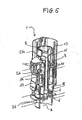
- valve 26 The opening or closing of said valve 26 is inter alia in a two-volume system, as shown in FIGS. Figures 1 to 6 either to the action of a small hunting float 9 positioned inside the casing 14, or to the action of a large flush float 24, for example rocking.
- FIGS. Figures 1 to 6 The operation of both systems are well known to those skilled in the art and will not be explained in detail in the present description.
- the small hunting float 9 is of elongated shape and is positioned vertically within the envelope 14, between one of the walls of the overflow tube 2, the inner wall of the casing 14, and the collar 8 , so as to guide said small hunting float 9.
- This small flotation float 9 also comprises two tabs 10 forming an internal notch capable of tying the rib 13 of the envelope 14. In this way the small flotation float 9 is guided and can slide along the rib 13.
- the small flotation float 9 has at its upper end a stop 11. This stop 11 is able to abut on the flanges 8a or 25a, so that the small flush float 9 cooperating with the tube too much 2 is able to maintain the discharge valve 26 temporarily open and release, therefore, the discharge port 7.
- the small hunting float 9 has a buoyancy that depends on the portion of water that the user wants to evacuate with each small hunt. For example, it can be sized to release 3L of water.
- This small hunting float 9 is indeed able to exert an Archimedean force on the flanges 8a or 25a of the enlarged portion 8 or the ring 25. This makes it possible to prevent for a short period of time, it is up to say the time to evacuate 3 L of water from the tank, closing the drain valve 26.
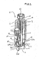
- the flushing device 1 is first installed in a tank containing no water.
- the casing 14 is arranged vertically, the small flush float 9, sized to evacuate 3 L of water, rests on the wall 19, the overflow tube 2, whose length n ' is not yet set, is inserted into the second sleeve 17 and the discharge valve 26 is in the closed position.
- the second step of the installation is to fill the water tank to the desired height.
- indexing marks are pre-written on the inner wall of the tank, so as to guide more easily the installer of the flush device 1.
- the installer fills the tank, so that it contains 6 to 7.5 L of water corresponding to the amount of water needed for a large hunt.
- the small flotation float 9 is carried by the water and back up to be in contact with the flange 8a of the enlarged portion 8 of the overflow tube 2 or the flange 25a of the ring 25 according to whether it is arranged in the short position or in the long position.
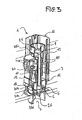
- the next step ( figure 3 ) is to adjust the length of the overflow tube 2. For this, is slid and then fixed, or simply screwed the upper part 3 of the overflow tube 2 in its lower part 4, so that the flanges 8a , 25a are in contact with the surface of the water present in the tank.
- the small hunting float 9, pushed by the overflow tube 2 is positioned, so as to evacuate a small flush volume. If the setting corresponds to a short position of the ring 25, the small flush float 9 is set to subsequently evacuate about 3 L of water. If the adjustment corresponds to a long position of the ring 25, the small flush float 9 is set to subsequently evacuate a greater quantity of water, approximately 3.25 to 4 L.
- valve 26 when the installer or a user subsequently activates the small flush, the valve 26 will lift thereby releasing some of the water in the tank. During this manipulation, the valve 26 will lift, via a mechanism known to those skilled in the art, and remain in the open position thanks to the action of the small hunting float 9 on the collar or flanges 8a and / or 25a of the overflow tube 2.
- the small flush float 9 will indeed exert an Archimedean force on the overflow tube 2 so that the discharge valve 26 remains open so as to release the amount of water desired small hunt.
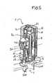
- the float valve will fill the tank, so that it has enough water for a small or large hunt ( figure 6 ).
- the present device has the advantage of facilitating the adjustment of the overflow tube 2 and small hunting flush 9 small flush as shown in the embodiment as described. The adjustment of these two elements is now done simultaneously and accurately.
Landscapes
- Health & Medical Sciences (AREA)
- Life Sciences & Earth Sciences (AREA)
- Engineering & Computer Science (AREA)
- Hydrology & Water Resources (AREA)
- Public Health (AREA)
- Water Supply & Treatment (AREA)
- Sanitary Device For Flush Toilet (AREA)
- Float Valves (AREA)
Claims (8)
- Spülvorrichtung (1), umfassend ein Gehäuse (14), ein Überlaufrohr (2), ein Abflussventil (26), fähig eine Wasserabflussöffnung (7) in einer Verschlussposition zu verschließen und die Öffnung (7) in einer Öffnungsposition freizugeben, einen Sparspülungsschwimmer (9), dessen Position einstellbar ist mit Bezug auf das Gehäuse (14), wobei der Sparspülungsschwimmer (9) dazu bestimmt ist das Abflussventil (26) in Öffnungsposition zu halten bis das ein gewünschtes Volumen an Wasser abgeflossen ist, wobei das Überlaufrohr (2) einen oberen Abschnitt (3) und einen unteren Abschnitt (4) umfasst, wobei die Position des oberen Abschnittes (3) einstellbar ist mit Bezug auf den unteren Abschnitt (4) vermittels Gleitens des oberen Abschnittes mit Bezug auf den unteren Abschnitt, derart, dass die Länge des Überlaufrohres (2) eingestellt ist/wird während der Installation der Spülvorrichtung (1), und wobei das Überlaufrohr (2) eine Anlagefläche umfasst, die die Einstellposition des Sparspülungsschwimmers (9) während der Installation der Vorrichtung definiert, derart, dass die Einstellung der Länge des Überlaufrohres (2) und die Einstellung der Position des Sparspülungsschwimmers (9) gleichzeitig während der Installation erfolgen, dadurch gekennzeichnet, dass das Überlaufrohr (2) einen ersten Kragen (8a), ausgebildet an seinem oberen Ende umfasst, wobei das Überlaufrohr ferner auf dem Niveau des ersten Kragens einen Ring (25) umfasst, an welchem ein zweiter Kragen (25a) angeordnet ist, wobei der Ring (25) fähig ist zwischen zwei Positionen mit Bezug auf den ersten Kragen (8a) zu gleiten, wobei der erste Kragen (8a) eine erste Fläche der Anlagefläche des Überlaufrohres (2) bildet und der zweite Kragen (25a) ebenfalls eine Fläche der Anlagefläche des Überlaufrohres (2) bildet.
- Spülvorrichtung nach Anspruch 1, bei welcher der Sparspülungsschwimmer (9) vertikal angeordnet ist und an seinem oberen Ende einen Anschlag (11) aufweist, fähig zum Wechselwirken mit der Anlagefläche des Überlaufrohres (2).
- Spülvorrichtung nach einem der Ansprüche 1 bis 2, bei welcher das Gehäuse (14) Stützmittel (5, 6, 18, 19) des Überlaufrohres (2) aufweist.
- Spülvorrichtung nach einem der vorangegangenen Ansprüche, bei welcher das Gehäuse (14) eine Rippe (13) aufweist, fähig zur Wechselwirkung mit zwei Laschen (10), am Sparspülungsschwimmer (9) ausgebildet, so dass der Sparspülungsschwimmer (9) mit Bezug auf das Gehäuse (14) gleitet.
- Spülvorrichtung nach einem der vorangegangenen Ansprüche, bei welcher das obere Ende des oberen Abschnittes (3) des Überlaufrohres (2) den Kragen (8a) enthält und das untere Ende des unteren Abschnittes (4) mit dem Abflussventil (26) verbunden ist.
- Spülvorrichtung nach einem der vorangegangenen Ansprüche, bei welcher der untere Abschnitt (4) des Überlaufrohres (2) durch das Gehäuse (14) geführt ist/wird.
- Verfahren zum Einstellen einer Spülvorrichtung (1) gemäß einem der Ansprüche 1 bis 6 während der Installation der Spülvorrichtung (1) in einem Wasserreservoir eines Sanitärgerätes, dadurch gekennzeichnet, dass das Verfahren die Schritte umfasst:- Positionieren des Ringes (25) in einer der zwei Positionen mit Bezug auf den ersten Kragen (8a) um die Position der Anlagefläche des Überlaufrohres (2) zu definieren,- Befüllen des Wasserreservoirs bis zu einer gewünschten Höhe, so dass der Schwimmer (9) ansteigt unter die Anlagefläche des Überlaufrohres (2),- Veranlassen einer Gleitbewegung des oberen Abschnittes (3) des Überlaufrohres (2) in den unteren Abschnitt (4) um die Länge des Überlaufrohres (2) einzustellen, derart, dass dessen Anlagefläche in Berührung steht/gelangt mit der in dem Reservoir bestehenden Wasseroberfläche.
- Verfahren nach Anspruch 7, bei welchem die Länge des Überlaufrohres (2) eingestellt ist/wird indem der obere Abschnitt (3) in den unteren Abschnitt (4) des Überlaufrohres (2) geschraubt ist/wird.
Applications Claiming Priority (1)
| Application Number | Priority Date | Filing Date | Title |
|---|---|---|---|
| FR0804053A FR2933996B1 (fr) | 2008-07-16 | 2008-07-16 | Dispositif de chasse d'eau permettant un reglage simultane d'un flotteur et d'un tube de trop plein |
Publications (2)
| Publication Number | Publication Date |
|---|---|
| EP2146012A1 EP2146012A1 (de) | 2010-01-20 |
| EP2146012B1 true EP2146012B1 (de) | 2016-01-06 |
Family
ID=40409729
Family Applications (1)
| Application Number | Title | Priority Date | Filing Date |
|---|---|---|---|
| EP09305636.4A Active EP2146012B1 (de) | 2008-07-16 | 2009-07-01 | Spülvorrichtung wobei eine gleichzeitige Einstellung von einem Schwimmer und einem Überlaufrohr möglich ist |
Country Status (4)
| Country | Link |
|---|---|
| EP (1) | EP2146012B1 (de) |
| ES (1) | ES2566967T3 (de) |
| FR (1) | FR2933996B1 (de) |
| PL (1) | PL2146012T3 (de) |
Cited By (1)
| Publication number | Priority date | Publication date | Assignee | Title |
|---|---|---|---|---|
| WO2019130260A1 (en) | 2017-12-28 | 2019-07-04 | Lixil International Pte. Ltd. | Height-adjustable upright tube-cage unit |
Family Cites Families (5)
| Publication number | Priority date | Publication date | Assignee | Title |
|---|---|---|---|---|
| FR2676480B1 (fr) * | 1991-05-16 | 1993-08-20 | Tolbert Timothy | Dispositif d'evacuation pour reservoir, a deversement variable. |
| DE19501355C2 (de) * | 1995-01-18 | 1997-07-10 | Friatec Keramik Kunststoff | Ablaufarmatur für einen Spülkasten |
| DE10049645C1 (de) * | 2000-10-05 | 2002-01-03 | Georg Fischer Schwab Gmbh | Ablaufarmatur für einen WC-Spülkasten |
| ITMI20042510A1 (it) * | 2004-12-24 | 2005-03-24 | Oliveira & Irmao Sa | Gruppo valvola di scarico di una cassetta di risciacquo |
| DE202006016050U1 (de) * | 2006-10-17 | 2008-02-28 | Viega Gmbh & Co. Kg | Zwei-Mengen-Ablaufventil für einen Spülkasten |
-
2008
- 2008-07-16 FR FR0804053A patent/FR2933996B1/fr active Active
-
2009
- 2009-07-01 ES ES09305636.4T patent/ES2566967T3/es active Active
- 2009-07-01 EP EP09305636.4A patent/EP2146012B1/de active Active
- 2009-07-01 PL PL09305636.4T patent/PL2146012T3/pl unknown
Cited By (2)
| Publication number | Priority date | Publication date | Assignee | Title |
|---|---|---|---|---|
| WO2019130260A1 (en) | 2017-12-28 | 2019-07-04 | Lixil International Pte. Ltd. | Height-adjustable upright tube-cage unit |
| DE102017131401A1 (de) | 2017-12-28 | 2019-07-04 | Lixil International Pte. Ltd. | Höhenverstellbare standrohr-käfig-einheit |
Also Published As
| Publication number | Publication date |
|---|---|
| FR2933996B1 (fr) | 2011-10-14 |
| EP2146012A1 (de) | 2010-01-20 |
| ES2566967T3 (es) | 2016-04-18 |
| FR2933996A1 (fr) | 2010-01-22 |
| PL2146012T3 (pl) | 2016-09-30 |
Similar Documents
| Publication | Publication Date | Title |
|---|---|---|
| EP2542727B1 (de) | Leckerkennung bei einem spülblock | |
| EP3194670B1 (de) | Vorrichtung für toiletten | |
| FR2788258A1 (fr) | Limiteur de remplissage pour cuve de stockage d'un liquide | |
| FR2662194A1 (fr) | Mecanisme de chasse interrompable, a ecoulement minimal assure. | |
| FR2672322A1 (fr) | Dispositif de chasse d'eau permettant de delivrer differents volumes d'eau predetermines. | |
| FR2680192A1 (fr) | Mecanisme de chasse a double commande, permettant d'operer, selectivement, la vidange complete ou partielle du reservoir. | |
| EP0522218A1 (de) | Druckknopfspülmechanismus mit eintauchbarem Körper | |
| FR2676480A1 (fr) | Dispositif d'evacuation pour reservoir, a deversement variable. | |
| EP2146012A1 (de) | Spülvorrichtung wobei eine gleichzeitige Einstellung von einem Schwimmer und einem Überlaufrohr möglich ist | |
| WO2007003772A1 (fr) | Dispositif distributeur d'un produit nettoyant pour chasse d'eau | |
| FR2965835A1 (fr) | Installation comprenant un poste de transformation electrique et un systeme ameliore de separation des eaux pluviales et de l'huile de fuite | |
| WO1997017503A1 (fr) | Dispositif a double commande de chasse de reservoir d'eau | |
| WO2012063004A1 (fr) | Dispositif pour la distribution d'un produit desodorisant pour un dispositif de chasse d'eau de w.c. | |
| EP0209477B1 (de) | Spülvorrichtung mit schwimmender Heberglocke für Spülkasten | |
| EP0172778A2 (de) | Spülmechanismus vom Typ einer Kugelklappe | |
| EP2868819B1 (de) | Einheit für Toiletten mit einem Wasserspülmechanismus und einem Wassertank | |
| FR2942815A1 (fr) | Chasse d'eau a ouverture retardee | |
| FR2667892A1 (fr) | Mecanisme de chasse d'eau pour toilettes. | |
| FR2494464A1 (fr) | Dispositif pour le remplissage d'un reservoir de chasse d'eau | |
| EP0884423A2 (de) | Spülkastenwassersparvorrichtung | |
| FR2473586A1 (fr) | Dispositif pour l'evacuation de l'eau d'un reservoir de chasse d'eau de water-closet notamment, sous deux volumes differents | |
| EP1396668B1 (de) | Automatische Absperrvorrichtung eines Durchflusskanals | |
| FR2576620A1 (fr) | Dispositif de chasse d'eau en particulier pour cuvette de toilette. | |
| EP0119366A1 (de) | Toilettenvorrichtung mit einer hydraulischen Klappe eingebaut im Endteil eines Siphons | |
| WO2025109460A1 (fr) | Système de chasse d'eau silencieux muni d'un siphon |
Legal Events
| Date | Code | Title | Description |
|---|---|---|---|
| PUAI | Public reference made under article 153(3) epc to a published international application that has entered the european phase |
Free format text: ORIGINAL CODE: 0009012 |
|
| AK | Designated contracting states |
Kind code of ref document: A1 Designated state(s): AT BE BG CH CY CZ DE DK EE ES FI FR GB GR HR HU IE IS IT LI LT LU LV MC MK MT NL NO PL PT RO SE SI SK SM TR |
|
| 17P | Request for examination filed |
Effective date: 20100617 |
|
| 17Q | First examination report despatched |
Effective date: 20130612 |
|
| RAP1 | Party data changed (applicant data changed or rights of an application transferred) |
Owner name: RACCORDS ET PLASTIQUES NICOLL |
|
| GRAP | Despatch of communication of intention to grant a patent |
Free format text: ORIGINAL CODE: EPIDOSNIGR1 |
|
| INTG | Intention to grant announced |
Effective date: 20150701 |
|
| GRAS | Grant fee paid |
Free format text: ORIGINAL CODE: EPIDOSNIGR3 |
|
| GRAA | (expected) grant |
Free format text: ORIGINAL CODE: 0009210 |
|
| AK | Designated contracting states |
Kind code of ref document: B1 Designated state(s): AT BE BG CH CY CZ DE DK EE ES FI FR GB GR HR HU IE IS IT LI LT LU LV MC MK MT NL NO PL PT RO SE SI SK SM TR |
|
| REG | Reference to a national code |
Ref country code: GB Ref legal event code: FG4D Free format text: NOT ENGLISH |
|
| REG | Reference to a national code |
Ref country code: CH Ref legal event code: EP |
|
| REG | Reference to a national code |
Ref country code: IE Ref legal event code: FG4D Free format text: LANGUAGE OF EP DOCUMENT: FRENCH |
|
| REG | Reference to a national code |
Ref country code: AT Ref legal event code: REF Ref document number: 768989 Country of ref document: AT Kind code of ref document: T Effective date: 20160215 |
|
| REG | Reference to a national code |
Ref country code: DE Ref legal event code: R096 Ref document number: 602009035533 Country of ref document: DE |
|
| REG | Reference to a national code |
Ref country code: ES Ref legal event code: FG2A Ref document number: 2566967 Country of ref document: ES Kind code of ref document: T3 Effective date: 20160418 |
|
| REG | Reference to a national code |
Ref country code: LT Ref legal event code: MG4D |
|
| REG | Reference to a national code |
Ref country code: NL Ref legal event code: MP Effective date: 20160106 |
|
| REG | Reference to a national code |
Ref country code: AT Ref legal event code: MK05 Ref document number: 768989 Country of ref document: AT Kind code of ref document: T Effective date: 20160106 |
|
| PG25 | Lapsed in a contracting state [announced via postgrant information from national office to epo] |
Ref country code: NL Free format text: LAPSE BECAUSE OF FAILURE TO SUBMIT A TRANSLATION OF THE DESCRIPTION OR TO PAY THE FEE WITHIN THE PRESCRIBED TIME-LIMIT Effective date: 20160106 |
|
| REG | Reference to a national code |
Ref country code: FR Ref legal event code: PLFP Year of fee payment: 8 |
|
| PG25 | Lapsed in a contracting state [announced via postgrant information from national office to epo] |
Ref country code: GR Free format text: LAPSE BECAUSE OF FAILURE TO SUBMIT A TRANSLATION OF THE DESCRIPTION OR TO PAY THE FEE WITHIN THE PRESCRIBED TIME-LIMIT Effective date: 20160407 Ref country code: IT Free format text: LAPSE BECAUSE OF FAILURE TO SUBMIT A TRANSLATION OF THE DESCRIPTION OR TO PAY THE FEE WITHIN THE PRESCRIBED TIME-LIMIT Effective date: 20160106 Ref country code: FI Free format text: LAPSE BECAUSE OF FAILURE TO SUBMIT A TRANSLATION OF THE DESCRIPTION OR TO PAY THE FEE WITHIN THE PRESCRIBED TIME-LIMIT Effective date: 20160106 Ref country code: HR Free format text: LAPSE BECAUSE OF FAILURE TO SUBMIT A TRANSLATION OF THE DESCRIPTION OR TO PAY THE FEE WITHIN THE PRESCRIBED TIME-LIMIT Effective date: 20160106 Ref country code: NO Free format text: LAPSE BECAUSE OF FAILURE TO SUBMIT A TRANSLATION OF THE DESCRIPTION OR TO PAY THE FEE WITHIN THE PRESCRIBED TIME-LIMIT Effective date: 20160406 |
|
| PG25 | Lapsed in a contracting state [announced via postgrant information from national office to epo] |
Ref country code: SE Free format text: LAPSE BECAUSE OF FAILURE TO SUBMIT A TRANSLATION OF THE DESCRIPTION OR TO PAY THE FEE WITHIN THE PRESCRIBED TIME-LIMIT Effective date: 20160106 Ref country code: LV Free format text: LAPSE BECAUSE OF FAILURE TO SUBMIT A TRANSLATION OF THE DESCRIPTION OR TO PAY THE FEE WITHIN THE PRESCRIBED TIME-LIMIT Effective date: 20160106 Ref country code: PT Free format text: LAPSE BECAUSE OF FAILURE TO SUBMIT A TRANSLATION OF THE DESCRIPTION OR TO PAY THE FEE WITHIN THE PRESCRIBED TIME-LIMIT Effective date: 20160506 Ref country code: LT Free format text: LAPSE BECAUSE OF FAILURE TO SUBMIT A TRANSLATION OF THE DESCRIPTION OR TO PAY THE FEE WITHIN THE PRESCRIBED TIME-LIMIT Effective date: 20160106 Ref country code: AT Free format text: LAPSE BECAUSE OF FAILURE TO SUBMIT A TRANSLATION OF THE DESCRIPTION OR TO PAY THE FEE WITHIN THE PRESCRIBED TIME-LIMIT Effective date: 20160106 Ref country code: IS Free format text: LAPSE BECAUSE OF FAILURE TO SUBMIT A TRANSLATION OF THE DESCRIPTION OR TO PAY THE FEE WITHIN THE PRESCRIBED TIME-LIMIT Effective date: 20160506 |
|
| REG | Reference to a national code |
Ref country code: DE Ref legal event code: R097 Ref document number: 602009035533 Country of ref document: DE |
|
| PG25 | Lapsed in a contracting state [announced via postgrant information from national office to epo] |
Ref country code: DK Free format text: LAPSE BECAUSE OF FAILURE TO SUBMIT A TRANSLATION OF THE DESCRIPTION OR TO PAY THE FEE WITHIN THE PRESCRIBED TIME-LIMIT Effective date: 20160106 Ref country code: EE Free format text: LAPSE BECAUSE OF FAILURE TO SUBMIT A TRANSLATION OF THE DESCRIPTION OR TO PAY THE FEE WITHIN THE PRESCRIBED TIME-LIMIT Effective date: 20160106 |
|
| PLBE | No opposition filed within time limit |
Free format text: ORIGINAL CODE: 0009261 |
|
| STAA | Information on the status of an ep patent application or granted ep patent |
Free format text: STATUS: NO OPPOSITION FILED WITHIN TIME LIMIT |
|
| PG25 | Lapsed in a contracting state [announced via postgrant information from national office to epo] |
Ref country code: RO Free format text: LAPSE BECAUSE OF FAILURE TO SUBMIT A TRANSLATION OF THE DESCRIPTION OR TO PAY THE FEE WITHIN THE PRESCRIBED TIME-LIMIT Effective date: 20160106 Ref country code: CZ Free format text: LAPSE BECAUSE OF FAILURE TO SUBMIT A TRANSLATION OF THE DESCRIPTION OR TO PAY THE FEE WITHIN THE PRESCRIBED TIME-LIMIT Effective date: 20160106 Ref country code: SM Free format text: LAPSE BECAUSE OF FAILURE TO SUBMIT A TRANSLATION OF THE DESCRIPTION OR TO PAY THE FEE WITHIN THE PRESCRIBED TIME-LIMIT Effective date: 20160106 Ref country code: SK Free format text: LAPSE BECAUSE OF FAILURE TO SUBMIT A TRANSLATION OF THE DESCRIPTION OR TO PAY THE FEE WITHIN THE PRESCRIBED TIME-LIMIT Effective date: 20160106 |
|
| 26N | No opposition filed |
Effective date: 20161007 |
|
| PG25 | Lapsed in a contracting state [announced via postgrant information from national office to epo] |
Ref country code: BE Free format text: LAPSE BECAUSE OF NON-PAYMENT OF DUE FEES Effective date: 20160731 |
|
| PG25 | Lapsed in a contracting state [announced via postgrant information from national office to epo] |
Ref country code: SI Free format text: LAPSE BECAUSE OF FAILURE TO SUBMIT A TRANSLATION OF THE DESCRIPTION OR TO PAY THE FEE WITHIN THE PRESCRIBED TIME-LIMIT Effective date: 20160106 Ref country code: BG Free format text: LAPSE BECAUSE OF FAILURE TO SUBMIT A TRANSLATION OF THE DESCRIPTION OR TO PAY THE FEE WITHIN THE PRESCRIBED TIME-LIMIT Effective date: 20160406 |
|
| REG | Reference to a national code |
Ref country code: CH Ref legal event code: PL |
|
| PG25 | Lapsed in a contracting state [announced via postgrant information from national office to epo] |
Ref country code: MC Free format text: LAPSE BECAUSE OF FAILURE TO SUBMIT A TRANSLATION OF THE DESCRIPTION OR TO PAY THE FEE WITHIN THE PRESCRIBED TIME-LIMIT Effective date: 20160106 |
|
| PG25 | Lapsed in a contracting state [announced via postgrant information from national office to epo] |
Ref country code: CH Free format text: LAPSE BECAUSE OF NON-PAYMENT OF DUE FEES Effective date: 20160731 Ref country code: LI Free format text: LAPSE BECAUSE OF NON-PAYMENT OF DUE FEES Effective date: 20160731 |
|
| REG | Reference to a national code |
Ref country code: IE Ref legal event code: MM4A |
|
| REG | Reference to a national code |
Ref country code: FR Ref legal event code: PLFP Year of fee payment: 9 |
|
| PG25 | Lapsed in a contracting state [announced via postgrant information from national office to epo] |
Ref country code: IE Free format text: LAPSE BECAUSE OF NON-PAYMENT OF DUE FEES Effective date: 20160701 |
|
| PG25 | Lapsed in a contracting state [announced via postgrant information from national office to epo] |
Ref country code: LU Free format text: LAPSE BECAUSE OF NON-PAYMENT OF DUE FEES Effective date: 20160701 |
|
| PG25 | Lapsed in a contracting state [announced via postgrant information from national office to epo] |
Ref country code: HU Free format text: LAPSE BECAUSE OF FAILURE TO SUBMIT A TRANSLATION OF THE DESCRIPTION OR TO PAY THE FEE WITHIN THE PRESCRIBED TIME-LIMIT; INVALID AB INITIO Effective date: 20090701 Ref country code: CY Free format text: LAPSE BECAUSE OF FAILURE TO SUBMIT A TRANSLATION OF THE DESCRIPTION OR TO PAY THE FEE WITHIN THE PRESCRIBED TIME-LIMIT Effective date: 20160106 |
|
| PG25 | Lapsed in a contracting state [announced via postgrant information from national office to epo] |
Ref country code: MT Free format text: LAPSE BECAUSE OF FAILURE TO SUBMIT A TRANSLATION OF THE DESCRIPTION OR TO PAY THE FEE WITHIN THE PRESCRIBED TIME-LIMIT Effective date: 20160106 Ref country code: MK Free format text: LAPSE BECAUSE OF FAILURE TO SUBMIT A TRANSLATION OF THE DESCRIPTION OR TO PAY THE FEE WITHIN THE PRESCRIBED TIME-LIMIT Effective date: 20160106 |
|
| REG | Reference to a national code |
Ref country code: FR Ref legal event code: PLFP Year of fee payment: 10 |
|
| REG | Reference to a national code |
Ref country code: DE Ref legal event code: R082 Ref document number: 602009035533 Country of ref document: DE Representative=s name: SONNENBERG HARRISON PARTNERSCHAFT MBB PATENT- , DE |
|
| P01 | Opt-out of the competence of the unified patent court (upc) registered |
Effective date: 20230512 |
|
| PGFP | Annual fee paid to national office [announced via postgrant information from national office to epo] |
Ref country code: GB Payment date: 20230724 Year of fee payment: 15 |
|
| PGFP | Annual fee paid to national office [announced via postgrant information from national office to epo] |
Ref country code: DE Payment date: 20230720 Year of fee payment: 15 |
|
| REG | Reference to a national code |
Ref country code: DE Ref legal event code: R119 Ref document number: 602009035533 Country of ref document: DE |
|
| GBPC | Gb: european patent ceased through non-payment of renewal fee |
Effective date: 20240701 |
|
| PG25 | Lapsed in a contracting state [announced via postgrant information from national office to epo] |
Ref country code: DE Free format text: LAPSE BECAUSE OF NON-PAYMENT OF DUE FEES Effective date: 20250201 |
|
| PG25 | Lapsed in a contracting state [announced via postgrant information from national office to epo] |
Ref country code: GB Free format text: LAPSE BECAUSE OF NON-PAYMENT OF DUE FEES Effective date: 20240701 |
|
| PGFP | Annual fee paid to national office [announced via postgrant information from national office to epo] |
Ref country code: PL Payment date: 20250627 Year of fee payment: 17 |
|
| PGFP | Annual fee paid to national office [announced via postgrant information from national office to epo] |
Ref country code: ES Payment date: 20250819 Year of fee payment: 17 |
|
| PGFP | Annual fee paid to national office [announced via postgrant information from national office to epo] |
Ref country code: FR Payment date: 20250723 Year of fee payment: 17 |
|
| PGFP | Annual fee paid to national office [announced via postgrant information from national office to epo] |
Ref country code: TR Payment date: 20260625 Year of fee payment: 18 |