EP0119614B2 - Fibroscope - Google Patents
Fibroscope Download PDFInfo
- Publication number
- EP0119614B2 EP0119614B2 EP19840102942 EP84102942A EP0119614B2 EP 0119614 B2 EP0119614 B2 EP 0119614B2 EP 19840102942 EP19840102942 EP 19840102942 EP 84102942 A EP84102942 A EP 84102942A EP 0119614 B2 EP0119614 B2 EP 0119614B2
- Authority
- EP
- European Patent Office
- Prior art keywords
- fiberscope
- fiber bundle
- cover tube
- wall
- image
- Prior art date
- Legal status (The legal status is an assumption and is not a legal conclusion. Google has not performed a legal analysis and makes no representation as to the accuracy of the status listed.)
- Expired
Links
- 239000000835 fiber Substances 0.000 claims description 80
- 239000007788 liquid Substances 0.000 claims description 38
- 125000006850 spacer group Chemical group 0.000 claims description 24
- 239000013307 optical fiber Substances 0.000 claims description 14
- 239000002504 physiological saline solution Substances 0.000 claims description 13
- 239000000853 adhesive Substances 0.000 claims description 6
- 230000001070 adhesive effect Effects 0.000 claims description 6
- 239000007924 injection Substances 0.000 claims description 4
- 238000002347 injection Methods 0.000 claims description 4
- 239000000463 material Substances 0.000 claims description 3
- 230000003287 optical effect Effects 0.000 claims description 3
- 238000007789 sealing Methods 0.000 claims description 3
- 239000004033 plastic Substances 0.000 claims description 2
- 229920003023 plastic Polymers 0.000 claims description 2
- XLYOFNOQVPJJNP-UHFFFAOYSA-N water Substances O XLYOFNOQVPJJNP-UHFFFAOYSA-N 0.000 claims description 2
- 230000000541 pulsatile effect Effects 0.000 claims 1
- 230000010349 pulsation Effects 0.000 claims 1
- 230000001360 synchronised effect Effects 0.000 claims 1
- 238000010586 diagram Methods 0.000 description 13
- 229920005989 resin Polymers 0.000 description 12
- 239000011347 resin Substances 0.000 description 12
- 238000000034 method Methods 0.000 description 10
- 210000004204 blood vessel Anatomy 0.000 description 9
- 238000004519 manufacturing process Methods 0.000 description 9
- FAPWRFPIFSIZLT-UHFFFAOYSA-M Sodium chloride Chemical compound [Na+].[Cl-] FAPWRFPIFSIZLT-UHFFFAOYSA-M 0.000 description 8
- 239000008280 blood Substances 0.000 description 5
- 210000004369 blood Anatomy 0.000 description 5
- 230000000694 effects Effects 0.000 description 5
- 238000000465 moulding Methods 0.000 description 5
- XUIMIQQOPSSXEZ-UHFFFAOYSA-N Silicon Chemical compound [Si] XUIMIQQOPSSXEZ-UHFFFAOYSA-N 0.000 description 4
- 238000011010 flushing procedure Methods 0.000 description 4
- 230000035939 shock Effects 0.000 description 4
- 229910052710 silicon Inorganic materials 0.000 description 4
- 239000010703 silicon Substances 0.000 description 4
- 230000036772 blood pressure Effects 0.000 description 3
- 239000003822 epoxy resin Substances 0.000 description 3
- 229920000647 polyepoxide Polymers 0.000 description 3
- RSWGJHLUYNHPMX-UHFFFAOYSA-N Abietic-Saeure Natural products C12CCC(C(C)C)=CC2=CCC2C1(C)CCCC2(C)C(O)=O RSWGJHLUYNHPMX-UHFFFAOYSA-N 0.000 description 2
- KHPCPRHQVVSZAH-HUOMCSJISA-N Rosin Natural products O(C/C=C/c1ccccc1)[C@H]1[C@H](O)[C@@H](O)[C@@H](O)[C@@H](CO)O1 KHPCPRHQVVSZAH-HUOMCSJISA-N 0.000 description 2
- BZHJMEDXRYGGRV-UHFFFAOYSA-N Vinyl chloride Chemical compound ClC=C BZHJMEDXRYGGRV-UHFFFAOYSA-N 0.000 description 2
- 230000017531 blood circulation Effects 0.000 description 2
- 238000005266 casting Methods 0.000 description 2
- 239000011248 coating agent Substances 0.000 description 2
- 238000000576 coating method Methods 0.000 description 2
- 239000010779 crude oil Substances 0.000 description 2
- 239000012530 fluid Substances 0.000 description 2
- 238000003780 insertion Methods 0.000 description 2
- 230000037431 insertion Effects 0.000 description 2
- 229910052751 metal Inorganic materials 0.000 description 2
- 239000002184 metal Substances 0.000 description 2
- 230000002093 peripheral effect Effects 0.000 description 2
- 239000000243 solution Substances 0.000 description 2
- KHPCPRHQVVSZAH-UHFFFAOYSA-N trans-cinnamyl beta-D-glucopyranoside Natural products OC1C(O)C(O)C(CO)OC1OCC=CC1=CC=CC=C1 KHPCPRHQVVSZAH-UHFFFAOYSA-N 0.000 description 2
- 239000004593 Epoxy Substances 0.000 description 1
- 229910052782 aluminium Inorganic materials 0.000 description 1
- XAGFODPZIPBFFR-UHFFFAOYSA-N aluminium Chemical compound [Al] XAGFODPZIPBFFR-UHFFFAOYSA-N 0.000 description 1
- 230000015572 biosynthetic process Effects 0.000 description 1
- 238000010276 construction Methods 0.000 description 1
- 230000008878 coupling Effects 0.000 description 1
- 238000010168 coupling process Methods 0.000 description 1
- 238000005859 coupling reaction Methods 0.000 description 1
- 230000007423 decrease Effects 0.000 description 1
- 238000003745 diagnosis Methods 0.000 description 1
- 238000007599 discharging Methods 0.000 description 1
- 238000006073 displacement reaction Methods 0.000 description 1
- 229920006332 epoxy adhesive Polymers 0.000 description 1
- 239000002654 heat shrinkable material Substances 0.000 description 1
- 238000005304 joining Methods 0.000 description 1
- 238000003754 machining Methods 0.000 description 1
- 229920013716 polyethylene resin Polymers 0.000 description 1
- 239000011780 sodium chloride Substances 0.000 description 1
- 239000000126 substance Substances 0.000 description 1
- 238000011144 upstream manufacturing Methods 0.000 description 1
- 238000004804 winding Methods 0.000 description 1
Images


Classifications
-
- A—HUMAN NECESSITIES
- A61—MEDICAL OR VETERINARY SCIENCE; HYGIENE
- A61B—DIAGNOSIS; SURGERY; IDENTIFICATION
- A61B1/00—Instruments for performing medical examinations of the interior of cavities or tubes of the body by visual or photographical inspection, e.g. endoscopes; Illuminating arrangements therefor
- A61B1/00163—Optical arrangements
- A61B1/00165—Optical arrangements with light-conductive means, e.g. fibre optics
-
- A—HUMAN NECESSITIES
- A61—MEDICAL OR VETERINARY SCIENCE; HYGIENE
- A61B—DIAGNOSIS; SURGERY; IDENTIFICATION
- A61B1/00—Instruments for performing medical examinations of the interior of cavities or tubes of the body by visual or photographical inspection, e.g. endoscopes; Illuminating arrangements therefor
- A61B1/00064—Constructional details of the endoscope body
- A61B1/00071—Insertion part of the endoscope body
Definitions
- the present invention relates to a fiberscope for conducting observations in accordance with the generic clause of claim 1.
- a flexible tube 1 includes illuminating light transmitting light guides and image fibers for directly transmitting an image.
- the former is coupled to an illuminating light source 3, and the latter is coupled through an image receiving adapter 2 to a light-recoiving unit such as a 16-mm movie camera or a television camera.
- the flexible tube 1 encases light guides 9 for transmitting illuminating light from a light source 3 to a region 5 to be observed (the inside of a blood vessel 7 as shown in Fig. 2), image transmitting image fibers 11 having at the forward end thereof a lens for forming the image of an object, and a liquid guide passage for introducing a physiological saline solution from a syringe 13 to the observation region 5 in front of the light guides 9 and the image forming lens of the image fibers 11 to form a transparent region.
- Fig. 3 shows a cross-sectional view of the flexible tube in a conventional fiberscope.
- a liquid guide passageway 15 having a circular cross section is disposed between a tube 1 and light guide 9, which also have circular cross sections.
- the outside diameter of the tube 1 is necessarily limited (4 mm for instance), and accordingly it is impossible to increase the effective cross-sectional area of the liquid guide passage 15 through which the saline solution passes, and hence it is also impossible in many instances to inject the saline solution at a sufficiently high flow rate.
- a transparent region may be formed at the front end of the fiberscope by employing, instead of a flush of physiological saline, a transparent balloon attached to the front end of the fiberscope which is inflated for observation.
- this technique suffers from the drawback that the flow of blood is stopped in a small diameter blood vessel.
- Fig. 4 shows a cross-sectional view of another example of a conventional fiberscope.
- a fiber bundle 12 includes light guides 9 and image fibers 11, and the liquid guide passage 15 is provided between the tube 1 and an outer peripheral surface of the fiber bundle 12.
- the cross-sectional area of the liquid guide passage 15 is larger than that of the first conventional example shown in Fig. 3.
- the effective cross-sectional area is still limited due to the limitation of the outer diameter of the tube 1. Therefore, a sufficient flush may not be obtainable as in the first conventional example.
- a branching section 19 is provided at the rear end of the tube.
- the structure of the conventional branching section is as shown in Fig. 5.
- a small hole 21 is formed in the wall of the flexible tube 1, and the fiber bundle 12, including the light guides 9 and the image fibers 11, extends through the small hole 21.
- the small hole is covered with a silicon rosin layer 23 formed by coating, and an epoxy rosin layer 25 is molded over the silicon resin layer. Then, the tube 1, the silicon resin layer, and the epoxy resin layer are wrapped with a tape 27.
- the blood vessel insertion section of the fiberscope includes a flexible tube 1 housing a fiber bundle 12′ composed of image fibers 11, having a lens for forming the image of the object under observation at its front end, and light guides 9.
- a liquid guide passageway 15a for introducing physiological saline solution is formed between the inner wall of the cover tube 1 and the outer wall of the fiber bundle 12′.
- the fiber bundle 12′ is formed by bundling the image fibers 11 and the light guides 9 with a thin binding thread or tape 6 and then wrapping them with small bands 8 made of a heat-shrinkable material.
- the fiber bundle 12′ thus formed is loosely inserted into the cover tube 1, except for an area near its front end portion.
- a cap 10 is provided at the end of the fiberscope to hold the fiber bundle 12′ in the cover tube 1 in such a manner that the fiber bundle is held coaxial with the cover tube.
- the cap 10 as shown in Figs. 9 and 10, is composed of a sleeve 13 for holding the front end portion of the fiber bundle 12′, spacers 14 provided at equal intervals around the sleeve and bonded to the inner wall of the cover tube so that the sleeve is held coaxial with the cover tube, a concave front wall 16 extending inwardly from the front end of the sleeve 13 and bonded at its periphery to the inner wall of the cover tube 1, and outlets 16a formed in the front wall 16 to communicate with the liquid guide passage 15a.
- the inner surface of the front wall 16, as shown in Fig. 10, is formed as a guide wall for directing (as indicated by an arrow), on the upstream side of the outlets 16a, the flow of saline from the liquid guide passage 15a towards the front end face of the fiber bundle 12′, that is, towards the lens at the front end of the image fibers 11 and the front end face of the light guides 9.
- a fiberscope in accordance with the generic clause of claim 1 is characterised by the features of the characterising clause of claim 1.
- a recess for accommodating the front end portion of the image fiber is provided, the front end portions of illuminating light transmitting optical fibers in a bundle are bonded together and are then bonded to a front end part of a light guide which is molded to conform in shape to a part of the inner wall of the cover tube, and an optical fiber bundle formed by bonding the front end portions of the image fiber and light guides to the aforementioned part of the inner wall of the cover tube.
- a spiral spacer extending in the axial direction of the fiber bundle in the liquid passageway, is secured to the front end portion of the fiber bundle in such a manner that it maintains the fiber bundle in position along the axis of the cover tube and forms a liquid outlet.
- the branching section of the fiber body and cover tube is covered and sealed by a rigid branching mount, which is composed of upper and lower halves and has a tube guide passageway and fiber guide passageway branched from the tube guide passageway.
- the branching section has a rigid structure providing a satisfactory sealing function, and can be readily formed at low cost.
- a flexible cable is provided with a device for sensing the flow rate of the surrounding fluid, and a flow rate processing unit 112 produces an output signal representative thereof.
- the output signal of the unit 112 is applied to operate an injecting unit 111 to cause a syringe 13 to inject physiological saline.
- the syringe 13 injects the physiological saline through a flush guide 106 provided between the flexible cable 1 and an image pickup section 107 provided at the top of the light guide and image fiber.
- Fig. 12 shows the end portion of a fiberscope in a blood vessel 7 and the surrounding area.
- the head 113 of a flow sensor is attached to the end of the fiberscope.
- the flow rate of blood varies at the patient's pulse rate as indicated in Fig. 13. (Such an effect is described by Sugawara "Fluid Dynamics of Blood Vessels", Japanese Mechanical Society Journal , Vol. 85, No. 763 (June 1982).
- injection of the saline solution should be started at a flow rate somewhat larger Q Bmin at the time instant t F during the period T.
- Fig. 14 is a block diagram showing a flush control device using a pressure sensor instead of a flow sensor.
- An output signal of the pressure sensor 114 is applied through a pressure rise/fall detector circuit 115 and a trigger circuit 116 to an injecting unit control section to start or stop the latter. Furthermore, the pressure sensor 114 applies flow rate data through a flow rate calculating circuit 117 to the control section 118.
- the blood pressure P varies with the blood flow rate Q B . (As the flow rate increases, the pressure decreases.) Accordingly, the total volume V-Q F . ⁇ of the flush of saline solution should be calculated with a flow rate Q F * slightly larger than Q Bmin for a period ⁇ from the instant t F of rise of the pressure P. In Fig. 15, t F + ⁇ designates the instant of fall of the pressure P.
- Figs. 16 and 17 show the structure of the end portion of a specific example of a fiberscope.
- Light guiding optical fibers 119 are arranged around an image transmitting system formed of image fibers 124 and a lens 120.
- a pressure sensor including a light transmitting optical fiber 122, a light receiving optical fiber 123 and a diaphragm 121 which is deformable with pressure.
- Variation of the distance between the inside surface of the diaphragm, that is, between its reflecting surface and the end face of the above-described optical fiber varies the amount of light received by the light receiving optical fiber 123.
- Light applied to the light transmitting optical fiber may be obtained from the illuminating light source of the fiberscope.
- a flow meter utilizing, for instance, the Doppler effect may be employed.
- Reference numeral 125 denotes a sleeve.
- the described fiberscope has the following effects:
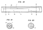
- FIG. 18 Another example of a fiberscope will be described with reference to Figs. 18 through 24.
- Figs. 18, 19 and 20 are diagrams showing the structure of the front end portion thereof, and
- Fig. 21 is a perspective view of the front end portion.
- An image pickup adapter 33 coupling an image forming lens to the front end of image fibers is fixedly bonded to the recess of a front end molded member 32 (manufactured according to a method described below) to hold illuminating light transmitting light guides.
- the outer wall of the front end molded part is fixedly bonded to the inner wall of a cover tube 1 2.8 mm in outside diameter and 2.2 mm in inside diameter and made of polyethylene resin or vinyl chloride resin.
- FIG. 19 and 20 are sectional views taken along lines A-A′ and B-B′, respectively, in Fig. 18.
- the adhesion of the outer wall of the front end molded part 82 to the cover tube 1 is reinforced by filling cover tube bonding holes 31 with an epoxy adhesive to overcome the shock which occurs when a flush of physiological saline is injected.
- a flush flow 34 is formed in this manner.
- the front end molded part is slightly retracted from the front end face of the cover tube.
- Figs. 22, 23 and 24 illustrate the aforementioned method of manufacturing the front end molded part.
- a metal mold made of a resin such as TeflonTM having a through-hole 2 mm in diameter and 10 mm in length is prepared.
- a bundle of plastic fibers used as the illuminating light transmitting light guides and a dummy tube 38 made of a resin such as TeflonTM for forming the recess 37 (Fig. 24) in the front end molded part 32 are inserted into the through-hole of the mold.
- the gap in the through-hole of the mold is filled with a resin such as an epoxy resin to form a preliminary part.
- the preliminary part After the resin has solidified, one end face of the preliminary part is polished, and the preliminary part is then removed from the metal mold 35. As a result, the preliminary part thus formed has one end face as shown in Fig. 23. Thereafter, the dummy tube 38 is removed, and then the preliminary part is partially cut so that the end face is as shown in Fig. 24.
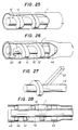
- FIG. 25 is a perspective view, with parts cut away, showing a fiberscope according to the invention.
- a spiral spacer 41 is laid around the end portion of a fiber bundle 12 including image transmitting image fibers having at the end thereof an optical system for forming the image of an object.
- the spacer 41 is arranged between the outer wall of the fiber bundle 12′ and the inner wall of a cover tube 1.
- the spiral spacer is a flexible belt-shaped member 42 made of vinyl chloride or the like which is bonded to the fiber bundle while being spirally wound thereon as shown in Fig. 26. Since the contact areas of the bonding surfaces of the spiral spacer can be made large, the spiral spacer can be readily and positively bonded to the fiber bundle.
- the spiral spacer 41 After being bonded to the fiber bundle 12′, the spiral spacer 41 is bonded to the inner wall of the cover tube 1. Thus, the cover tube 1 and the fiber bundle 12′ are secured to each other through the spacer.
- a fixing technique such as that illustrated in Figs. 26 and 28 may be employed.
- two ring namely a front ring 43 and a rear ring 44, are provided so that the spiral spacer 41 fixed to the fiber bundle 12′ cannot be moved back and forth in the axial direction due to the pulsating flow of transparent liquid in the liquid guide passageway 15′ in the cover tube 1.
- the rings 43 and 44 are made of a material which can be bonded positively to the cover tube 1, and therefore they can be fixedly bonded to the cover tube.
- a stop 45 is provided at a position on the outer wall of the fiber bundle 12′ 180° opposite the position of the end face of the spiral spacer engaged with the front ring 43. It is preferable that the stop 45 be in the form of a prism disposed with one edge against the flow of liquid.
- the end portion of the cover tube 1 is made larger in sectional area than the other portion so as to make the liquid guide passageway 15′ as large as possible. In this case, it may be unnecessary to fixedly bond the rear ring 44 to the cover tube 1.
- the spiral spacer 41 fixed to the end portion of the fiber bundle 12′ can be secured directly through the front and rear rings 43 and 44 to the cover tube 1 as described above.
- the bonding area is larger than that in conventional arrangement in which a small but intricately configured cap is bonded to the cover tube. Therefore, in accordance with the invention, the bonding operation can be achieved readily and positively. Thus, the drawback of the conventional fiberscope of the possibility of the cap being dislodged by the shock caused when the liquid is injected is eliminated.
- a spiral spacer made of belt-shaped flexible material is secured to the outer wall of the front end portion of the fiber bundle, including the image transmitting image fibers along with their associated optical system and illuminating light transmitting light guides arranged along the image fibers.
- the spiral spacer extends in the axial direction of the fiber bundle in the liquid passageway formed between the outerwall of the fiber bundle and the inner wall of the cover tube which covers the fiber bundle.
- the liquid passageway is spiral, the liquid is injected with a spiral flow, which contributes to the quick displacement of the opaque liquid in the region under observation.
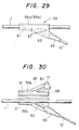
- a substantially Y-shaped rigid branching mount 59 is used to cover the seal the branching section of the flexible tube 1 and the fiber bundle 12′.
- the branching mount 59 as shown in these figures, is made up of two parts, namely, upper and lower halves 59b and 59a of a substantially symmetrical configuration.
- the branching mount 59 has a tube guide passageway 61 which maintains the flexible tube 1 straight and a fiber guide passageway 63 for accommodating the fiber bundle 12′.
- the fiber guide passageway 63 branches from the tube guide passageway 61.
- the halves 59a and 59b of the branching mount 59 can be formed by aluminum casting or resin molding.
- Each of the guide passages 61 and 63 has a number of grooves 65 which extend substantially perpendicularly to the axial direction. Therefore, when the halves 59a and 59b are joined together, they engage the outer walls of the flexible tube 1 and the fiber bundle 12′ to positively hold them.
- a water-resistant adhesive is applied to the guide passageways 61 and 63 and the outer walls of the flexible tube 1 and the fiber bundle 12′ which are laid along the guide passageways.
- a rubber bushing 69 having a passage for receiving the fiber body is provided at the outlet of the fiber guide passageway 63 of the mount 59.
- a holding structure 71 (which takes the form of an annular groove in the figures) for holding an end portion of the bushing 69 is formed at the outlet of the passageway 63.
- Such a rubber bushing may be provided at the outlet of the passageway for the flexible tube 1 in the branching mount 59.
- the branching section thus constructed is rigid because it is covered in its entirety by the rigid branching mount.
- the seal is positive because the tube 1 and the fiber bundle 12′ cannot move appreciably in the branching mount 59 when the branching section is covered by the branching mount.
- the branching mount 59 can be manufactured at a low cost by a casting or resin molding process.
- the formation of the branching section is considerably simple because it can be achieved merely by joining the halves of the branching mount to which adhesive has been applied.
- the optical fiber can be sufficiently reinforced by providing the rubber bushing 59 at the outlet of the branching mount.
- Embodiments of the invention have been described with reference to a medical fiberscope for observing or measuring the inside of a blood vessel or the heart.
- the invention is not limited thereto or thereby. That is, for instance, the fiberscope according to the invention may be used to observe or measure the inside of a pipe or tank containing an opaque liquid such as crude oil.
Landscapes
- Health & Medical Sciences (AREA)
- Life Sciences & Earth Sciences (AREA)
- Surgery (AREA)
- Optics & Photonics (AREA)
- Physics & Mathematics (AREA)
- Biophysics (AREA)
- Medical Informatics (AREA)
- Radiology & Medical Imaging (AREA)
- Nuclear Medicine, Radiotherapy & Molecular Imaging (AREA)
- Engineering & Computer Science (AREA)
- Biomedical Technology (AREA)
- Heart & Thoracic Surgery (AREA)
- Pathology (AREA)
- Molecular Biology (AREA)
- Animal Behavior & Ethology (AREA)
- General Health & Medical Sciences (AREA)
- Public Health (AREA)
- Veterinary Medicine (AREA)
- Endoscopes (AREA)
Claims (15)
Applications Claiming Priority (8)
| Application Number | Priority Date | Filing Date | Title |
|---|---|---|---|
| JP58048205A JPS59172621A (ja) | 1983-03-22 | 1983-03-22 | フアイバスコ−プ |
| JP48205/83 | 1983-03-22 | ||
| JP54347/83U | 1983-04-12 | ||
| JP1983054347U JPS59161119U (ja) | 1983-04-12 | 1983-04-12 | フアイバスコ−プ |
| JP68861/83 | 1983-04-19 | ||
| JP58068861A JPS59195216A (ja) | 1983-04-19 | 1983-04-19 | フアイバスコ−プ |
| JP186268/83U | 1983-11-30 | ||
| JP1983186268U JPS6092224U (ja) | 1983-11-30 | 1983-11-30 | フアイバスコ−プ |
Publications (3)
| Publication Number | Publication Date |
|---|---|
| EP0119614A1 EP0119614A1 (fr) | 1984-09-26 |
| EP0119614B1 EP0119614B1 (fr) | 1987-08-05 |
| EP0119614B2 true EP0119614B2 (fr) | 1992-04-08 |
Family
ID=27462161
Family Applications (1)
| Application Number | Title | Priority Date | Filing Date |
|---|---|---|---|
| EP19840102942 Expired EP0119614B2 (fr) | 1983-03-22 | 1984-03-16 | Fibroscope |
Country Status (3)
| Country | Link |
|---|---|
| EP (1) | EP0119614B2 (fr) |
| CA (1) | CA1212287A (fr) |
| DE (1) | DE3465164D1 (fr) |
Families Citing this family (5)
| Publication number | Priority date | Publication date | Assignee | Title |
|---|---|---|---|---|
| EP0188273B1 (fr) | 1985-01-14 | 1991-08-28 | Sumitomo Electric Industries Limited | Endoscope à fibres optiques |
| US4869246A (en) * | 1987-12-11 | 1989-09-26 | Adair Edwin Lloyd | Method for controllably embolyzing blood vessels |
| US4920413A (en) * | 1989-02-28 | 1990-04-24 | Olympus Optical Co., Ltd. | Blood-vessel endoscope system for storing a frozen picture in synchronization with heart pulsation |
| US5263928A (en) * | 1991-06-14 | 1993-11-23 | Baxter International Inc. | Catheter and endoscope assembly and method of use |
| JP4128496B2 (ja) | 2003-07-30 | 2008-07-30 | オリンパス株式会社 | 超音波処置装置 |
Family Cites Families (4)
| Publication number | Priority date | Publication date | Assignee | Title |
|---|---|---|---|---|
| US3866599A (en) * | 1972-01-21 | 1975-02-18 | Univ Washington | Fiberoptic catheter |
| US4423727A (en) * | 1981-04-10 | 1984-01-03 | Jerrold Widran | Continuous flow urological endoscopic apparatus and method of using same |
| US4759348A (en) * | 1981-09-28 | 1988-07-26 | Cawood Charles David | Endoscope assembly and surgical instrument for use therewith |
| JPS592005A (ja) * | 1982-06-26 | 1984-01-07 | Sumitomo Electric Ind Ltd | センサ用光フアイバ |
-
1984
- 1984-03-16 DE DE8484102942T patent/DE3465164D1/de not_active Expired
- 1984-03-16 EP EP19840102942 patent/EP0119614B2/fr not_active Expired
- 1984-03-21 CA CA000450077A patent/CA1212287A/fr not_active Expired
Also Published As
| Publication number | Publication date |
|---|---|
| CA1212287A (fr) | 1986-10-07 |
| EP0119614B1 (fr) | 1987-08-05 |
| DE3465164D1 (en) | 1987-09-10 |
| EP0119614A1 (fr) | 1984-09-26 |
Similar Documents
| Publication | Publication Date | Title |
|---|---|---|
| US4569335A (en) | Fiberscope | |
| US4576146A (en) | Fiberscope | |
| EP0097934B1 (fr) | Cathéter transmetteur d'images à fibres optiques composées et procédé de fabrication | |
| US4576145A (en) | Fiberscope | |
| US4784144A (en) | Optical fiber image sensor | |
| US4717387A (en) | Catheter | |
| US4807597A (en) | Fiberscope | |
| EP3919109B1 (fr) | Cathéter à ballonnet intra-aortique | |
| EP0119614B2 (fr) | Fibroscope | |
| JPS59111125A (ja) | フアイバスコ−プ | |
| JPH034830A (ja) | 内視鏡 | |
| KR870001167Y1 (ko) | 파이버 스코우프 | |
| NO168078B (no) | Skjoeteanordning for flerpunkts sammenkobling av optiske fiberkabler. | |
| KR870000308B1 (ko) | 파이버 스코오프 | |
| JP3517290B2 (ja) | 内視鏡の先端部 | |
| JP3462602B2 (ja) | 内視鏡の先端部 | |
| JPS59155824A (ja) | 光フアイバセンサ分岐部構造 | |
| US20050288554A1 (en) | Endoscope | |
| KR870000569Y1 (ko) | 파이버 스코오프 | |
| JPH055530Y2 (fr) | ||
| JPS5928122A (ja) | 画像観察部 | |
| JP2799185B2 (ja) | 内視鏡 | |
| JP2512483B2 (ja) | カテ−テルチュ−ブおよびその製造方法 | |
| JP2756168B2 (ja) | 管路内へのパイプ引き込み方法 | |
| JPS59154420A (ja) | 光フアイバセンサ分岐部の構造 |
Legal Events
| Date | Code | Title | Description |
|---|---|---|---|
| PUAI | Public reference made under article 153(3) epc to a published international application that has entered the european phase |
Free format text: ORIGINAL CODE: 0009012 |
|
| AK | Designated contracting states |
Designated state(s): DE FR GB IT NL SE |
|
| 17P | Request for examination filed |
Effective date: 19841221 |
|
| 17Q | First examination report despatched |
Effective date: 19860122 |
|
| D17Q | First examination report despatched (deleted) | ||
| GRAA | (expected) grant |
Free format text: ORIGINAL CODE: 0009210 |
|
| ITF | It: translation for a ep patent filed | ||
| AK | Designated contracting states |
Kind code of ref document: B1 Designated state(s): DE FR GB IT NL SE |
|
| REF | Corresponds to: |
Ref document number: 3465164 Country of ref document: DE Date of ref document: 19870910 |
|
| ET | Fr: translation filed | ||
| PLBI | Opposition filed |
Free format text: ORIGINAL CODE: 0009260 |
|
| 26 | Opposition filed |
Opponent name: OLYMPUS OPTICAL COMPANY LIMITED Effective date: 19880423 |
|
| NLR1 | Nl: opposition has been filed with the epo |
Opponent name: OLYMPUS OPTICAL COMPANY LIMITED |
|
| ITTA | It: last paid annual fee | ||
| ITF | It: translation for a ep patent filed | ||
| PUAH | Patent maintained in amended form |
Free format text: ORIGINAL CODE: 0009272 |
|
| STAA | Information on the status of an ep patent application or granted ep patent |
Free format text: STATUS: PATENT MAINTAINED AS AMENDED |
|
| 27A | Patent maintained in amended form |
Effective date: 19920408 |
|
| AK | Designated contracting states |
Kind code of ref document: B2 Designated state(s): DE FR GB IT NL SE |
|
| NLR2 | Nl: decision of opposition | ||
| ET3 | Fr: translation filed ** decision concerning opposition | ||
| NLR3 | Nl: receipt of modified translations in the netherlands language after an opposition procedure | ||
| EAL | Se: european patent in force in sweden |
Ref document number: 84102942.4 |
|
| PGFP | Annual fee paid to national office [announced via postgrant information from national office to epo] |
Ref country code: DE Payment date: 19950309 Year of fee payment: 12 |
|
| PGFP | Annual fee paid to national office [announced via postgrant information from national office to epo] |
Ref country code: SE Payment date: 19950315 Year of fee payment: 12 |
|
| PGFP | Annual fee paid to national office [announced via postgrant information from national office to epo] |
Ref country code: NL Payment date: 19950331 Year of fee payment: 12 |
|
| PGFP | Annual fee paid to national office [announced via postgrant information from national office to epo] |
Ref country code: GB Payment date: 19960307 Year of fee payment: 13 |
|
| PGFP | Annual fee paid to national office [announced via postgrant information from national office to epo] |
Ref country code: FR Payment date: 19960315 Year of fee payment: 13 |
|
| PG25 | Lapsed in a contracting state [announced via postgrant information from national office to epo] |
Ref country code: SE Effective date: 19960317 |
|
| PG25 | Lapsed in a contracting state [announced via postgrant information from national office to epo] |
Ref country code: NL Effective date: 19961001 |
|
| NLV4 | Nl: lapsed or anulled due to non-payment of the annual fee |
Effective date: 19961001 |
|
| PG25 | Lapsed in a contracting state [announced via postgrant information from national office to epo] |
Ref country code: DE Effective date: 19961203 |
|
| EUG | Se: european patent has lapsed |
Ref document number: 84102942.4 |
|
| PG25 | Lapsed in a contracting state [announced via postgrant information from national office to epo] |
Ref country code: GB Effective date: 19970316 |
|
| GBPC | Gb: european patent ceased through non-payment of renewal fee |
Effective date: 19970316 |
|
| PG25 | Lapsed in a contracting state [announced via postgrant information from national office to epo] |
Ref country code: FR Free format text: LAPSE BECAUSE OF NON-PAYMENT OF DUE FEES Effective date: 19971128 |
|
| REG | Reference to a national code |
Ref country code: FR Ref legal event code: ST |