EP0119777A2 - Pompe à chaleur centrifuge - Google Patents
Pompe à chaleur centrifuge Download PDFInfo
- Publication number
- EP0119777A2 EP0119777A2 EP84301402A EP84301402A EP0119777A2 EP 0119777 A2 EP0119777 A2 EP 0119777A2 EP 84301402 A EP84301402 A EP 84301402A EP 84301402 A EP84301402 A EP 84301402A EP 0119777 A2 EP0119777 A2 EP 0119777A2
- Authority
- EP
- European Patent Office
- Prior art keywords
- heat pump
- plates
- condenser
- evaporator
- face
- Prior art date
- Legal status (The legal status is an assumption and is not a legal conclusion. Google has not performed a legal analysis and makes no representation as to the accuracy of the status listed.)
- Granted
Links
Images




Classifications
-
- F—MECHANICAL ENGINEERING; LIGHTING; HEATING; WEAPONS; BLASTING
- F25—REFRIGERATION OR COOLING; COMBINED HEATING AND REFRIGERATION SYSTEMS; HEAT PUMP SYSTEMS; MANUFACTURE OR STORAGE OF ICE; LIQUEFACTION SOLIDIFICATION OF GASES
- F25B—REFRIGERATION MACHINES, PLANTS OR SYSTEMS; COMBINED HEATING AND REFRIGERATION SYSTEMS; HEAT PUMP SYSTEMS
- F25B3/00—Self-contained rotary compression machines, i.e. with compressor, condenser and evaporator rotating as a single unit
Definitions
- This invention is concerned with heat pumps, of the compression type, and is a new form of heat pump which is of a rotary design.
- Compression heat pumps have been developed within the last few decades to the point where pumps are now available suitable for industrial purposes or for the domestic heating market. Compared with more conventional forms of heating, in particular water boilers fired by oil, gas or solid fuel, they are expensive and cumbersome. However they are also more economical in operation than many other prior heating systems and there is therefore a continuing search for an improved, more compact design.
- the main object of the present invention is to provide a new form of heat pump which is capable of being designed in very compact form.
- a compression heat pump which comprises at least an evaporator, a compressor and a condenser, characterised in that at least one of the aforesaid components (excluding the compressor) is in the form of one or more rotatable plates, preferably a plurality of axially-spaced, parallel rotatable plates, across the thickness of which plates, a heat transfer takes place.
- each of the above mentioned components of the heat pump that is evaporator, and condenser, is in the form of one or more rotatable plates across the thickness of which a heat transfer takes place.
- a rotary compression heat pump according to the present invention comprises:
- the plates used in the compression heat pump according to the present invention are typically in the form of discs or annuli.
- the face of the plates in the condenser over which working fluid vapour flows and on which it condenses has a surface designed to discourage the formation of a continuous liquid film thereon.
- the face of the plates is treated such that (a) condensation of the working fluid vapour thereon occurs in a dropwise fashion and (b) its wettability is reduced such that formation of any continuous, stable liquid film is discouraged.
- Such treatments include provision of a coating of interalia a suitable silicone or polytetrafluoroethylene on the surface of the plates.
- the face of the plates in the evaporator over which flows the liquid working fluid and from which it is to be evaporated may advantageously be treated so as to assist the retention of a continuous film of liquid thereon.
- Such treatment which may be chemical, e.g. etching, or physical, e.g. sand-blasting, will in general be aimed at giving the surface an overall fine roughness.
- the thickness of the plates employed in the compression heat pump according to the present invention is generally between 0.1 mm and 5 mms, depending upon the material of construction, the specific evaporation or condensation to be carried out thereon and the form of surface features-chosen. While the thickness of the plate may vary - and obviously will vary with some forms of surface features - in-general when referring to plate thickness we refer to the plate thickness as it would be without those features. It will be appreciated that the thickness of the plates-should be sufficient to provide the necessary rigidity under operating conditions but thin enough to permit high thermal flux from one face to another. Typically the plate thickness is between 0.25 mm and 1.25 mm.
- the outer diameter of the plates used in the rotary compression heat pump of the present invention is typically in the range 10 cm to 5 metres and is preferably between about 50 cm and 100 cm and where the plates are in the form of annuli the inner diameter thereof is typically in the range 5 cm to 1 metre.
- a component of a heat pump according to the present invention comprises a plurality of plates they are mounted substantially parallel to each other along the common axis about which they are able to rotate and are closely adjacent to one another to form narrow passages.
- the mean axial depth of the passages between adjacent plates is between 0.5 mm and 10 mm and more preferably is between 2 mm and 3 mm.
- the plates used in rotary compression heat pumps according to the present invention are made of a suitable thermally conductive material which is able to withstand any environment to which it may be subjected during operation of the heat pump.
- suitable materials may be mentioned inter alia mild steel, stainless steel, copper and aluminuim.
- the plates, in operation, are rotated at speed as to subject any liquid thereon to a mean acceleration, measured in a radial direction with respect to the axis of rotation, greater than the acceleration due to gravity, 'g'.
- the particular value selected depends upon such considerations as the size of the plates, the heat flow therethrough and the desired capacity of the heat pump in terms both of heat output and of quanitity of liquid to be treated on the plates.
- the acceleration may lie within the range from 5 to 1000g, especially from 50 to 750 g and more preferably from 100 to 600 g.
- a liquid to be evaporated from a plate in the evaporator of the heat pump according to the present invention is conveniently fed to the plate adjacent its axis of rotation, for example to the centre of the plate.
- Liquid formed by condensation on a face of a plate in the condenser of the heat pump of the present invention flows radially outwards and is discharged adjacent the periphery thereof. Vapour generated from a face of a plate in the evaporator may be discharged adjacent the axis or the periphery of the plate.
- the drive means used in the rotary heat pump according to the present invention is a belt driven by an electric motor.
- other drive means e.g. direct drive from an electric motor, known in the rotary devices art may be used.
- the compressor used in the rotary compression heat pump according to the present invention may be any suitable compresor which may be used for compressing a vapour and has a suitable capacity, conveniently it is of a gear pump type.
- the working fluids which are suitable for use with the heat pump according to the present invention may be those which are already known in the compression heat pump field.
- Preferred working fluids are the chlorofluorohydrocarbons well known as refrigerants, for example Refrigerant 124, which is monochlorotetra- fluoroethane, trichlorofluoromethane and 1,2,2-trichloro-1,1,_2-trifluoroethane.
- the ambient fluid source of heat which is fed to the evaporator may be water, for example from a river or pond, or preferably air.
- the medium which is to be heated by absorbing heat in the condenser of the rotary compression heat pump according to the present invention may be a liquid, e.g. water, or preferably an innocuous gas, more preferably air.
- the design of the heat pump according to the present invention may be such that its mode of operation may be reversed so that it may act, at different times, as both a heat pump and an air-conditioning cooling unit in a domestic environment.
- a working fluid such as a chlorofluorohydrocarbon refrigerant is circulated by means of a compressor P around a system consisting of a condenser C, a suitable valve V and evaporator E, in that sequence.
- the working fluid is vaporised by heat exchange with a flow of an ambient source of heat flowing through line 6.
- the vapour passes via line 1 to the compressor P where its pressure is increased. Vapour from the compressor P is charged to the condenser C, in which it loses heat to a medium to be heated flowing in line 3 and is condensed to liquid.
- the liquid is finally returned to the evaporator E via line 4, an expansion valve V, and line 5.
- the heat input to the heat pump is the low grade heat taken from the ambient fluid at the evaporator E.
- the heat output is that taken up by the medium to be heated in the condenser C.
- the embodiment of the heat pump according to the present invention illustrated schematically in Figure 2 comprises the components of Figure 1 mounted in the illustrated sequence upon a shaft at S, for rotation therewith.
- parts corresponding to those of Figure 1 are indicated by the use of the same numbering and lettering.
- the sequence of flow of fluids through the heat pump is essentially the same as in Figure 1, although the placing of the components in close juxtaposition upon a rotating shaft makes possible the assembly of a more compact unit than would be apparent from Figure 1.
- the line 6 in Figure 2 is the route by which ambient air is introduced to the evaporator.
- the line 3 in Figure 2 is the route by which a liquid medium to be heated passes through the rotary compression heat pump.
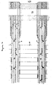
- a heat pump according to the present invention-in which the medium to be heated is gaseous is illustrated in radial section in Figure 3, wherein the axis of rotation is again identified by the letter S.
- those portions of the heat pump rotor which perform functions already mentioed in connection with Figures 1 and 2, namely the condenser, compressor and evaporator, are indicated by the letters C, P, and E respectively.
- the illustrated heat pump is symmetrical about the axis S and is largely formed of a series of assorted discs and annular plates, of varying profiles.
- the discs and annular plates may be formed by stamping sheet metal and the heat pump may be assembled by stacking the discs and annular plates in appropriate sequence about a tubular conduit 7 which forms the axial support for the structure.
- Plates 12 and 13 define radial channels through which liquid working fluid is fed to manifold 14 and thence via ports 15 to the radial passages 16 defined by pairs of plates 11.
- the passages are provided with separator plates 17 which give support to the overall structure of the evaporator. Liquid working fluid, by absorbing heat from the air in passages 9, across the thickness of plates 11, is converted to vapour which flows radially outwards into channel 18, adjacent to the outer circumferences of the rotor and thence to the compressor P.
- vaporised working fluid is conveyed, under pressure, via channel 19 to the condenser C.
- condenser C which is of similar structure to evaporator E
- the compressed vapour flows radially outwards through radial passages 22 defined by pairs of plates 20 and provided with supporting plates.
- the passages 21 for a gaseous medium to be heated, e.g. air, between the pairs of plates are fitted with fins.
- Vapour in the passages 22 condenses to form liquid working fluid on the faces of the plates 20 by loss of heat across the thickness of plates 20 to the gaseous medium to be heated, typically air, which enters theheat pump via aperture 25 and flows radially outwards through the passages 21.
- the liquid working fluid is collected in channel 23 adjacent the priphery of the rotor and is returned via a throttle valve (not shown) and an axially disposed channel 24 to the radial channel defined by plates 12 and 13.
- a heat pump according to the present invention in which the medium to be heated is liquid is illustrated in radial section in Figure 5, wherein the axis of rotation is again identified by the letter S.
- Figures 5 and 6 parts corresponding to those of figures 3 and 4 are indicated by use of the same numbering and lettering.
- the evaporator E and compressor P in Figure 5 have the same structure and mode of operation as the evaporator and compressor in Figure 3.
- vaporised working fluid is conveyed, under pressure, via channel 19 to the condenser C.
- the vapour is conveyed via a plurality of apertures 34, symmetrically disposed around the axis, to an assembly of plates 26, 27, 28, 29, 30, 31, 32 and 33 which are arranged to form alternate channels for flow of working fluid (illustrated in Figure 6(a)) and liquid medium to be heated (illustrated in Figure 6(b).
- the vapour flows between the plates and condenses on the faces thereof.
- Liquid working fluid flows radially outwards and is collected in channel 23 adjacent the periphery of the rotor and is returned via a throttle valve (not shown) and axially disposed channel 24 to the radial channel defined by plates 12 and 13.
- Liquid medium to be heated typically water
- conduit 7 Liquid medium to be heated
- a plurality of apertures 36 disposed symmetrically around the conduit and adjacent thereto, to the assembly of plates.
- the water flows radially outwards and then radiallly inwards and gains heat across the thickness of the plates from condensation of the working fluid.
- the liquid medium to be heated is discharged via port 38 into line 37 in conduit 7.
- the present invention is further illustrated by the following example.
- the working fluid is a halogenated hydrocarbon refrigerant.
Landscapes
- Engineering & Computer Science (AREA)
- Physics & Mathematics (AREA)
- Mechanical Engineering (AREA)
- Thermal Sciences (AREA)
- General Engineering & Computer Science (AREA)
- Structures Of Non-Positive Displacement Pumps (AREA)
- Compression-Type Refrigeration Machines With Reversible Cycles (AREA)
- Heat-Exchange Devices With Radiators And Conduit Assemblies (AREA)
- Central Heating Systems (AREA)
- Sorption Type Refrigeration Machines (AREA)
- Lubrication Of Internal Combustion Engines (AREA)
- Vaporization, Distillation, Condensation, Sublimation, And Cold Traps (AREA)
Priority Applications (1)
| Application Number | Priority Date | Filing Date | Title |
|---|---|---|---|
| AT84301402T ATE38891T1 (de) | 1983-03-24 | 1984-03-02 | Zentrifugalwaermepumpe. |
Applications Claiming Priority (2)
| Application Number | Priority Date | Filing Date | Title |
|---|---|---|---|
| GB8308137 | 1983-03-22 | ||
| GB838308137A GB8308137D0 (en) | 1983-03-24 | 1983-03-24 | Compression-type heat pumps |
Publications (3)
| Publication Number | Publication Date |
|---|---|
| EP0119777A2 true EP0119777A2 (fr) | 1984-09-26 |
| EP0119777A3 EP0119777A3 (en) | 1985-08-07 |
| EP0119777B1 EP0119777B1 (fr) | 1988-11-23 |
Family
ID=10540143
Family Applications (1)
| Application Number | Title | Priority Date | Filing Date |
|---|---|---|---|
| EP84301402A Expired EP0119777B1 (fr) | 1983-03-22 | 1984-03-02 | Pompe à chaleur centrifuge |
Country Status (11)
| Country | Link |
|---|---|
| US (1) | US4793154A (fr) |
| EP (1) | EP0119777B1 (fr) |
| JP (1) | JPS59183271A (fr) |
| AT (1) | ATE38891T1 (fr) |
| AU (1) | AU565523B2 (fr) |
| CA (1) | CA1261159A (fr) |
| DE (1) | DE3475339D1 (fr) |
| DK (1) | DK163942C (fr) |
| GB (1) | GB8308137D0 (fr) |
| NO (1) | NO161087C (fr) |
| NZ (1) | NZ207472A (fr) |
Cited By (4)
| Publication number | Priority date | Publication date | Assignee | Title |
|---|---|---|---|---|
| AU571298B2 (en) * | 1984-01-06 | 1988-04-14 | Imperial Chemical Industries Plc | Heat pumps |
| WO1997003326A1 (fr) * | 1995-07-13 | 1997-01-30 | Haga Engineering A.S | Pompe a chaleur rotative |
| WO2015161330A1 (fr) * | 2014-04-23 | 2015-10-29 | Ecop Technologies Gmbh | Dispositif et procédé de conversion d'énergie thermique |
| WO2015165432A3 (fr) * | 2014-04-11 | 2015-12-23 | Rolf Kranen | Dispositif pour générer une différence de température |
Families Citing this family (4)
| Publication number | Priority date | Publication date | Assignee | Title |
|---|---|---|---|---|
| GB8308135D0 (en) * | 1983-03-24 | 1983-05-05 | Ici Plc | Centrifugal heat pump |
| GB8802152D0 (en) * | 1988-02-02 | 1988-03-02 | Ici Plc | Heat pumps |
| US5303565A (en) * | 1993-03-11 | 1994-04-19 | Conserve Resources, Inc. | Rotary absorption heat pump of improved performance |
| AT509231B1 (de) | 2010-05-07 | 2011-07-15 | Bernhard Adler | Vorrichtung und verfahren zum umwandeln thermischer energie |
Family Cites Families (20)
| Publication number | Priority date | Publication date | Assignee | Title |
|---|---|---|---|---|
| CH141975A (de) * | 1928-05-24 | 1930-08-31 | Brown Boveri & Cie Aktiegesell | Umlaufende Wärmeaustauschvorrichtung für Kältemaschinen. |
| US2498661A (en) * | 1945-10-29 | 1950-02-28 | Gen Motors Corp | Refrigerating apparatus for window mounting |
| DE833049C (de) * | 1949-06-29 | 1952-03-03 | Bbc Brown Boveri & Cie | Einrichtung zur Erzielung einer Tropfenkondensation bei Kondensationsanlagen |
| US2609672A (en) * | 1951-05-04 | 1952-09-09 | Ind Patent Corp | Unitized centrifugal refrigerating machine |
| US2788644A (en) * | 1952-10-08 | 1957-04-16 | Kooperativa Foerbundet | Refrigerating chamber and freezing box arrangements |
| US2979921A (en) * | 1958-08-04 | 1961-04-18 | Thompson Ramo Wooldridge Inc | Vapor compression apparatus |
| US3877515A (en) * | 1969-06-17 | 1975-04-15 | Nikolaus Laing | Temperature-control system with rotary heat exchangers |
| CH446410A (de) * | 1964-01-22 | 1967-11-15 | Braun Ag | Wärmepumpe |
| GB1042386A (en) * | 1964-03-19 | 1966-09-14 | Serck Tubes Ltd | Surface condensers for steam and other vapours |
| US3456454A (en) * | 1967-01-10 | 1969-07-22 | Frederick W Kantor | Centrifugal absorptive thermodynamic apparatus and method |
| US3740966A (en) * | 1971-12-17 | 1973-06-26 | Dynatherm Corp | Rotary heat pump |
| GB1466580A (en) * | 1973-05-17 | 1977-03-09 | Eskeli M | Heat exchange apparatus |
| US4144721A (en) * | 1974-04-16 | 1979-03-20 | Kantor Frederick W | Rotary thermodynamic apparatus |
| US3999402A (en) * | 1974-04-22 | 1976-12-28 | Nelson Daniel E | Cam drive pump refrigerators |
| US4022032A (en) * | 1975-12-16 | 1977-05-10 | Nott Clinton W | Refrigeration system |
| FR2385366A1 (fr) * | 1977-04-01 | 1978-10-27 | Fleuret Michel | Vitrine de congelation |
| DE3010450A1 (de) * | 1980-03-19 | 1981-09-24 | Kabel- und Metallwerke Gutehoffnungshütte AG, 3000 Hannover | Rohr fuer waermetauscherzwecke, insbesondere fuer verdampfer |
| DE3173876D1 (en) * | 1980-08-11 | 1986-04-03 | Centre Nat Rech Scient | Device and systems for the revaluation of low-level thermal energy using phenomena of evaporation, and solution of two fluids being in equilibrium of vapour pressure at different temperatures |
| FR2500143A1 (fr) * | 1981-02-13 | 1982-08-20 | Aragou Yvan | Echangeurs de chaleur a structure capillaire, pour machines frigorifiques et/ou pompes a chaleur |
| EP0080328B1 (fr) * | 1981-11-24 | 1985-11-06 | Imperial Chemical Industries Plc | Appareil centrifuge |
-
1983
- 1983-03-24 GB GB838308137A patent/GB8308137D0/en active Pending
-
1984
- 1984-03-02 DE DE8484301402T patent/DE3475339D1/de not_active Expired
- 1984-03-02 EP EP84301402A patent/EP0119777B1/fr not_active Expired
- 1984-03-02 AT AT84301402T patent/ATE38891T1/de not_active IP Right Cessation
- 1984-03-12 NZ NZ207472A patent/NZ207472A/en unknown
- 1984-03-16 AU AU25813/84A patent/AU565523B2/en not_active Ceased
- 1984-03-19 DK DK158684A patent/DK163942C/da not_active IP Right Cessation
- 1984-03-20 NO NO841075A patent/NO161087C/no unknown
- 1984-03-22 JP JP59053652A patent/JPS59183271A/ja active Granted
- 1984-03-22 CA CA000450282A patent/CA1261159A/fr not_active Expired
-
1985
- 1985-07-01 US US06/750,276 patent/US4793154A/en not_active Expired - Fee Related
Cited By (6)
| Publication number | Priority date | Publication date | Assignee | Title |
|---|---|---|---|---|
| AU571298B2 (en) * | 1984-01-06 | 1988-04-14 | Imperial Chemical Industries Plc | Heat pumps |
| WO1997003326A1 (fr) * | 1995-07-13 | 1997-01-30 | Haga Engineering A.S | Pompe a chaleur rotative |
| US5901568A (en) * | 1995-07-13 | 1999-05-11 | Haga Engineering As | Rotating heat pump |
| WO2015165432A3 (fr) * | 2014-04-11 | 2015-12-23 | Rolf Kranen | Dispositif pour générer une différence de température |
| WO2015161330A1 (fr) * | 2014-04-23 | 2015-10-29 | Ecop Technologies Gmbh | Dispositif et procédé de conversion d'énergie thermique |
| US10247450B2 (en) | 2014-04-23 | 2019-04-02 | Ecop Technologies Gmbh | Device and method for converting thermal energy |
Also Published As
| Publication number | Publication date |
|---|---|
| AU565523B2 (en) | 1987-09-17 |
| DE3475339D1 (en) | 1988-12-29 |
| NZ207472A (en) | 1986-10-08 |
| EP0119777B1 (fr) | 1988-11-23 |
| AU2581384A (en) | 1984-09-27 |
| DK163942B (da) | 1992-04-21 |
| JPS59183271A (ja) | 1984-10-18 |
| US4793154A (en) | 1988-12-27 |
| NO841075L (no) | 1984-09-24 |
| DK163942C (da) | 1992-09-21 |
| NO161087B (no) | 1989-03-20 |
| GB8308137D0 (en) | 1983-05-05 |
| EP0119777A3 (en) | 1985-08-07 |
| DK158684D0 (da) | 1984-03-19 |
| JPH0549907B2 (fr) | 1993-07-27 |
| CA1261159A (fr) | 1989-09-26 |
| NO161087C (no) | 1989-06-28 |
| ATE38891T1 (de) | 1988-12-15 |
| DK158684A (da) | 1984-09-23 |
Similar Documents
| Publication | Publication Date | Title |
|---|---|---|
| EP0052452A2 (fr) | Machine thermique à effet variable | |
| GB2049901A (en) | Heat Pump Apparatus and Method of Recovering Heat Utilizing the Same | |
| WO1993007425A1 (fr) | Systeme et dispositif a thermopompe a cycle stirling inverse a ecoulement constant | |
| EP0119777B1 (fr) | Pompe à chaleur centrifuge | |
| US3986852A (en) | Rotary cooling and heating apparatus | |
| US3791167A (en) | Heating and cooling wheel with dual rotor | |
| US3828573A (en) | Heating and cooling wheel | |
| GB2104637A (en) | Pitot heat pump | |
| US3397739A (en) | Heat exchange apparatus | |
| EP0119776B1 (fr) | Pompe à chaleur centrifuge | |
| US3948061A (en) | Centrifugal refrigeration unit | |
| US4010018A (en) | Rotary thermodynamic apparatus and method | |
| US4656839A (en) | Heat pumps | |
| US4512394A (en) | Variable effect absorption machine and process | |
| US4107944A (en) | Heat pump with two rotors | |
| US4494386A (en) | Vapor refrigeration cycle system with constrained rotary vane compressor and low vapor pressure refrigerant | |
| US3559419A (en) | Centrifugal absorbtive thermodynamic apparatus and method | |
| US3621665A (en) | Thermal pump and process | |
| US6003324A (en) | Multi-rotor helical screw compressor with unloading | |
| US5572882A (en) | Low pressure air cycle cooling device | |
| US4441337A (en) | Rotary thermodynamic apparatus and method | |
| US4211093A (en) | Vapor cycle cooling system | |
| US4438636A (en) | Heat-actuated air conditioner/heat pump | |
| US4429662A (en) | Method and apparatus for generating vapor | |
| US5297619A (en) | Centrifugal heat pipe vapor absorption heat pump |
Legal Events
| Date | Code | Title | Description |
|---|---|---|---|
| PUAI | Public reference made under article 153(3) epc to a published international application that has entered the european phase |
Free format text: ORIGINAL CODE: 0009012 |
|
| AK | Designated contracting states |
Designated state(s): AT BE CH DE FR GB IT LI NL SE |
|
| PUAL | Search report despatched |
Free format text: ORIGINAL CODE: 0009013 |
|
| AK | Designated contracting states |
Designated state(s): AT BE CH DE FR GB IT LI NL SE |
|
| 17P | Request for examination filed |
Effective date: 19851217 |
|
| 17Q | First examination report despatched |
Effective date: 19860602 |
|
| GRAA | (expected) grant |
Free format text: ORIGINAL CODE: 0009210 |
|
| AK | Designated contracting states |
Kind code of ref document: B1 Designated state(s): AT BE CH DE FR GB IT LI NL SE |
|
| REF | Corresponds to: |
Ref document number: 38891 Country of ref document: AT Date of ref document: 19881215 Kind code of ref document: T |
|
| ITF | It: translation for a ep patent filed | ||
| REF | Corresponds to: |
Ref document number: 3475339 Country of ref document: DE Date of ref document: 19881229 |
|
| ET | Fr: translation filed | ||
| PLBE | No opposition filed within time limit |
Free format text: ORIGINAL CODE: 0009261 |
|
| STAA | Information on the status of an ep patent application or granted ep patent |
Free format text: STATUS: NO OPPOSITION FILED WITHIN TIME LIMIT |
|
| 26N | No opposition filed | ||
| ITTA | It: last paid annual fee | ||
| PGFP | Annual fee paid to national office [announced via postgrant information from national office to epo] |
Ref country code: FR Payment date: 19940209 Year of fee payment: 11 |
|
| PGFP | Annual fee paid to national office [announced via postgrant information from national office to epo] |
Ref country code: CH Payment date: 19940211 Year of fee payment: 11 |
|
| PGFP | Annual fee paid to national office [announced via postgrant information from national office to epo] |
Ref country code: AT Payment date: 19940214 Year of fee payment: 11 |
|
| PGFP | Annual fee paid to national office [announced via postgrant information from national office to epo] |
Ref country code: SE Payment date: 19940216 Year of fee payment: 11 |
|
| PGFP | Annual fee paid to national office [announced via postgrant information from national office to epo] |
Ref country code: DE Payment date: 19940217 Year of fee payment: 11 |
|
| PGFP | Annual fee paid to national office [announced via postgrant information from national office to epo] |
Ref country code: GB Payment date: 19940222 Year of fee payment: 11 |
|
| PGFP | Annual fee paid to national office [announced via postgrant information from national office to epo] |
Ref country code: BE Payment date: 19940224 Year of fee payment: 11 |
|
| PGFP | Annual fee paid to national office [announced via postgrant information from national office to epo] |
Ref country code: NL Payment date: 19940331 Year of fee payment: 11 |
|
| EAL | Se: european patent in force in sweden |
Ref document number: 84301402.8 |
|
| PG25 | Lapsed in a contracting state [announced via postgrant information from national office to epo] |
Ref country code: GB Effective date: 19950302 Ref country code: AT Effective date: 19950302 |
|
| PG25 | Lapsed in a contracting state [announced via postgrant information from national office to epo] |
Ref country code: SE Effective date: 19950303 |
|
| PG25 | Lapsed in a contracting state [announced via postgrant information from national office to epo] |
Ref country code: LI Effective date: 19950331 Ref country code: CH Effective date: 19950331 Ref country code: BE Effective date: 19950331 |
|
| BERE | Be: lapsed |
Owner name: IMPERIAL CHEMICAL INDUSTRIES P.L.C. Effective date: 19950331 |
|
| PG25 | Lapsed in a contracting state [announced via postgrant information from national office to epo] |
Ref country code: NL Effective date: 19951001 |
|
| GBPC | Gb: european patent ceased through non-payment of renewal fee |
Effective date: 19950302 |
|
| PG25 | Lapsed in a contracting state [announced via postgrant information from national office to epo] |
Ref country code: FR Free format text: LAPSE BECAUSE OF NON-PAYMENT OF DUE FEES Effective date: 19951130 |
|
| REG | Reference to a national code |
Ref country code: CH Ref legal event code: PL |
|
| NLV4 | Nl: lapsed or anulled due to non-payment of the annual fee |
Effective date: 19951001 |
|
| PG25 | Lapsed in a contracting state [announced via postgrant information from national office to epo] |
Ref country code: DE Effective date: 19951201 |
|
| EUG | Se: european patent has lapsed |
Ref document number: 84301402.8 |
|
| REG | Reference to a national code |
Ref country code: FR Ref legal event code: ST |