EP0120106A1 - Energieanalysator für geladene Teilchen - Google Patents
Energieanalysator für geladene Teilchen Download PDFInfo
- Publication number
- EP0120106A1 EP0120106A1 EP83102947A EP83102947A EP0120106A1 EP 0120106 A1 EP0120106 A1 EP 0120106A1 EP 83102947 A EP83102947 A EP 83102947A EP 83102947 A EP83102947 A EP 83102947A EP 0120106 A1 EP0120106 A1 EP 0120106A1
- Authority
- EP
- European Patent Office
- Prior art keywords
- grid
- energy
- sample
- analyzer
- charged particles
- Prior art date
- Legal status (The legal status is an assumption and is not a legal conclusion. Google has not performed a legal analysis and makes no representation as to the accuracy of the status listed.)
- Granted
Links
Images

Classifications
-
- H—ELECTRICITY
- H01—ELECTRIC ELEMENTS
- H01J—ELECTRIC DISCHARGE TUBES OR DISCHARGE LAMPS
- H01J49/00—Particle spectrometers or separator tubes
- H01J49/44—Energy spectrometers, e.g. alpha-, beta-spectrometers
- H01J49/46—Static spectrometers
- H01J49/48—Static spectrometers using electrostatic analysers, e.g. cylindrical sector, Wien filter
- H01J49/488—Static spectrometers using electrostatic analysers, e.g. cylindrical sector, Wien filter with retarding grids
Definitions
- the present invention relates to an charged particle energy analyzer for such as electron spectroscopy and ion spectroscopy, and , more particularly, to an energy analyzer of the type in which a low energy pass reflection filter and a high energy pass transmission filter are combined to measure the energy of charged particles generated from a sample.
- FIG. 1 shows one of the conventional combinations of a low energy pass reflection filter and a high energy pass transmission filter provided for a conventional energy analyzer of a spherical mirror-spherical grid retarding potential type, as disclosed in U.S. Patent No. 3,749,926 granted to Jerald D. Lee, issued on July 31, 1973, entitled "CHARGED PARTICLE ENERGY ANALYSIS".
- the geometry of FIG. 1 contains a low energy pass reflection filter and a high energy pass transmission filter.
- the low energy pass reflection filter is featured by selectively reflecting charged particles having energy lower than a predetermined value.
- the high energy pass transmission filter is featured by selectively transmitting electrons having energy higher than a predetermined value.
- the low energy pass filter is provided with a spherical mirror M having a curvature center 0, and a spherical grid G 1 , which are arranged as a concentric circle.
- the high energy pass transmission filter is provided with double spherical grids G 2 and G 3 having the curvature center 0.
- the mirror M has a potential of V 1 .
- the grid G 3 has another potential of V 2 .
- the grids G 1 and G 2 are placed in the same potential of V a and appropriate voltage are applied between the grid G 1 and the spherical mirror M, and the grids G 2 and G 3 .
- can be collected by a detector disposed behind the grid G 3 .
- the charged particles diverged from the point S have energy of subtracting a potential applied to another grid from the energy of charged particles emitted from a sample, using a retarding field. By selecting the potential of this grid, the charged particles having a selected energy band width can be obtained.
- the energy analyzer since the low energy pass reflection filter and the high energy pass transmission filter must be disposed across the curvature center 0, the energy analyzer must be large as such. Furthermore, a sample cannot be placed close to the point S, because there is no space to set an exciting source such as an X-ray source, an electron gun, near the sample, so it needs a complicated lens system to focus the charged particles from the excited sany surface to the point S.
- an exciting source such as an X-ray source, an electron gun
- the lens system reduces the transmission of the charged particles according to the particle energy.
- a charged particle energy analyzer comprises a source or a gun for generating radiation to be incident on a sample so as to emit charged particles from the sample, a low energy pass reflection filter means for selectively reflecting the charged particles having energy lower than a first value, the low energy pass reflection filter means comprising a reflector and a first grid means, and a high energy pass transmission filter means for selectively transmitting the charged particles having energy higher than a second value.
- the reflector has two complex focuses, in a symmetric relation, at which the sample and a detector means are disposed.
- the detector detects the charged particles selected.
- the charged particle energy analyzer is adapted for electron spectroscopy for chemical analysis (ESCA), XPS, AES, and SIMS.
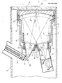
- FIG. 2 shows a construction of a charged particle energy analyzer applied for electron spectroscopy for chemical analysis (ESCA) according to the present invention. It may be evident that the charged particle energy analyzer of FIG. 2 is adapted for XPS, AES, and SIMS.
- ESA electron spectroscopy for chemical analysis
- the charged particle energy analyzer of FIG. 2 comprises an analyzer body 1, and inlet sleeve 2, an outlet sleeve 3, a first grid G1, a second grid G2, a third grid G3, a fourth grid G 4 , a fifth grid G5, and a sixth grid G 6 , a spheroid mirror 4, electrostatic shields 5, exhaustion ports 6, and an electron multiplier 7.
- the above-constructed analyzer is shielded by a magnetic shield 8.
- An X-ray gun 8 with an X-ray filter 9 is provided adjacent the analyzer.
- a sample 10 is disposed under the inlet sleeve 2, being adjacent the X-ray gun 8.
- the analyzer, the X-ray 8, and the sample 10 are disposed within a vacuum chamber 11 for vacuum pumping.
- the X-ray gun 8 is provided for irradiating the sample 10 with a beam of characteristic X-rays, so that the charged particle, in this case, are emitted from the sample 10. It may be possible that the X-ray gun 8 is replaced by an electron gun and an ion gun.
- the charged particles disperse toward the inlet sleeve 2.
- the outlet sleeve 3 receives the photoelectrons selected in accordance with the principle of the present invention by the grids.
- the spheroid mirror 4 has two focuses close to the central surface of the sample 10 and the central surface of the electron multiplier 7, which are symmetrical as the central axis of the mirror 4.
- the analyzer body 1 covers the analyzer, wholly.
- the third grid G 3 is disposed in front of the spheroid mirror 4, so that the grid G 3 is parallel with the mirror 4.
- the third grid G 3 and the spheroid mirror 4 form a low energy pass reflection filter.
- the first grid G 1 is provided for preventing performance decrease from static sample charging.
- the second grid G 2 is provided for making a retarding field.
- the first grid G 1 and the second grid G 2 are arranged at the inlet sleeve 2. These grids G 1 and G 2 are concentric with the center of the sample 10.
- the fourth grid G 4 , the fifth grid G 5 and the sixth grid G 6 are disposed at the outlet sleeve 3.
- the photo-electrons having high energy can pass through the fifth grid G 5 .
- the sixth grid G 6 is provided to accelerate the photoelectrons.
- the fourth grid G 4 , the fifth grid G 5 and the sixth grid G 6 are concentric with the center of the electron multiplier 7.
- the ring 12 is provided for supporting the third grid G 3 .
- the mirror 4 made from aluminum has a spheroidal reflection surface. On the surface of the mirror 4, carbon 14 is coated to have better conductivity and to reduce secondary electrons.
- the insulator 13 made from ceramic whose surface is coated with film having high resistivity is a guard ring provided for preventing field disturbance at the ends between the spheroid mirror 4 and the third grid G 3 , the first grid G 1 and the second grid G 2 , and the fourth grid G 4 and the fifth grid G 5 .
- the exhaustion ports 6 are provided through which air can be easily evacuated from the analyzer body 1.
- the electrostatic shield 5 is provided to prevent the field effect through the ports from the outer part.
- the electron multiplier 7 is provided for detecting the photoelectrons to measure the energy of them.
- the irradiated photoelectrons are received by the inlet sleeve 2.
- the respective parts have the following voltage.
- the photoelectrons transmitting the second grid G 2 go towards the third grid G 3 after straight passing through the above- stated apace.
- the spheroid mirror 4 is provided for selectively reflecting the photoelectrons. Since the absolute value of the voltage at the spheroid mirror 4 is more than that of the voltage at the third grid G 3 , namely, -(V A + Eo' + ) volt, the photoelectrons having the energy smaller than e(V +Eo+ ) are reflected by the mirror 4 and the photoelectrons having the energy larger than e(V A +Eo+ ) collide with the mirror 4 to thereby consume the energy.
- the analyzer pass energy Eo is referred to pass energy of the photoelectrons in the analyzer.
- the photo- electrons reflected by the spheroid mirror 4 can transmit the fourth grid G4 having the voltage of -V A .
- the fifth grid G 5 is provided for selectively transmitting the photoelectrons as the high energy pass transmission filter. Therefore, the photo- electrons having the energy smaller than e(V A +Eo- ) are reflected by the fifth grid G 5 and the photoelectrons having the energy larger than e(V A +Eo- ) pass the fifth grid G 5 .
- the sixth grid G 6 applied the voltage V D is provided for accelerating the photoelectrons.
- the photoelectrons are converged at the electron multiplier 7, the electrons having the energy larger than e(V A +Eo- ) as selected by the fifth grid G 5 and smaller than e(V A +Eo+ ) as selected by the spheroid mirror 4, namely, the electron multiplier detects the electrons having the band energye-dE.
- FIG. 3 shows a graph representing the voltages applied to the grids and the spheroid mirror 4 and the filter characteristic according to the present invention.
- the energy analysis are carried out by changing the value of V A to be applied to the second, third, and fourth grids G 2 , G 3 and G 4 while the voltages of the second, third, and fourth grids G 2 , G 3 and G 4 are made identical, and the voltage difference between the grids G 2 , G 3 , G 4 and the spheroid mirror 4, the third grid G 3 , the fifth grid G5 is constant.
- the photoelectrons passed through the fifth gridG5 are so slow, as to be zero electron volt.
- the sixth grid G 6 is provided for accelerating the photoelectron pass through the fifth grid G 5 .
- the sixth grid G 6 is needed between the fifth grid G S and the electron multiplier 7 for obtaining the good image, because the orbit of the electrons having very low energy are easily disturbed by the outer undesired electrostatic potential and magnetic field.
- the detector to obtain the information of the image is a position sensitive one such as a channel plate or the fluorescent screen followed by a video camera.
- the reflector is a spheroid mirror.
- a spherical mirror replaces the spheroid mirror 4 when the distance between the sample 10 and the multiplier 7 is enough small as compared with the distance between the mirror surface and the sample 10, and the distance between the mirror surface and the multiplier 7.
- FIG. 4 shows an enlarged view of a filter means such as the third grid G 3 and the spheroid mirror 4.
- an appearing reflection face is an spheroid face separated at the distance d from the spheroid mirror 4. Therefore, the focuses of the center of the spheroid mirror 4 and the detector 7 are not the focus of the spheroid mirror 4, but one of a spheroid face 4'.
- the spheroid mirror which has two complex focuses. On the two complex focuses, the sample and the electron multiplier are disposed. Therefore, the photoelectrons irradiated from the sample are introduced directly into the analyzer. In addition the sample, the X-ray gun,' and the electron multiplier are disposed outside the analyzer, so that the photoelectrons in the analyzer are not prevented from raying. The photoelectrons irradiated from the sample with wide solid angles are not lost.
- the system of the present invention provides high sensitivity concerning the photoelectrons as compared with:.the system of FIG. 1. Since the energy analyzing elements are gathered at one side of the curve surface of the reflected mirror, the size of the system of FIG. 2 can be half of that of system of FIG. 1.
Landscapes
- Chemical & Material Sciences (AREA)
- Analytical Chemistry (AREA)
- Analysing Materials By The Use Of Radiation (AREA)
- Electron Tubes For Measurement (AREA)
Priority Applications (2)
| Application Number | Priority Date | Filing Date | Title |
|---|---|---|---|
| EP19830102947 EP0120106B1 (de) | 1983-03-24 | 1983-03-24 | Energieanalysator für geladene Teilchen |
| DE8383102947T DE3377038D1 (en) | 1983-03-24 | 1983-03-24 | Charged particle energy analyzer |
Applications Claiming Priority (1)
| Application Number | Priority Date | Filing Date | Title |
|---|---|---|---|
| EP19830102947 EP0120106B1 (de) | 1983-03-24 | 1983-03-24 | Energieanalysator für geladene Teilchen |
Publications (2)
| Publication Number | Publication Date |
|---|---|
| EP0120106A1 true EP0120106A1 (de) | 1984-10-03 |
| EP0120106B1 EP0120106B1 (de) | 1988-06-08 |
Family
ID=8190371
Family Applications (1)
| Application Number | Title | Priority Date | Filing Date |
|---|---|---|---|
| EP19830102947 Expired EP0120106B1 (de) | 1983-03-24 | 1983-03-24 | Energieanalysator für geladene Teilchen |
Country Status (2)
| Country | Link |
|---|---|
| EP (1) | EP0120106B1 (de) |
| DE (1) | DE3377038D1 (de) |
Citations (1)
| Publication number | Priority date | Publication date | Assignee | Title |
|---|---|---|---|---|
| US3935454A (en) * | 1974-06-28 | 1976-01-27 | E. I. Du Pont De Nemours & Company | Electron collection in electron spectrometers |
-
1983
- 1983-03-24 EP EP19830102947 patent/EP0120106B1/de not_active Expired
- 1983-03-24 DE DE8383102947T patent/DE3377038D1/de not_active Expired
Patent Citations (1)
| Publication number | Priority date | Publication date | Assignee | Title |
|---|---|---|---|---|
| US3935454A (en) * | 1974-06-28 | 1976-01-27 | E. I. Du Pont De Nemours & Company | Electron collection in electron spectrometers |
Non-Patent Citations (1)
| Title |
|---|
| NUCLEAR INSTRUMENTS & METHODS, vol. 172, no. 1,2, May 1980, pages 327-336, Amsterdam, NL. * |
Also Published As
| Publication number | Publication date |
|---|---|
| EP0120106B1 (de) | 1988-06-08 |
| DE3377038D1 (en) | 1988-07-14 |
Similar Documents
| Publication | Publication Date | Title |
|---|---|---|
| Engel et al. | A UHV-compatible photoelectron emission microscope for applications in surface science | |
| CA1269181A (en) | Mass spectrometer for positive and negative ions | |
| EP0083465B1 (de) | Schlitztechnik-Röntgenaufnahme | |
| US4810879A (en) | Charged particle energy analyzer | |
| US3889115A (en) | Ion microanalyzer | |
| US5780859A (en) | Electrostatic-magnetic lens arrangement | |
| JP3266286B2 (ja) | 荷電粒子エネルギー分析器 | |
| US3937957A (en) | Apparatus for determining the energy of charged particles | |
| US5286974A (en) | Charged particle energy analyzers | |
| US4546254A (en) | Charged particle energy analyzer | |
| EP0120106A1 (de) | Energieanalysator für geladene Teilchen | |
| US4752685A (en) | Electronic spectrometer for identifying element conditions of a sample surface by utilizing an energy spectrum of charged particles | |
| EP0790634B1 (de) | Elektrostatisch-magnetische Linsenanordnung | |
| US4686417A (en) | X-ray image intensifier | |
| GB1601302A (en) | X-ray tube | |
| US4554457A (en) | Magnetic lens to rotate transverse particle momenta | |
| US4070574A (en) | Magnifying image intensifier | |
| US5962850A (en) | Large aperture particle detector with integrated antenna | |
| US2414881A (en) | Television transmitting tube with a concave secondary electron emitter | |
| US4857730A (en) | Apparatus and method for local chemical analyses at the surface of solid materials by spectroscopy of X photoelectrons | |
| US3478216A (en) | Image converter for detecting electromagnetic radiation especially in short wave lengths | |
| US3383514A (en) | Multi-stage image converter with both magnifying and minifying stages | |
| EP0084915B1 (de) | Fernsehkameraröhre | |
| US2897388A (en) | Directed ray tube and the like | |
| US2804560A (en) | Electronic device sensitive to invisible images |
Legal Events
| Date | Code | Title | Description |
|---|---|---|---|
| PUAI | Public reference made under article 153(3) epc to a published international application that has entered the european phase |
Free format text: ORIGINAL CODE: 0009012 |
|
| AK | Designated contracting states |
Designated state(s): DE FR GB SE |
|
| 17P | Request for examination filed |
Effective date: 19850315 |
|
| 17Q | First examination report despatched |
Effective date: 19860826 |
|
| GRAA | (expected) grant |
Free format text: ORIGINAL CODE: 0009210 |
|
| AK | Designated contracting states |
Kind code of ref document: B1 Designated state(s): DE FR GB SE |
|
| REF | Corresponds to: |
Ref document number: 3377038 Country of ref document: DE Date of ref document: 19880714 |
|
| ET | Fr: translation filed | ||
| RAP2 | Party data changed (patent owner data changed or rights of a patent transferred) |
Owner name: SHIMADZU CORPORATION |
|
| PLBE | No opposition filed within time limit |
Free format text: ORIGINAL CODE: 0009261 |
|
| STAA | Information on the status of an ep patent application or granted ep patent |
Free format text: STATUS: NO OPPOSITION FILED WITHIN TIME LIMIT |
|
| 26N | No opposition filed | ||
| PGFP | Annual fee paid to national office [announced via postgrant information from national office to epo] |
Ref country code: FR Payment date: 19930309 Year of fee payment: 11 |
|
| PGFP | Annual fee paid to national office [announced via postgrant information from national office to epo] |
Ref country code: GB Payment date: 19930312 Year of fee payment: 11 |
|
| PGFP | Annual fee paid to national office [announced via postgrant information from national office to epo] |
Ref country code: SE Payment date: 19930315 Year of fee payment: 11 |
|
| PGFP | Annual fee paid to national office [announced via postgrant information from national office to epo] |
Ref country code: DE Payment date: 19930324 Year of fee payment: 11 |
|
| PG25 | Lapsed in a contracting state [announced via postgrant information from national office to epo] |
Ref country code: GB Effective date: 19940324 |
|
| PG25 | Lapsed in a contracting state [announced via postgrant information from national office to epo] |
Ref country code: SE Free format text: LAPSE BECAUSE OF NON-PAYMENT OF DUE FEES Effective date: 19940325 |
|
| GBPC | Gb: european patent ceased through non-payment of renewal fee |
Effective date: 19940324 |
|
| PG25 | Lapsed in a contracting state [announced via postgrant information from national office to epo] |
Ref country code: FR Effective date: 19941130 |
|
| PG25 | Lapsed in a contracting state [announced via postgrant information from national office to epo] |
Ref country code: DE Effective date: 19941201 |
|
| REG | Reference to a national code |
Ref country code: FR Ref legal event code: ST |
|
| EUG | Se: european patent has lapsed |
Ref document number: 83102947.5 Effective date: 19941010 |