EP0120216A1 - Va et vient à pales pour machine à bobiner - Google Patents
Va et vient à pales pour machine à bobiner Download PDFInfo
- Publication number
- EP0120216A1 EP0120216A1 EP84100848A EP84100848A EP0120216A1 EP 0120216 A1 EP0120216 A1 EP 0120216A1 EP 84100848 A EP84100848 A EP 84100848A EP 84100848 A EP84100848 A EP 84100848A EP 0120216 A1 EP0120216 A1 EP 0120216A1
- Authority
- EP
- European Patent Office
- Prior art keywords
- thread
- guide
- traversing
- stroke
- traversing stroke
- Prior art date
- Legal status (The legal status is an assumption and is not a legal conclusion. Google has not performed a legal analysis and makes no representation as to the accuracy of the status listed.)
- Granted
Links
- 238000004804 winding Methods 0.000 title claims abstract description 28
- 230000008859 change Effects 0.000 claims description 4
- 230000000694 effects Effects 0.000 description 3
- 230000008901 benefit Effects 0.000 description 2
- 230000001133 acceleration Effects 0.000 description 1
- 230000001154 acute effect Effects 0.000 description 1
- 230000015572 biosynthetic process Effects 0.000 description 1
- 230000015556 catabolic process Effects 0.000 description 1
- 238000005352 clarification Methods 0.000 description 1
- 230000001419 dependent effect Effects 0.000 description 1
- 238000002474 experimental method Methods 0.000 description 1
- 230000006872 improvement Effects 0.000 description 1
- 230000003993 interaction Effects 0.000 description 1
- 239000000256 polyoxyethylene sorbitan monolaurate Substances 0.000 description 1
- 230000009467 reduction Effects 0.000 description 1
Images


Classifications
-
- B—PERFORMING OPERATIONS; TRANSPORTING
- B65—CONVEYING; PACKING; STORING; HANDLING THIN OR FILAMENTARY MATERIAL
- B65H—HANDLING THIN OR FILAMENTARY MATERIAL, e.g. SHEETS, WEBS, CABLES
- B65H54/00—Winding, coiling, or depositing filamentary material
- B65H54/02—Winding and traversing material on to reels, bobbins, tubes, or like package cores or formers
- B65H54/28—Traversing devices; Package-shaping arrangements
- B65H54/2836—Traversing devices; Package-shaping arrangements with a rotating guide for traversing the yarn
- B65H54/2839—Traversing devices; Package-shaping arrangements with a rotating guide for traversing the yarn counter rotating guides, e.g. wings
-
- B—PERFORMING OPERATIONS; TRANSPORTING
- B65—CONVEYING; PACKING; STORING; HANDLING THIN OR FILAMENTARY MATERIAL
- B65H—HANDLING THIN OR FILAMENTARY MATERIAL, e.g. SHEETS, WEBS, CABLES
- B65H2701/00—Handled material; Storage means
- B65H2701/30—Handled filamentary material
- B65H2701/31—Textiles threads or artificial strands of filaments
Definitions
- the invention relates to a winding machine for winding a thread into a cross-wound bobbin, with a traversing device, by means of which the thread is moved back and forth essentially transversely to its running direction over a traversing stroke H which essentially corresponds to the bobbin length, and the two rotors rotating in opposite directions with driving arms which run in two closely adjacent rotary planes (I, II) penetrated by the thread path and alternately guide the thread with its thread guide edges along a fixed thread guide between the traverse ends.
- Winding machines with wing traversing are known from e.g. US-PS 3, 650,487, US-PS 3,3374,961, CH-PS 448 835, DE-OS 32 43 985 (Bag. 1272).
- the wings in the context of this application also: driver arms
- a further guide edge referred to in this application as a brake flag or guide flag
- the precise handover of the thread also serves the measure described in DE-OS 32 43 985 that the wings on their side facing away from the thread guide edge (pushing edge) have a guide edge referred to in this application as a brake flag or guide flag, which is shaped in such a way that their point of intersection with the ruler moves essentially at the traversing speed in the direction of the traversing stroke center. This prevents the thread from moving faster to the center of the traversing stroke than corresponds to the guide speed of the pushing edge of the wing traveling to the center of the traversing stroke.
- the accuracy of the thread guide is particularly in the end regions of the traverse stroke, i.e. the precise transfer from one driver arm to the other and the precise takeover of the thread guide by this other driver arm are improved in that the guide ruler is at least partially designed as a positive guide. In these restricted guidance areas, the guide ruler has a front and a rear guide rail. In this way, the inadmissible lifting of the thread from the guide rule or the thread guide edge of the driver arms is avoided. This is particularly advantageous at the traversing stroke ends if the thread is to be laid there with increased accelerations and / or decelerations in accordance with a laying law. Such relocation laws are e.g. described in DE-PS 20 40 479.
- the invention is particularly advantageous if it is used in conjunction with the use of the so-called guiding flags.
- the guide vanes of the transferring driving arms cover the slot formed between the guide rails of the guide ruler according to a predetermined geometry and form with it a positive guide for the thread, which moves with a predetermined law of motion to the center of the traversing stroke.
- this positive guidance can form a narrow passage adapted to the thread diameter.
- the slot between the two guide rails on the one hand and the thread-guiding gusset between the thread guide edge of the receiving driving arm and the guide vane of the transferring driving arm - as seen in the thread direction - do not overlap. This ensures that the thread is deflected between the one part of the positive guidance, namely the guide rails of the guide rail and the other part of the positive guidance, namely the gusset between the pushing edge of the receiving arm and the guide vane of the transferring driving arm. This ensures that any uncontrolled movement is removed from the positively guided thread.
- the guide rails, on the one hand, and the guide vanes, on the other hand are designed in such a way that the deflection of the thread between these parts of the positive guidance means that the changes in the thread length in the traversing triangle caused by the traversing and in particular by the reversal of the traversing movement and the thereby in the course of the traversing stroke and in particular at the traversing stroke ends otherwise occurring thread tension fluctuations.
- the particular advantage of this embodiment is that one can specifically compensate for the thread tension fluctuations of the return stroke, that is to say during and after the reversal of the traversing movement, in particular increase the thread tension without at the same time influencing the thread tension of the forward stroke, that is to say before the stroke reversal. This is possible above all if the guide rails of the thread guide rule do not overlap, ie essentially to form a guide slot which is open in the thread direction.
- the guide vane so that it takes over its thread guiding function only at a short distance from the end of the traversing stroke. It is thereby achieved that the transferring wing leaving the traversing stroke first releases the thread guide before the take-over wing entering the traversing stroke has taken over the thread guide.
- This enables the thread to move under its own pulling force over the specified short distance from the end of the traversing stroke in the direction of the traversing center (the thread returns).
- the take-over driving arm entering the traversing stroke protrudes with its pushing edge so far below the thread guide that it can safely take over the thread guide. depending on the size of the thread pulling force, there would be the danger that the thread would be overtaken by the driver arm taking over into the traversing stroke and would no longer be gripped.
- the proposed measure can increase the reliability of the thread takeover at the traversing stroke ends in such a way that it is also possible to mount the rotors concentrically, which without the measures according to the invention leads to the inoperability of the wing traversing.
- the improvement of the thread transfer and thread takeover can also be achieved according to the invention in that braking forces are exerted on the thread by the guide rails forming the positive guide.
- the guide rails are arranged in a plane that coincides with the general thread running direction or forms an acute angle. The result is that the thread wraps around the guide rails over a certain angle and is braked both in its running direction and in its traversing direction.
- the tendency to jump back i.e. the tendency of the thread to move automatically and faster than the receiving driving arm in the direction of the center of the traversing stroke is reduced and, moreover, the reduction in the thread pulling force occurring in the stroke reversal areas is compensated for.
- the offset of the guide rails ie the inclination of the plane in which the two guide rails are arranged, changes in the course of the traversing stroke, so that the wrap angle of the thread on the guide rails also changes.
- a braking effect which is variable with the traversing movement is achieved, which on the one hand can be adapted to the tendency of the thread to bounce back and, on the other hand, the tendency to change the thread tension.
- the braking effect is an excellent means of constantly increasing the thread tension over the traversing stroke hold and produce coils with uniform coil hardness over their length.
- the deflection on the guide rails over a short distance immediately following the traversing stroke end is canceled or at least reduced in such a way that there is no decisive obstacle to the tendency of the thread to spring back over this short distance. Over this short distance, the return of the thread from the end of the stroke towards the center of the stroke is permitted. This measure also increases the reliability of the transfer of the thread from one to the other driving arm and enables the rotors to be supported concentrically.
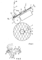
- the winding machine shown in cross section in FIG. 1 has, as essential components, the winding spindle 1 and the traversing device 2.
- the winding spindle is driven in the direction of rotation 4 by a motor, not shown, connected to the winding spindle 1.
- Sleeves 5 are clamped in alignment on the winding spindle.
- a cross-wound bobbin 6 is formed on each sleeve 5 from a thread 3 starting from a vertical direction.
- a winding spindle can typically run three or four or six or eight threads parallel to one another and can be wound up to a corresponding number of bobbins 6 for all identical winding times (winding travel).
- the traversing device consists of two rotors with a plurality of rotating blades 7 and 8, which are arranged in two planes of rotation I and II. In front of these wings is a guide ruler 9, along which the thread slides as it traverses.
- the guide ruler has the guide rail 9.1 on one side and the guide rail 9.2 (shown in dashed lines) on the other side of the thread running plane.
- the planes of rotation I, II and plane III, in which the guide ruler 9 is arranged, are inclined such that the planes of rotation form an angle alpha between 45 ° and 70 ° with the thread feed direction indicated by arrow 10. This ensures that a guide roller 11 can be attached at a very short distance below the plane of rotation II.
- the thread is guided onto the respective bobbin 6 in contact with this guide roller.
- the guide roller 11 is in circumferential contact on the coil 6.
- the guide roller 11 can also be at a short distance from the surface of the coil and can be driven to rotate.
- each traversing device which rotate in the plane of rotation I, sit on the rotor 12.
- its hollow shaft 16 can not only be eccentric but also be mounted concentrically to the shaft 15 of the rotor 12.
- the rotors of the stroke range shown are driven in opposite directions of rotation, at the same speed and in a specific phase position by a drive (not shown) via a gear 22. Further details result from the prior art and the application EU-84100433.6 (Bag 1321).
- Fig. 2 shows an inventive design of the guide 9, with the guide rail 9.1, which is on the same side of the thread as the traversing and the guide rail 9.2. on the opposite side.
- the guide ruler is provided with thread catch notches 33 outside the traversing area.
- the guideline can be moved away from the rotors. As a result, the thread is pushed away from the area of rotation of the wings, as shown in dashed lines. The thread then slides to one or the other side of the lifting area and falls into one of the thread catching notches 33 arranged on both sides of the lifting area.
- the guide rails 9.1 and 9.2 form a positive guidance of the thread in the traversing stroke end regions, the advantage of which is, on the one hand, that the guide ruler in this embodiment can also be used to lift the thread from the traversing device and to reinsert the thread into the traversing device.
- the positive guidance by the guide rails 9.1 and 9.2 also ensures a safe guidance of the thread on the guides of the driving arms 7 and 8. It can be prevented in particular with this positive guidance that the driving arm 7 entering the traversing stroke takes over the thread - as long as it just a short distance beyond the leading edge 9.1 - loses the thread.
- the slot formed between the guide rails 9.1 and 9.2 can be made correspondingly narrow.
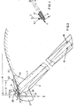
- 3 and 4 illustrate on the one hand the interaction of the positive guidance and the guide vanes of the driver arms, on the other hand the targeted deflection of the thread on the positive guide elements, namely the guide rails of the guide rail on the one hand and the thread guide edges of the driver arms on the other hand.
- the entire front end of the wings 7 and 8 shown forms a thread guide edge.
- the parts of the thread guide edge pointing in the oscillating movement 27 or 28 are referred to as thrust edge 26 and the part facing away from it is referred to as guide flag or brake flag 21.
- the traversing device consists of a pair of rotors with two-, three-, or four-armed blades, of which only one arm 7 or 8 is shown.
- a traversing device according to the invention can each consist of a pair of one-armed rotors in the traversing stroke end regions and any other type of traversing device in the central region.
- the associated rotors are rotatable about the axes 18, 19 and eccentrically mounted to one another and driven in opposite directions of rotation.
- the guide rail 9.1 of the guide ruler extends over the entire traversing stroke H and is on the bearing side of the rotors.
- the guide rail 9.2 is designed as a wire bracket and lies on the opposite side of the thread run. This wire bracket 9.2 extends in the exemplary embodiment only over a region B of the traversing stroke end.
- the wire bracket 9.2 is bent so that it covers the guide rail 9.1 - in the vertical view shown on planes I, II, III according to FIG. 4- according to a predetermined, empirically determined and dependent on the measured thread tension - negative and positive .
- FIG. 4 shows a section through an area of positive overlap.
- This positive overlap means that the thread on the guide rails 9.2 and 9.1 is deflected with a certain wrap angle. Furthermore, the thread between the positive guide slot, which is formed between the guide rails 9.1 and 9.2, on the one hand, and the gusset 14, which is formed by the pushing edge 26 of the wing 7 conveying into the traversing stroke and the guide vane 21 of the wing 8 extending from the traversing stroke, on the other hand tense and redirected.
- These deflections and tensions are designed so that predetermined braking forces are exerted on the thread, which are effective both in the thread running direction and in the traversing direction.
- the braking forces serve to fluctuate the thread tension to compensate force that occur during the traversing movement over a traversing stroke. These fluctuations are based in the reversal areas on the one hand on dynamic effects, but on the other hand on the fact that in the reversal areas the carryover direction with which the thread between the traversing device and the bobbin is carried (runs) reverses.
- the braking forces should be so great that the thread does not make any uncontrolled movements in the direction of the center of the stroke (return) caused by its thread pulling forces. The deflection and tensioning of the thread between the guide rails and the pushing edge or guide vane of the wing only occurs after the stroke has been reversed.
- FIG. 5 shows a similar embodiment in top view, the rotors of which, however, are mounted concentrically in the common axis 20, but are also driven in opposite directions. Otherwise, this exemplary embodiment corresponds to the exemplary embodiment according to FIG. 3 and FIG. 4, the deviation being the special design of the guide vanes 21.
- the wings 7 and 8 have an area 17 following their thrust curve 26, which is designed such that it disappears together with the thrust edge 26 behind the guide rail 9.1 of the thread guide ruler - as viewed in the direction of thread travel - so that the thread when he comes free from the pushing edge 26, is guided for a brief moment until the area of the guide vane 21 adjoining the area 17 appears above the thread guide or the guide rail 9.1, covers the slot between the guide rails 9.1 and 9.2 and in this way and Form again a positive guide for the thread.
- the yarn and the guide rail 9.2 is given the opportunity of the recess, particularly in the distance from the guide rail 9.1 has a negative overlap.
- the recess is therefore used deliberately to give the wing 8 entering the traversing stroke the opportunity to emerge above the guide rail 9.1 with a sufficient length of its pushing edge and to form a secure positive guidance for the thread.
- Fig. 6 the thread guide 9 and end pieces of the driver arms 7 and 8 are shown in a top region of the traversing stroke H, the direction of rotation arrows being designated 27 and 28.
- the driver arms 7 and 8 are shown at a point in time which is shortly after the point in time at which the thread has reached the end of the traversing stroke, that is to say shortly after the point in time at which the pushing edge 26 of the wing which moves out of the traversing stroke and transfers the thread 8 dipped under the ruler and released the thread.
- the front tip of the pushing edge 26 of the wing 7 entering the traversing stroke was just about to emerge above the guide ruler. Therefore, there was no defined guidance of the thread 3 at the end of the traversing stroke.
- the thread 3 could, due to its thread tensile force and the tension in the traversing triangle, spring back in the direction of arrow 23 from the traversing stroke end to the short distance E, that is, the one shown in FIG. 6 Execute position.
- the brake vane 21 of the wing 8 leaving the traversing stroke appears above the guide ruler and thereby stops the thread 3, so that the thread only has a speed defined by the shape of the brake vane 21 corresponding to the movement of the gusset, which is formed between the guide ruler 9 and the guide vane 21, can move in the direction of the center of the traversing stroke.
- the wing 7 entering the traversing stroke is given time with its pushing edge 26 to emerge above the guide ruler and with a guide length which ensures reliable thread guidance before it has caught up with the thread. It is thus possible to mount the two vanes 7 and 8 or their rotors concentrically with one another.
- the positive guidance of the thread between the guide rails 9.1 and 9.2 is designed in such a way that there is a short distance E at the end of the traversing stroke, in which the guide rails 9.1, 9.2 do not overlap or only overlap slightly in the thread running direction than in the remaining end region B of the traversing stroke.
- the thread can thus make an unobstructed or only slightly hindered return from the end of the stroke in the direction of the center of the stroke.
- the return movement is braked so that the pushing edge 26 of the driving arm 7 entering the traversing stroke, which emerges above the guide rail 9.1, can pull in the thread and take over the guide rail 9.1 with a sufficiently long guide length.
- the thread is again forced through the push edge 26 of the driving arm 7. Due to the variable overlap between the guide rails 9.1 and 9.2 in the course of the further traversing stroke, the thread is deflected and tensioned with variable intensity.
- the overlap between the guide rails 9.1 and 9.2 is designed in such a way that the expected changes in the thread tensile forces in the end region of the traversing stroke H are compensated for as completely as possible.
- the exact course of the overlap depends on the respective geometric conditions and the thread running speeds and traversing speeds and can be determined in the first approximation by calculation, but with accuracy only by experiment.
Landscapes
- Engineering & Computer Science (AREA)
- Textile Engineering (AREA)
- Winding Filamentary Materials (AREA)
- Guides For Winding Or Rewinding, Or Guides For Filamentary Materials (AREA)
Applications Claiming Priority (2)
| Application Number | Priority Date | Filing Date | Title |
|---|---|---|---|
| DE3302805 | 1983-01-28 | ||
| DE3302805 | 1983-01-28 |
Publications (2)
| Publication Number | Publication Date |
|---|---|
| EP0120216A1 true EP0120216A1 (fr) | 1984-10-03 |
| EP0120216B1 EP0120216B1 (fr) | 1986-10-29 |
Family
ID=6189412
Family Applications (1)
| Application Number | Title | Priority Date | Filing Date |
|---|---|---|---|
| EP84100848A Expired EP0120216B1 (fr) | 1983-01-28 | 1984-01-27 | Va et vient à pales pour machine à bobiner |
Country Status (3)
| Country | Link |
|---|---|
| US (1) | US4561603A (fr) |
| EP (1) | EP0120216B1 (fr) |
| DE (1) | DE3461067D1 (fr) |
Cited By (4)
| Publication number | Priority date | Publication date | Assignee | Title |
|---|---|---|---|---|
| DE3404303A1 (de) * | 1984-02-08 | 1985-08-08 | Barmag Barmer Maschinenfabrik Ag, 5630 Remscheid | Aufspulmaschine |
| DE3627879A1 (de) * | 1986-08-16 | 1988-02-25 | Barmag Barmer Maschf | Verfahren zum aufwickeln von faeden |
| DE3803286A1 (de) * | 1987-02-11 | 1988-08-25 | Barmag Barmer Maschf | Aufspulmaschine |
| US5624081A (en) * | 1992-12-23 | 1997-04-29 | Barmag Ag | Yarn winding apparatus |
Families Citing this family (9)
| Publication number | Priority date | Publication date | Assignee | Title |
|---|---|---|---|---|
| DE3417457A1 (de) * | 1984-05-11 | 1985-11-14 | Barmag Barmer Maschinenfabrik Ag, 5630 Remscheid | Aufspulmaschine |
| DE3761556D1 (de) * | 1986-08-09 | 1990-03-08 | Barmag Barmer Maschf | Verfahren zum aufwickeln von faeden. |
| US4993650A (en) * | 1988-11-07 | 1991-02-19 | Appalachian Electronic Instruments, Inc. | High speed precision yarn winding system |
| US4989798A (en) * | 1988-11-07 | 1991-02-05 | Appalachian Electronic Instruments, Inc. | High speed precision yarn winding system |
| US5282582A (en) * | 1989-04-28 | 1994-02-01 | Teijin Seiki Co., Ltd. | Yarn traversing apparatus |
| MX9307832A (es) * | 1992-12-23 | 1995-01-31 | Barmag Barmer Maschf | Maquina para devanar. |
| DE4317087A1 (de) * | 1993-05-21 | 1994-11-24 | Neumag Gmbh | Vorrichtung zum Aufwickeln von Fäden |
| EP0873275B1 (fr) * | 1996-10-12 | 2002-07-17 | B a r m a g AG | Machine de bobinage pour fil arrivant en continu |
| DE19845325A1 (de) * | 1997-10-10 | 1999-04-15 | Barmag Barmer Maschf | Aufspulmaschine |
Citations (4)
| Publication number | Priority date | Publication date | Assignee | Title |
|---|---|---|---|---|
| CH424571A (de) * | 1964-01-27 | 1966-11-15 | Toshiba Machine Co Ltd | Fadenführvorrichtung |
| FR1541176A (fr) * | 1967-09-18 | 1968-10-04 | Plutte | Guide-fil pour bobinoirs et canetières |
| GB1168893A (en) * | 1966-08-19 | 1969-10-29 | Jakob Schaerer | Improvements in Winding Apparatus |
| DE3243985A1 (de) * | 1981-12-03 | 1983-06-16 | Barmag Barmer Maschinenfabrik Ag, 5630 Remscheid | Changiereinrichtung |
Family Cites Families (2)
| Publication number | Priority date | Publication date | Assignee | Title |
|---|---|---|---|---|
| US3650486A (en) * | 1968-05-20 | 1972-03-21 | Toray Industries | Yarn traversing method and apparatus of a rotary blade type |
| GB1595971A (en) * | 1977-03-04 | 1981-08-19 | Mackie & Sons Ltd J | Yarn winder |
-
1984
- 1984-01-27 DE DE8484100848T patent/DE3461067D1/de not_active Expired
- 1984-01-27 EP EP84100848A patent/EP0120216B1/fr not_active Expired
-
1985
- 1985-01-25 US US06/694,952 patent/US4561603A/en not_active Expired - Fee Related
Patent Citations (4)
| Publication number | Priority date | Publication date | Assignee | Title |
|---|---|---|---|---|
| CH424571A (de) * | 1964-01-27 | 1966-11-15 | Toshiba Machine Co Ltd | Fadenführvorrichtung |
| GB1168893A (en) * | 1966-08-19 | 1969-10-29 | Jakob Schaerer | Improvements in Winding Apparatus |
| FR1541176A (fr) * | 1967-09-18 | 1968-10-04 | Plutte | Guide-fil pour bobinoirs et canetières |
| DE3243985A1 (de) * | 1981-12-03 | 1983-06-16 | Barmag Barmer Maschinenfabrik Ag, 5630 Remscheid | Changiereinrichtung |
Cited By (4)
| Publication number | Priority date | Publication date | Assignee | Title |
|---|---|---|---|---|
| DE3404303A1 (de) * | 1984-02-08 | 1985-08-08 | Barmag Barmer Maschinenfabrik Ag, 5630 Remscheid | Aufspulmaschine |
| DE3627879A1 (de) * | 1986-08-16 | 1988-02-25 | Barmag Barmer Maschf | Verfahren zum aufwickeln von faeden |
| DE3803286A1 (de) * | 1987-02-11 | 1988-08-25 | Barmag Barmer Maschf | Aufspulmaschine |
| US5624081A (en) * | 1992-12-23 | 1997-04-29 | Barmag Ag | Yarn winding apparatus |
Also Published As
| Publication number | Publication date |
|---|---|
| DE3461067D1 (en) | 1986-12-04 |
| EP0120216B1 (fr) | 1986-10-29 |
| US4561603A (en) | 1985-12-31 |
Similar Documents
| Publication | Publication Date | Title |
|---|---|---|
| EP0114642B1 (fr) | Machine à bobiner | |
| EP0120216B1 (fr) | Va et vient à pales pour machine à bobiner | |
| DE3505188C2 (de) | Fadentraversiervorrichtung für eine Kreuzspulen herstellende Maschine | |
| EP3571148B1 (fr) | Bobineuse | |
| DE3345237A1 (de) | Aufspulmaschine | |
| DE3417457C2 (fr) | ||
| EP0114641B1 (fr) | Machine à bobiner avec guide-fil à pales | |
| DE2808721A1 (de) | Garnwickler | |
| DE3703731A1 (de) | Aufspulmaschine mit fluegelchangierung | |
| EP0166292A1 (fr) | Va et vient pour bobinoir | |
| EP0677019A1 (fr) | Dispositif d'embobinage. | |
| CH650223A5 (de) | Vorrichtung zum steuern der fadenspannung zwischen einer changiervorrichtung und einer fadenspule. | |
| DE69013967T2 (de) | Ueberführungsapparat für Faden. | |
| DE2406641A1 (de) | Aufwickelvorrichtung mit automatischem wechsel von huelsen | |
| DE3302962A1 (de) | Aufspulmaschine | |
| DE10343315A1 (de) | Vorrichtung zum Aufspulen eines Fadens auf eine Kreuzspule | |
| EP0873276B1 (fr) | Bobineuse | |
| DE3243985A1 (de) | Changiereinrichtung | |
| DE3404303A1 (de) | Aufspulmaschine | |
| EP0752385B1 (fr) | Méthode et dispositif de va-et-vient pour des matériaux filiforms ou des rubans | |
| DE3901278A1 (de) | Vorrichtung zum herstellen einer kreuzspule | |
| DE3307915A1 (de) | Aufspulmaschine | |
| DE19750737A1 (de) | Changiereinrichtung | |
| DE8302278U1 (de) | Aufspulmaschine | |
| DE4315912C2 (de) | Aufspulmaschine |
Legal Events
| Date | Code | Title | Description |
|---|---|---|---|
| PUAI | Public reference made under article 153(3) epc to a published international application that has entered the european phase |
Free format text: ORIGINAL CODE: 0009012 |
|
| AK | Designated contracting states |
Designated state(s): BE CH DE FR GB IT LI NL |
|
| 17P | Request for examination filed |
Effective date: 19841019 |
|
| ITF | It: translation for a ep patent filed | ||
| GRAA | (expected) grant |
Free format text: ORIGINAL CODE: 0009210 |
|
| AK | Designated contracting states |
Kind code of ref document: B1 Designated state(s): BE CH DE FR GB IT LI NL |
|
| PG25 | Lapsed in a contracting state [announced via postgrant information from national office to epo] |
Ref country code: NL Effective date: 19861029 Ref country code: BE Effective date: 19861029 |
|
| REF | Corresponds to: |
Ref document number: 3461067 Country of ref document: DE Date of ref document: 19861204 |
|
| ET | Fr: translation filed | ||
| NLV1 | Nl: lapsed or annulled due to failure to fulfill the requirements of art. 29p and 29m of the patents act | ||
| PLBE | No opposition filed within time limit |
Free format text: ORIGINAL CODE: 0009261 |
|
| STAA | Information on the status of an ep patent application or granted ep patent |
Free format text: STATUS: NO OPPOSITION FILED WITHIN TIME LIMIT |
|
| 26N | No opposition filed | ||
| ITTA | It: last paid annual fee | ||
| PGFP | Annual fee paid to national office [announced via postgrant information from national office to epo] |
Ref country code: FR Payment date: 19951229 Year of fee payment: 13 |
|
| PGFP | Annual fee paid to national office [announced via postgrant information from national office to epo] |
Ref country code: GB Payment date: 19960118 Year of fee payment: 13 |
|
| PGFP | Annual fee paid to national office [announced via postgrant information from national office to epo] |
Ref country code: CH Payment date: 19960304 Year of fee payment: 13 |
|
| PG25 | Lapsed in a contracting state [announced via postgrant information from national office to epo] |
Ref country code: GB Effective date: 19970127 |
|
| PG25 | Lapsed in a contracting state [announced via postgrant information from national office to epo] |
Ref country code: CH Effective date: 19970131 Ref country code: LI Effective date: 19970131 |
|
| PGFP | Annual fee paid to national office [announced via postgrant information from national office to epo] |
Ref country code: DE Payment date: 19970226 Year of fee payment: 14 |
|
| REG | Reference to a national code |
Ref country code: CH Ref legal event code: PL |
|
| GBPC | Gb: european patent ceased through non-payment of renewal fee |
Effective date: 19970127 |
|
| PG25 | Lapsed in a contracting state [announced via postgrant information from national office to epo] |
Ref country code: FR Effective date: 19970930 |
|
| REG | Reference to a national code |
Ref country code: FR Ref legal event code: ST |
|
| PG25 | Lapsed in a contracting state [announced via postgrant information from national office to epo] |
Ref country code: DE Free format text: LAPSE BECAUSE OF NON-PAYMENT OF DUE FEES Effective date: 19981001 |