EP0120246A1 - Machine à cisailler - Google Patents
Machine à cisailler Download PDFInfo
- Publication number
- EP0120246A1 EP0120246A1 EP19840101319 EP84101319A EP0120246A1 EP 0120246 A1 EP0120246 A1 EP 0120246A1 EP 19840101319 EP19840101319 EP 19840101319 EP 84101319 A EP84101319 A EP 84101319A EP 0120246 A1 EP0120246 A1 EP 0120246A1
- Authority
- EP
- European Patent Office
- Prior art keywords
- cylinder
- crosshead
- knife carriage
- split ring
- ring
- Prior art date
- Legal status (The legal status is an assumption and is not a legal conclusion. Google has not performed a legal analysis and makes no representation as to the accuracy of the status listed.)
- Granted
Links
- 238000010008 shearing Methods 0.000 title description 5
- 238000000034 method Methods 0.000 description 4
- 230000036316 preload Effects 0.000 description 4
- 230000008439 repair process Effects 0.000 description 2
- 230000004323 axial length Effects 0.000 description 1
- 230000015556 catabolic process Effects 0.000 description 1
- 238000010276 construction Methods 0.000 description 1
- 238000005520 cutting process Methods 0.000 description 1
- 238000003780 insertion Methods 0.000 description 1
- 230000037431 insertion Effects 0.000 description 1
- 230000004048 modification Effects 0.000 description 1
- 238000012986 modification Methods 0.000 description 1
- 238000003466 welding Methods 0.000 description 1
Images

Classifications
-
- B—PERFORMING OPERATIONS; TRANSPORTING
- B23—MACHINE TOOLS; METAL-WORKING NOT OTHERWISE PROVIDED FOR
- B23D—PLANING; SLOTTING; SHEARING; BROACHING; SAWING; FILING; SCRAPING; LIKE OPERATIONS FOR WORKING METAL BY REMOVING MATERIAL, NOT OTHERWISE PROVIDED FOR
- B23D35/00—Tools for shearing machines or shearing devices; Holders or chucks for shearing tools
-
- B—PERFORMING OPERATIONS; TRANSPORTING
- B23—MACHINE TOOLS; METAL-WORKING NOT OTHERWISE PROVIDED FOR
- B23D—PLANING; SLOTTING; SHEARING; BROACHING; SAWING; FILING; SCRAPING; LIKE OPERATIONS FOR WORKING METAL BY REMOVING MATERIAL, NOT OTHERWISE PROVIDED FOR
- B23D15/00—Shearing machines or shearing devices cutting by blades which move parallel to themselves
-
- F—MECHANICAL ENGINEERING; LIGHTING; HEATING; WEAPONS; BLASTING
- F16—ENGINEERING ELEMENTS AND UNITS; GENERAL MEASURES FOR PRODUCING AND MAINTAINING EFFECTIVE FUNCTIONING OF MACHINES OR INSTALLATIONS; THERMAL INSULATION IN GENERAL
- F16B—DEVICES FOR FASTENING OR SECURING CONSTRUCTIONAL ELEMENTS OR MACHINE PARTS TOGETHER, e.g. NAILS, BOLTS, CIRCLIPS, CLAMPS, CLIPS OR WEDGES; JOINTS OR JOINTING
- F16B2200/00—Constructional details of connections not covered for in other groups of this subclass
- F16B2200/40—Clamping arrangements where clamping parts are received in recesses of elements to be connected
- F16B2200/406—Clamping parts being collars, bushings or wedges
-
- Y—GENERAL TAGGING OF NEW TECHNOLOGICAL DEVELOPMENTS; GENERAL TAGGING OF CROSS-SECTIONAL TECHNOLOGIES SPANNING OVER SEVERAL SECTIONS OF THE IPC; TECHNICAL SUBJECTS COVERED BY FORMER USPC CROSS-REFERENCE ART COLLECTIONS [XRACs] AND DIGESTS
- Y10—TECHNICAL SUBJECTS COVERED BY FORMER USPC
- Y10T—TECHNICAL SUBJECTS COVERED BY FORMER US CLASSIFICATION
- Y10T83/00—Cutting
- Y10T83/929—Tool or tool with support
- Y10T83/9457—Joint or connection
- Y10T83/9473—For rectilinearly reciprocating tool
Definitions
- the invention relates to a pair of scissors for material of any kind, for example scrap, rubble, rubbish, billets, strands and the like, with a knife carriage guided in a closed frame and possibly holding-down device and an associated one each, from a frame hole in a bore on the cylinder side.
- Crosshead pre-tensioned cylinder-piston arrangement existing drive.
- two drive cylinders are usually housed next to each other, one of which is connected to the main knife by its piston and the other forms the drive for the so-called hold-down device, which holds down or fixes the material to be cut during the cutting process .
- the cylinder associated with the hold-down device is considerably smaller than the other drive, referred to as the shear cylinder, because of the lower force to be applied. In principle, apart from the size, the cylinders do not differ. The following description therefore applies equally to the shear cylinder and the hold-down cylinder, even if only the shear cylinder is mentioned.
- the cylinders fixed in the crosshead are exposed to two forces running in their axial direction. Usually only the weight of the drive units and accessories are effective. This is taken up by a shoulder running around the cylinder from the edge of the bore in the crosshead.
- a threaded ring is used to intercept the substantially larger shear force acting from the bottom upwards, which after the cylinder has been inserted into the cross main bore pushed onto the cylinder from below and. is screwed onto an existing thread. The considerable shear forces are thus transferred from the cylinder via the thread and the threaded ring to the crosshead. To rule out any play in the cylinder axis direction between the cylinder and crosshead and to prevent the threaded ring from loosening, it is held under tension with a clamping system.
- the invention has for its object to provide a less sensitive attachment for the cylinder in question and to simplify the assembly and disassembly of the shear cylinder and / or ramming cylinder of a suitable material for any type, in particular scrap, scissors with at least the same operational reliability and service life.
- the solution according to the invention in the case of the scissors mentioned at the outset is that each cylinder fixed in the crosshead is opposed to forces directed from the knife carriage to the crosshead by a partially divided ring engaging in a circumferential recess in the cylinder surface and at least partially in the transverse main side facing the knife carriage the knife carriage facing side of the crosshead is firmly supported and that the cylinder is fastened on the side of the crosshead facing away from the knife carriage under pretension in its end position.
- the cylinder is preferably supported on the side of the crosshead facing away from the knife carriage by means of a threaded ring screwed onto the cylinder circumference or a second split ring engaging in a further circumferential recess in the cylinder surface.
- the invention consists in principle in the place of the thread previously accommodating the threaded ring in the outer surface of the cylinder in an annular circumferential recess or groove and to replace the threaded ring provided with the centering lug by a threadless, first split, in particular split, ring , which is fitted into the recess and for absorbing the reaction forces during shearing with its end face facing the crosshead protrudes sufficiently far radially outward beyond the edge of the bore receiving the shear cylinder and with its end face facing the knife carriage on the shoulder delimiting the recess or the collar thus formed is supported at the end of the cylinder.
- the recess must therefore be cut so deep that the adjoining collar of the cylinder can absorb the entire shear force. With the invention it is thus achieved that the shoulder of the recess or the adjoining collar of the cylinder replaces the thread previously necessary at this point.
- the associated recess is made in the cylinder surface in such a way that in the fixed cylinder position it extends at least partially into the bore of the crosshead.
- a circumferential recess can also be provided, which receives the parts of the split ring which protrude radially beyond the cylinder surface, so that the crosshead bore is quasi stepped.
- the first split ring can also be completely sunk in the crosshead in the prestressed position of the cylinder.
- the first split ring preferably has at least one centering projection which extends into the bore and whose maximum diameter is equal to the diameter of the cylinder. It is then sufficient to dimension the recess in the cylinder surface so that the centering projection extends into the cross-main bore when the cylinder is preloaded.
- a threaded ring which is screwed onto a thread on the cylinder circumference on the side of the crosshead facing away from the knife carriage, is preferably used to hold the cylinder weight and to pretension the cylinder against the abutment formed from the first divided ring.
- This threaded ring can lie flat with its end face on the crosshead in the region of the circumference of the bore receiving the cylinder. Since the threaded ring on this side of the crosshead has to absorb significantly lower forces than the threaded ring previously provided on the side of the crosshead facing the knife carriage, it can be designed correspondingly weaker. Centering in the area of this threaded ring is achieved by a fit on the cylinder circumference corresponding to the bore. Instead of such a fit on the cylinder circumference, a centering projection of the threaded ring projecting into the bore of the crosshead can also take place.
- the pre-tensioning end fastening of the cylinder on the side of the crosshead facing away from the knife carriage can be formed by the aforementioned second split ring.
- the This second split ring can also engage in a circumferential recess in the cylinder surface.
- the second split ring is preferably held together with the aid of a one-piece bandage ring.
- the assembly of the second split ring should be carried out under preload pressure using radially driven wedges.
- the wedges are expediently fixed with the aid of a weld seam to prevent loosening or loosening. Since the connection according to the invention cannot be loosened when properly installed, there is no need for re-tensioning and the welding of the wedges is not a disadvantage.
- the respective cylinder is inserted according to the invention from above into the bore provided in the crosshead.
- the abutment formed, for example, as a threaded ring on the top of the crosshead is screwed up from the final position to such an extent that the split ring on the underside of the crosshead can be inserted into the recess provided on the cylinder surface without any problems.
- the cylinder is then first, e.g. with the crane used for insertion, slightly raised, so that the threaded ring on the top of the crosshead can be temporarily tightened.
- the split ring partially gets into the bore or into a circumferential recess provided on the bore surface during this slight tightening of the threaded ring, so that it is fixed in any case in the radial direction.
- the split ring cannot be moved in the axial direction, since its axial length must be matched exactly to the recess.
- the cylinder is connected to its pressure feed lines and pressurized so that the knife carriage coupled to the cylinder piston of the scissors is extended to a stop.
- the knife carriage is pressed against the stop with maximum force, so that the split ring is pushed upwards and the threaded ring provided on the crosshead top side can be tightened without great effort with the pretension required for operation.
- the procedure according to the invention for disassembly is the reverse of that for assembly.
- the knife slide is first pressed against the abutment with the greatest possible force, so that the preload acting on the threaded ring is considerably reduced and complete loosening (or retensioning) of the threaded ring is possible without great difficulty.
- the cylinder can be pulled up out of the crosshead hole.
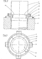
- the shear cylinder 5 has a circumferential recess 8 in its surface, which partially projects into the bore 4 of the crosshead 2 when the cylinder 5 is tensioned or fixed.
- a (first), e.g. half, divided ring 9 is used, which is supported on the lower shoulder 10 of the recess 8 or on the adjoining collar 11 of the cylinder 5 below.
- the split ring 9 has a turned collar 12 upwards, which has practically the same outer diameter as the bore 4 and therefore at the same time serves to radially fix the split ring 9 and to center the cylinder 5.
- a threaded ring 13 screwed onto the circumference of the cylinder 5 is used above the crosshead 2 to receive the from above downward forces, in particular the weight of the cylinder 5 with knife carriage 7.
- the threaded ring 13 lies flat, preferably with a flat end face 14, in the area around the bore 4 of the crosshead 2 on the latter. Because of the smooth contact surface, wedging or jamming cannot occur at this point. If a special centering is required here, the cylinder circumference can be provided with a corresponding fit 15. Instead, the threaded ring 13 can also have a centering projection projecting into the bore 4.
- the cylinder 5, aligned with the longitudinal axis 16 of the bore 4 is inserted vertically into the bore from above until the recess 8 protrudes from the bore on the underside of the crosshead 2.
- the (first) split ring 9 is inserted from the sides into the recess 8 and the cylinder 5 is raised slightly so that the collar 12 screwed onto the split ring 9 enters the bore 4 and the split ring with its upper shoulder 17th rests on the underside of the crosshead 2.
- the ring 9 is then fixed in the axial and radial directions.
- the threaded ring 13 on the top of the crosshead 2 is tightened to such an extent that the collar 12 of the divided ring 9 remains at least partially in the bore 4.
- Dismantling the cylinder 5 When dismantling the cylinder 5, the procedure is essentially the reverse of that for assembly. Dismantling begins with the cylinder being pushed upwards with the utmost force, as in the case of shearing, so that the threaded ring 13 can be released. Then the cylinder 5 is lowered so far that the individual parts of the split ring 9 are to be removed from the recess 8. Finally, the cylinder 5 - after uncoupling the knife carriage 7 - is completely pulled out of the bore 4 in the vertical direction 16.
- the cylinder 5 on the upper side of the crosshead 2 opposite the knife carriage 7 can not only by the threaded ring 13 but also by other locking means, e.g. with the aid of a second split ring 20 to be inserted into a second recess 19 according to FIGS. 2 and 3 under pretension.
- the second divided ring 20 is expediently held together with the aid of a one-piece banding ring 21.
- the second split ring 20 is in turn mounted under prestressing pressure with the aid of radially driven wedges 22 which, in order to prevent loosening or loosening, can be fixed, for example, with a weld seam 23.
- Fig. 3 shows a plan view of the head of the cylinder 5 in the event that four wedges 22 serve to receive the bias of the cylinder. 3 also shows the mutual association of the split ring 20 and bandage ring 21 and the parting joint 24 of the split ring.
Landscapes
- Engineering & Computer Science (AREA)
- Mechanical Engineering (AREA)
- Accessories And Tools For Shearing Machines (AREA)
- Shearing Machines (AREA)
- Working Measures On Existing Buildindgs (AREA)
- Formation And Processing Of Food Products (AREA)
Priority Applications (1)
| Application Number | Priority Date | Filing Date | Title |
|---|---|---|---|
| AT84101319T ATE20441T1 (de) | 1983-03-25 | 1984-02-09 | Schere fuer material beliebiger art. |
Applications Claiming Priority (2)
| Application Number | Priority Date | Filing Date | Title |
|---|---|---|---|
| DE3310894A DE3310894C1 (de) | 1983-03-25 | 1983-03-25 | Schere fuer Material beliebiger Art |
| DE3310894 | 1983-03-25 |
Publications (2)
| Publication Number | Publication Date |
|---|---|
| EP0120246A1 true EP0120246A1 (fr) | 1984-10-03 |
| EP0120246B1 EP0120246B1 (fr) | 1986-06-18 |
Family
ID=6194634
Family Applications (1)
| Application Number | Title | Priority Date | Filing Date |
|---|---|---|---|
| EP19840101319 Expired EP0120246B1 (fr) | 1983-03-25 | 1984-02-09 | Machine à cisailler |
Country Status (5)
| Country | Link |
|---|---|
| US (1) | US4574674A (fr) |
| EP (1) | EP0120246B1 (fr) |
| JP (1) | JPS59175918A (fr) |
| AT (1) | ATE20441T1 (fr) |
| DE (2) | DE3310894C1 (fr) |
Cited By (1)
| Publication number | Priority date | Publication date | Assignee | Title |
|---|---|---|---|---|
| WO2003098936A2 (fr) | 2002-05-22 | 2003-11-27 | Koninklijke Philips Electronics N.V. | Procede d'extraction d'un filigrane |
Citations (2)
| Publication number | Priority date | Publication date | Assignee | Title |
|---|---|---|---|---|
| AT290996B (de) * | 1967-10-03 | 1971-06-25 | Giovanni Busi | Schrott-Paketierpresse |
| DE2245049A1 (de) * | 1972-09-14 | 1974-03-21 | Siempelkamp Gmbh & Co | Hydraulische presse |
Family Cites Families (4)
| Publication number | Priority date | Publication date | Assignee | Title |
|---|---|---|---|---|
| DE18523C (de) * | C. W. MORITZ in Neustadt a. Rübenberge | Neuerungen an Ventilatoren | ||
| US765139A (en) * | 1903-09-22 | 1904-07-12 | Oscar Lohman | Reinforcer for bolts. |
| US3279297A (en) * | 1964-12-07 | 1966-10-18 | Logemann Brothers Co | Coupling means |
| JPS5334629U (fr) * | 1976-08-31 | 1978-03-27 |
-
1983
- 1983-03-25 DE DE3310894A patent/DE3310894C1/de not_active Expired
-
1984
- 1984-02-09 AT AT84101319T patent/ATE20441T1/de not_active IP Right Cessation
- 1984-02-09 EP EP19840101319 patent/EP0120246B1/fr not_active Expired
- 1984-02-09 DE DE8484101319T patent/DE3460232D1/de not_active Expired
- 1984-03-21 JP JP59052470A patent/JPS59175918A/ja active Pending
- 1984-03-23 US US06/592,864 patent/US4574674A/en not_active Expired - Fee Related
Patent Citations (2)
| Publication number | Priority date | Publication date | Assignee | Title |
|---|---|---|---|---|
| AT290996B (de) * | 1967-10-03 | 1971-06-25 | Giovanni Busi | Schrott-Paketierpresse |
| DE2245049A1 (de) * | 1972-09-14 | 1974-03-21 | Siempelkamp Gmbh & Co | Hydraulische presse |
Cited By (1)
| Publication number | Priority date | Publication date | Assignee | Title |
|---|---|---|---|---|
| WO2003098936A2 (fr) | 2002-05-22 | 2003-11-27 | Koninklijke Philips Electronics N.V. | Procede d'extraction d'un filigrane |
Also Published As
| Publication number | Publication date |
|---|---|
| DE3310894C1 (de) | 1984-09-06 |
| DE3460232D1 (en) | 1986-07-24 |
| EP0120246B1 (fr) | 1986-06-18 |
| ATE20441T1 (de) | 1986-07-15 |
| JPS59175918A (ja) | 1984-10-05 |
| US4574674A (en) | 1986-03-11 |
Similar Documents
| Publication | Publication Date | Title |
|---|---|---|
| DE3510926C2 (de) | Spannvorrichtung zum mechanischen Spannen von Befestigungselementen | |
| DE2837547C2 (de) | Zugkräfte zwischen zwei Bauteilen aufnehmendes, höhenverstellbares und Kippbewegungen zulassendes Lager | |
| EP0722809B1 (fr) | Dispositif d'accouplement | |
| DE2302732A1 (de) | Einstellbare daempfungsvorrichtung | |
| EP0817936B1 (fr) | Procede et dispositif de traction d'un tuyau pose ou a poser dans le sol | |
| DE3345959C2 (de) | Zylinderkopfbefestigungskonstruktion | |
| EP2847390A1 (fr) | Système d'ancrage dans une fondation pour machines industrielles | |
| EP3129147B1 (fr) | Dispositif de fixation de la tete d'un concasseur giratoire | |
| EP4299501B1 (fr) | Dispositif de liaison pour relier des segments de flèche d'une flèche d'une grue à tour | |
| EP2719504A1 (fr) | Dispositif de serrage pour l'étirement d'un boulon fileté | |
| EP0707549B1 (fr) | Dispositif pour la tension et la suspension de la roue directrice de vehicules chenilles | |
| AT519652A4 (de) | Dichtungsvorrichtung und Hydraulikkolben mit Dichtungsvorrichtung | |
| EP2882557B1 (fr) | Dispositif de sectionnement de câbles de haubanage | |
| DE2841952A1 (de) | Presse wie schmiedepresse o.dgl. | |
| EP0120246B1 (fr) | Machine à cisailler | |
| EP2789747A1 (fr) | Machine de compaction d'un sol | |
| DE19826924A1 (de) | Auslegerfixierung mit Einstellzylinder | |
| DE3035740C2 (fr) | ||
| DE2725033A1 (de) | Vorrichtung zur lagerung einer radialen stosskraeften ausgesetzten welle | |
| EP2604361B1 (fr) | Dispositif de coin de serrage pour la fixation d'outils sur des machines-outils | |
| DE1201289B (de) | Gebirgsanker | |
| DE10330523A1 (de) | Vorrichtung zum Abstützen eines Statorwickelkopfs | |
| DE20018186U1 (de) | Welle und Vorrichtung mit Welle zum Zerkleinern von Müll | |
| DE102022109427B4 (de) | Radialpresse | |
| EP4359206B1 (fr) | Presse radiale |
Legal Events
| Date | Code | Title | Description |
|---|---|---|---|
| PUAI | Public reference made under article 153(3) epc to a published international application that has entered the european phase |
Free format text: ORIGINAL CODE: 0009012 |
|
| AK | Designated contracting states |
Designated state(s): AT BE CH DE FR GB IT LI LU NL SE |
|
| 17P | Request for examination filed |
Effective date: 19840801 |
|
| GRAA | (expected) grant |
Free format text: ORIGINAL CODE: 0009210 |
|
| ITF | It: translation for a ep patent filed | ||
| AK | Designated contracting states |
Kind code of ref document: B1 Designated state(s): AT BE CH DE FR GB IT LI LU NL SE |
|
| REF | Corresponds to: |
Ref document number: 20441 Country of ref document: AT Date of ref document: 19860715 Kind code of ref document: T |
|
| REF | Corresponds to: |
Ref document number: 3460232 Country of ref document: DE Date of ref document: 19860724 |
|
| ET | Fr: translation filed | ||
| PLBE | No opposition filed within time limit |
Free format text: ORIGINAL CODE: 0009261 |
|
| STAA | Information on the status of an ep patent application or granted ep patent |
Free format text: STATUS: NO OPPOSITION FILED WITHIN TIME LIMIT |
|
| 26N | No opposition filed | ||
| ITTA | It: last paid annual fee | ||
| EPTA | Lu: last paid annual fee | ||
| EAL | Se: european patent in force in sweden |
Ref document number: 84101319.6 |
|
| PGFP | Annual fee paid to national office [announced via postgrant information from national office to epo] |
Ref country code: SE Payment date: 19961206 Year of fee payment: 14 |
|
| PGFP | Annual fee paid to national office [announced via postgrant information from national office to epo] |
Ref country code: LU Payment date: 19970101 Year of fee payment: 14 |
|
| PGFP | Annual fee paid to national office [announced via postgrant information from national office to epo] |
Ref country code: FR Payment date: 19970121 Year of fee payment: 14 |
|
| PGFP | Annual fee paid to national office [announced via postgrant information from national office to epo] |
Ref country code: AT Payment date: 19970128 Year of fee payment: 14 |
|
| PGFP | Annual fee paid to national office [announced via postgrant information from national office to epo] |
Ref country code: NL Payment date: 19970130 Year of fee payment: 14 |
|
| PGFP | Annual fee paid to national office [announced via postgrant information from national office to epo] |
Ref country code: CH Payment date: 19970131 Year of fee payment: 14 |
|
| PGFP | Annual fee paid to national office [announced via postgrant information from national office to epo] |
Ref country code: GB Payment date: 19971230 Year of fee payment: 15 |
|
| PGFP | Annual fee paid to national office [announced via postgrant information from national office to epo] |
Ref country code: BE Payment date: 19980116 Year of fee payment: 15 |
|
| PG25 | Lapsed in a contracting state [announced via postgrant information from national office to epo] |
Ref country code: LU Free format text: LAPSE BECAUSE OF NON-PAYMENT OF DUE FEES Effective date: 19980209 Ref country code: AT Free format text: LAPSE BECAUSE OF NON-PAYMENT OF DUE FEES Effective date: 19980209 |
|
| PG25 | Lapsed in a contracting state [announced via postgrant information from national office to epo] |
Ref country code: SE Free format text: LAPSE BECAUSE OF NON-PAYMENT OF DUE FEES Effective date: 19980210 |
|
| PG25 | Lapsed in a contracting state [announced via postgrant information from national office to epo] |
Ref country code: LI Free format text: LAPSE BECAUSE OF NON-PAYMENT OF DUE FEES Effective date: 19980228 Ref country code: FR Free format text: THE PATENT HAS BEEN ANNULLED BY A DECISION OF A NATIONAL AUTHORITY Effective date: 19980228 Ref country code: CH Free format text: LAPSE BECAUSE OF NON-PAYMENT OF DUE FEES Effective date: 19980228 |
|
| REG | Reference to a national code |
Ref country code: GB Ref legal event code: 732E |
|
| PG25 | Lapsed in a contracting state [announced via postgrant information from national office to epo] |
Ref country code: NL Free format text: LAPSE BECAUSE OF NON-PAYMENT OF DUE FEES Effective date: 19980901 |
|
| REG | Reference to a national code |
Ref country code: CH Ref legal event code: PL |
|
| EUG | Se: european patent has lapsed |
Ref document number: 84101319.6 |
|
| NLV4 | Nl: lapsed or anulled due to non-payment of the annual fee |
Effective date: 19980901 |
|
| REG | Reference to a national code |
Ref country code: FR Ref legal event code: ST |
|
| PG25 | Lapsed in a contracting state [announced via postgrant information from national office to epo] |
Ref country code: GB Free format text: LAPSE BECAUSE OF NON-PAYMENT OF DUE FEES Effective date: 19990209 |
|
| PG25 | Lapsed in a contracting state [announced via postgrant information from national office to epo] |
Ref country code: BE Free format text: LAPSE BECAUSE OF NON-PAYMENT OF DUE FEES Effective date: 19990228 |
|
| BERE | Be: lapsed |
Owner name: LINDEMANN MASCHINENFABRIK G.M.B.H. Effective date: 19990228 |
|
| GBPC | Gb: european patent ceased through non-payment of renewal fee |
Effective date: 19990209 |
|
| PGFP | Annual fee paid to national office [announced via postgrant information from national office to epo] |
Ref country code: DE Payment date: 20010115 Year of fee payment: 18 |
|
| PG25 | Lapsed in a contracting state [announced via postgrant information from national office to epo] |
Ref country code: DE Free format text: LAPSE BECAUSE OF NON-PAYMENT OF DUE FEES Effective date: 20020903 |