US4574674A - Shearing machine for cutting up miscellaneous material - Google Patents
Shearing machine for cutting up miscellaneous material Download PDFInfo
- Publication number
- US4574674A US4574674A US06/592,864 US59286484A US4574674A US 4574674 A US4574674 A US 4574674A US 59286484 A US59286484 A US 59286484A US 4574674 A US4574674 A US 4574674A
- Authority
- US
- United States
- Prior art keywords
- crosshead
- cylinder
- opening
- ring
- piston assembly
- Prior art date
- Legal status (The legal status is an assumption and is not a legal conclusion. Google has not performed a legal analysis and makes no representation as to the accuracy of the status listed.)
- Expired - Fee Related
Links
- 238000010008 shearing Methods 0.000 title claims abstract description 42
- 239000000463 material Substances 0.000 title claims abstract description 8
- 239000002699 waste material Substances 0.000 claims description 3
- -1 for example Substances 0.000 claims description 2
- 239000002184 metal Substances 0.000 claims description 2
- 238000003466 welding Methods 0.000 claims description 2
- 238000009434 installation Methods 0.000 description 8
- 238000010276 construction Methods 0.000 description 5
- 238000011068 loading method Methods 0.000 description 3
- 230000008439 repair process Effects 0.000 description 2
- 239000003923 scrap metal Substances 0.000 description 2
- 230000004323 axial length Effects 0.000 description 1
- 230000007423 decrease Effects 0.000 description 1
- 230000000694 effects Effects 0.000 description 1
- 239000012530 fluid Substances 0.000 description 1
- 238000003754 machining Methods 0.000 description 1
- 238000000034 method Methods 0.000 description 1
- 230000004048 modification Effects 0.000 description 1
- 238000012986 modification Methods 0.000 description 1
- 230000000284 resting effect Effects 0.000 description 1
Images


Classifications
-
- B—PERFORMING OPERATIONS; TRANSPORTING
- B23—MACHINE TOOLS; METAL-WORKING NOT OTHERWISE PROVIDED FOR
- B23D—PLANING; SLOTTING; SHEARING; BROACHING; SAWING; FILING; SCRAPING; LIKE OPERATIONS FOR WORKING METAL BY REMOVING MATERIAL, NOT OTHERWISE PROVIDED FOR
- B23D35/00—Tools for shearing machines or shearing devices; Holders or chucks for shearing tools
-
- B—PERFORMING OPERATIONS; TRANSPORTING
- B23—MACHINE TOOLS; METAL-WORKING NOT OTHERWISE PROVIDED FOR
- B23D—PLANING; SLOTTING; SHEARING; BROACHING; SAWING; FILING; SCRAPING; LIKE OPERATIONS FOR WORKING METAL BY REMOVING MATERIAL, NOT OTHERWISE PROVIDED FOR
- B23D15/00—Shearing machines or shearing devices cutting by blades which move parallel to themselves
-
- F—MECHANICAL ENGINEERING; LIGHTING; HEATING; WEAPONS; BLASTING
- F16—ENGINEERING ELEMENTS AND UNITS; GENERAL MEASURES FOR PRODUCING AND MAINTAINING EFFECTIVE FUNCTIONING OF MACHINES OR INSTALLATIONS; THERMAL INSULATION IN GENERAL
- F16B—DEVICES FOR FASTENING OR SECURING CONSTRUCTIONAL ELEMENTS OR MACHINE PARTS TOGETHER, e.g. NAILS, BOLTS, CIRCLIPS, CLAMPS, CLIPS OR WEDGES; JOINTS OR JOINTING
- F16B2200/00—Constructional details of connections not covered for in other groups of this subclass
- F16B2200/40—Clamping arrangements where clamping parts are received in recesses of elements to be connected
- F16B2200/406—Clamping parts being collars, bushings or wedges
-
- Y—GENERAL TAGGING OF NEW TECHNOLOGICAL DEVELOPMENTS; GENERAL TAGGING OF CROSS-SECTIONAL TECHNOLOGIES SPANNING OVER SEVERAL SECTIONS OF THE IPC; TECHNICAL SUBJECTS COVERED BY FORMER USPC CROSS-REFERENCE ART COLLECTIONS [XRACs] AND DIGESTS
- Y10—TECHNICAL SUBJECTS COVERED BY FORMER USPC
- Y10T—TECHNICAL SUBJECTS COVERED BY FORMER US CLASSIFICATION
- Y10T83/00—Cutting
- Y10T83/929—Tool or tool with support
- Y10T83/9457—Joint or connection
- Y10T83/9473—For rectilinearly reciprocating tool
Definitions
- This invention relates to a shearing machine for cutting up miscellaneous material, for example scrap metal, waste, refuse, bars, strands or cordage.
- the machine includes a shearing blade carrier which is slidably guided in a closed frame. It may also include a holding-down device.
- the blade carrier and the holding down device when provided, each have a drive comprising a cylinder-piston assembly fixed in an opening through a crosshead.
- two drive cylinders are usually housed alongside one another.
- One cylinder is connected via its piston with a main shearing blade carrier and the other constitutes the drive of a so-called holding-down device, which holds down and fixes the material to be cut during the shearing operation.
- the cylinder associated with the holding-down device is, on account of the smaller force which it has to produce, substantially smaller than the other cylinder designated as the shearing cylinder.
- the cylinders do not differ in principle from each other. The following description therefore applies equally to the shearing cylinder and the holding-down cylinder, even though only the shearing cylinder is described.
- the cylinders fixed in the crosshead are subjected to two forces oriented in their axial direction. Normally, only the weight of the drive units and accessories acts on the cylinders. This is accepted by a shoulder extending around the cylinder resting on the edge of the opening in the crosshead.
- a screw threaded ring is used which, after the cylinder has been inserted into the crosshead opening, is pushed onto the cylinder from below and is screwed onto a thread on the cylinder. The considerable shearing forces are therefore transmitted from the cylinder via the screwthread and the screwthread ring to the crosshead.
- this ring is held under prestress by a stressing system.
- the object of the present invention is to provide a less sensitive fixing for the drive cylinder or cylinders of a machine as initially described and to facilitate the installation and removal of the shearing cylinder and/or the holding down cylinder of a shearing machine suitable for material of any type, especially metal scrap, in conjunction with at least equivalent operational reliability and durability.
- a shearing machine for cutting up miscellaneous material for example, scrap metal, waste, refuse, bars, cordage or the like, comprising a shearing blade carrier which is slidably guided in a closed frame and a drive for reciprocating the blade carrier, the drive comprising a cylinder-piston assembly fixed in an opening through a crosshead of the frame
- the cylinder is supported to counteract reaction forces from the blade carrier towards the crosshead, against the side of the crosshead which faces towards the blade carrier by a divided ring, which engages in a circumferential recess in the outside of the cylinder and also at least partly in the opening in the side of the crosshead facing towards the blade carrier and means is provided to fix the cylinder on the side of the crosshead remote from the blade carrier, this means bearing with a prestress against the side of the crosshead remote from the blade carrier.
- the end fixing means of the cylinder accepting the prestress is relieved from the high forces acting during operation of the shearing machine and moreover the fixing means are situated at a position much more readily accessible for installation and dismantling than in the shearing machines at present in use.
- the invention offers especial advantages, since installation can now be carried out substantially without overhead work.
- the cylinder is supported, at the side of the crosshead remote from the blade carrier, by means of a screwthreaded ring screwed onto the circumference of the cylinder or of a second divided ring, which engages in a further circumferential recess in the outside of the cylinder.
- the invention consists in principle in providing, in place of the screw thread which hitherto received the screwthreaded ring, an annular recess or groove in the external surface of the cylinder and in replacing the screwthreaded ring having a centering projection, by an unthreaded, divided, preferably bisected, ring, which is fitted into the recess and, for accepting the reaction forces during shearing, projects with its end face which is towards the crosshead sufficiently far radially outwards beyond the edge of the opening which holds the shearing cylinder and bears, with its end face which faces towards the blade carrier, against the shoulder forming the boundary of the recess in the cylinder or against the thus formed flange at the end of the cylinder.
- the recess must therefore be cut sufficiently deep for the flange of the cylinder which adjoins it to be capable of receiving the entire reaction from the shearing blade.
- the recess is so formed in the cylinder surface that it extends at least partly into the opening in the crosshead when the cylinder is fixed in position.
- a circumferential recess or seating may likewise be provided, which seats the parts of the divided ring projecting radially beyond the cylinder surface, so that the crosshead opening is of stepped construction.
- the divided ring can also be recessed entirely in the crosshead in the prestressed position of the cylinder.
- the divided ring has at least one centering projection projecting into the opening, the maximum diameter of which projection is equal to the diameter of the cylinder. It is then sufficient so to dimension the recess in the cylinder surface that the centering projection extends into the crosshead opening when the cylinder is prestressed.
- a screwthreaded ring screwed on to a thread on the cylinder circumference on the side of the crosshead remote from the blade carrier is preferably used.
- This threaded ring can bear with its end face flatly upon the crosshead in the region of the circumference of the opening which holds the cylinder. Since the threaded ring on this side of the crosshead need accept only considerably smaller forces than the threaded ring which was previously provided on the side of the crosshead adjacent the blade carrier, it can be of correspondingly more slender construction.
- Centering of the cylinder in the region of this threaded ring is achieved by a fit at the circumference of the cylinder corresponding to the diameter of the opening. Instead of such a fit at the cylinder circumference, however, a centering projection of the screwthreaded ring extending into the bore of the crosshead may be provided.
- the end fixing of the cylinder which generates the prestress on the side of the crosshead remote from the blade carrier may be formed by the aforementioned, second divided ring.
- This second divided ring can likewise extend into a circumferential recess in the outside of the cylinder.
- the second divided ring is held together by means of a single-piece banding ring.
- the installation of the second divided ring is preferably carried out with prestressing pressure produced by means of wedges driven radially inwards. Each wedge is advantageously fixed by means of a weld, in order to prevent releasing or loosening. Since the connection in accordance with this invention cannot become loose if installation is properly carried out, a restressing facility is not necessary and the welding of the wedges does not constitute any disadvantage.
- the relevant cylinder is inserted from above into the opening provided in the crosshead.
- the abutment formed, for example, as a threaded ring on the upper face of the crosshead is screw upwards sufficiently far from its final position for the divided ring on the lower side of the crosshead to be introduced without difficulty into the recess in the cylinder provided for this purpose.
- the cylinder is then first slightly raised, for example by means of a crane used for installation, so that the threaded ring on the upper side of the crosshead can be temporarily tightened.
- the divided ring partly enters the opening in the crosshead or a circumferential recess provided at the end of the opening when the threaded ring is thus lightly tightened up, so that the divided ring is fixed in the radial direction.
- the divided ring In the axial direction the divided ring cannot be moved, because in its axial length it is exactly adapted to the dimensions of the recess.
- the cylinder For the final tightening or prestressing of the threaded ring provided on the upper face of the crosshead, the cylinder is connected to its pressure lines and is pressurized with fluid, so that the blade carrier of the machine which is coupled to the cylinder piston is extended as far as a stop. The blade carrier is then pressed with maximum force against the stop, so that the divided ring is forced upwards and the threaded ring on the upper face of the crosshead can be tightened without great expenditure of force with the prestress required for operation.
- Dismantling is carried out in the reverse sequence to assembly.
- the blade carrier is first pressed with the maximum possible force against the abutment, so that the prestress acting upon the threaded ring is considerably reduced and complete releasing of the threaded ring is possible without great difficulty.
- the cylinder can be pulled out upwards from the opening in the crosshead.
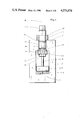
- FIG. 1 is a vertical section through one example
- FIG. 2 is a vertical section showing a modification of the example of FIG. 1;
- FIG. 3 is a plan view of the cylinder mounting shown in FIG. 2;
- FIG. 4 is a vertical section through another example of the present invention.
- FIG. 5 is a vertical section similar to FIGS. 1 and 4 but viewed in a plane at right angles to the plane viewed in FIGS. 1 and 4 and illustrating a holding down device.
- a machine shown in FIG. 1 comprises a frame 1, having a crosshead 2 and a fixed, counterknife 3 disposed in the lower part of the frame.
- a shearing cylinder 5 is fixed in an opening 4 in the crosshead 2.
- Its associated piston 6 drives a blade carrier 7, as seen in the direction of FIG. 1; behind or in front of the shearing cylinder 5, there is also a cylinder together with piston for driving a holding-down device.
- the holding-down cylinder is also fixed in a bore in the crosshead 2.
- the holding-down cylinder and piston, which are not shown, are except for their dimensions constructed the same as the shearing cylinder and piston. The same applies also for the fixing described below of the cylinder, which is explained with reference to the fixing of the shearing cylinder.
- the shearing cylinder 5 has in its outside surface a circumferential recess 8 which, when the cylinder 5 is stressed and fixed, projects partly into the opening 4 in the crosshead 2.
- a divided ring 9 for example a bisected ring, which rests against a lower shoulder 10 of the recess 8, that is on a flange 11 of the cylinder 5 adjoining the recess 8.
- the divided ring 9 has, towards its top, a projection or stub 12 formed by machining, which has virtually the same external diameter as the diameter of the opening 4 and therefore serves both for radially fixing the divided ring 9 and for centering the cylinder 5.
- a screwthreaded ring 13 which is screwed on to the circumference of the cylinder 5 above the crosshead 2, serves for withstanding the downwardly oriented forces, that is in particular the weight of the cylinder 5 and the blade carrier 7.
- the screwthreaded ring 13 lies flatly, preferably with a flat end face 14, against the region around the opening 4 in the crosshead 2. On account of the flat seating surface, jamming or wedging cannot take place at this position. If an accurate centering is necessary here, the cylinder circumference can be furnished with an appropriate collar 15 which fits exactly in the opening 4. Instead of this, the threaded ring 13 may also possess a centering projection or stub extending in to the opening 4.
- the cylinder 5, which is aligned with the longitudinal axis 16 of the opening 4 is introduced vertically from above into the opening until the recess 8 projects entirely out of the opening on the lower side of the crosshead 2.
- the divided ring 9 is inserted from the sides into the recess 8 and the cylinder 5 is slightly raised, so that the projection or stub 12 on the divided ring 9 enters the bore 4 and the divided ring bears with its upper shoulder 17 against the lower face of the crosshead 2.
- the ring 9 is thus fixed in the axial and radial directions.
- the screwthreaded ring 13 on the upper face of the crosshead 2 is then tightened up sufficiently for the stub 12 of the divided ring 9 to remain at least partly in the bore 4.
- the pressure pipes are then fitted to the cylinder 5 and the cylinder is pressurised so that the blade carrier is pushed downwards against an abutment 18 and exerts a corresponding reaction force on the cylinder 5 and thus, via the divided ring 9, on the crosshead 2. Under this prestress, the screwthreaded ring 13 is then further tightened, so that the cylinder 5 is fixed under prestress in the desired position.
- Dismantling of the cylinder 5 basically the reverse sequence is used to that for installation. Dismantling starts with the cylinder being pressed upwards by loading as in shearing with an extremely high force, so that the screwthreaded ring 13 may be loosened. Thereupon the cylinder 5 is lowered sufficiently far for the separate parts of the divided ring 9 to be removed from the recess 8. Finally, the cylinder 5, after the knife slide 7 has been uncoupled, is pulled out in a vertical direction 16 completely out of the bore 4.
- the cylinder 5 may also be fixed under prestress against the upper face of the crosshead 2 remote from the blade carrier 7, not by the threaded ring 13, but, instead of this, by other fixing means, such as by means of a second divided ring 20 as shown in FIGS. 2 and 3, inserted into a second recess 19 in the outside of the cylinder.
- the second divided ring 20 is advantageously held together by means of a single-piece banding ring 21. The installation of the second divided ring 20 once again takes place under prestressing pressure by means of wedges 22 driven radially inwards.
- each wedge 22 may be fixed, for example, with a weld 23. If the prestress is produced with a maximum cylinder force, higher operating forces, which could release this connection even if correctly installed, can never occur, so that a restressing facility is not necessary.
- FIG. 3 is a plan view of the head of the cylinder 5 for the case in which four wedges 22 serve for accepting the prestress of the cylinder.
- FIG. 3 also shows the mutual relationship of the divided ring 20 and the banding ring 21 and the separating joints 24 of the divided ring.
- FIG. 4 another example of the invention is illustrated, similar to FIG. 1, however, a shoulder 17 is formed in the opening 4 with a corresponding shoulder formed on the stepped circumferential surface of the device ring 9 bearing against it. As distinguished from the example in FIG. 1, in FIG. 4 the divided ring 9 is completely recessed within the opening 4.
- FIG. 5 a holding down cylinder 5' is shown spaced laterally from the shearing cylinder 5 for holding the material while it is being sheared.
- the holding down cylinder 5' is similar to the shearing cylinder 5 and its individual parts are identified with the same reference numerals with the addition of a prime (').
Landscapes
- Engineering & Computer Science (AREA)
- Mechanical Engineering (AREA)
- Accessories And Tools For Shearing Machines (AREA)
- Shearing Machines (AREA)
- Working Measures On Existing Buildindgs (AREA)
- Formation And Processing Of Food Products (AREA)
Applications Claiming Priority (2)
| Application Number | Priority Date | Filing Date | Title |
|---|---|---|---|
| DE3310894A DE3310894C1 (de) | 1983-03-25 | 1983-03-25 | Schere fuer Material beliebiger Art |
| DE3310894 | 1983-03-25 |
Publications (1)
| Publication Number | Publication Date |
|---|---|
| US4574674A true US4574674A (en) | 1986-03-11 |
Family
ID=6194634
Family Applications (1)
| Application Number | Title | Priority Date | Filing Date |
|---|---|---|---|
| US06/592,864 Expired - Fee Related US4574674A (en) | 1983-03-25 | 1984-03-23 | Shearing machine for cutting up miscellaneous material |
Country Status (5)
| Country | Link |
|---|---|
| US (1) | US4574674A (fr) |
| EP (1) | EP0120246B1 (fr) |
| JP (1) | JPS59175918A (fr) |
| AT (1) | ATE20441T1 (fr) |
| DE (2) | DE3310894C1 (fr) |
Families Citing this family (1)
| Publication number | Priority date | Publication date | Assignee | Title |
|---|---|---|---|---|
| WO2003098936A2 (fr) | 2002-05-22 | 2003-11-27 | Koninklijke Philips Electronics N.V. | Procede d'extraction d'un filigrane |
Citations (3)
| Publication number | Priority date | Publication date | Assignee | Title |
|---|---|---|---|---|
| DE18523C (de) * | C. W. MORITZ in Neustadt a. Rübenberge | Neuerungen an Ventilatoren | ||
| US765139A (en) * | 1903-09-22 | 1904-07-12 | Oscar Lohman | Reinforcer for bolts. |
| US3279297A (en) * | 1964-12-07 | 1966-10-18 | Logemann Brothers Co | Coupling means |
Family Cites Families (3)
| Publication number | Priority date | Publication date | Assignee | Title |
|---|---|---|---|---|
| FR1581905A (fr) * | 1967-10-03 | 1969-09-19 | ||
| DE2245049A1 (de) * | 1972-09-14 | 1974-03-21 | Siempelkamp Gmbh & Co | Hydraulische presse |
| JPS5334629U (fr) * | 1976-08-31 | 1978-03-27 |
-
1983
- 1983-03-25 DE DE3310894A patent/DE3310894C1/de not_active Expired
-
1984
- 1984-02-09 AT AT84101319T patent/ATE20441T1/de not_active IP Right Cessation
- 1984-02-09 EP EP19840101319 patent/EP0120246B1/fr not_active Expired
- 1984-02-09 DE DE8484101319T patent/DE3460232D1/de not_active Expired
- 1984-03-21 JP JP59052470A patent/JPS59175918A/ja active Pending
- 1984-03-23 US US06/592,864 patent/US4574674A/en not_active Expired - Fee Related
Patent Citations (3)
| Publication number | Priority date | Publication date | Assignee | Title |
|---|---|---|---|---|
| DE18523C (de) * | C. W. MORITZ in Neustadt a. Rübenberge | Neuerungen an Ventilatoren | ||
| US765139A (en) * | 1903-09-22 | 1904-07-12 | Oscar Lohman | Reinforcer for bolts. |
| US3279297A (en) * | 1964-12-07 | 1966-10-18 | Logemann Brothers Co | Coupling means |
Also Published As
| Publication number | Publication date |
|---|---|
| DE3310894C1 (de) | 1984-09-06 |
| DE3460232D1 (en) | 1986-07-24 |
| EP0120246B1 (fr) | 1986-06-18 |
| ATE20441T1 (de) | 1986-07-15 |
| JPS59175918A (ja) | 1984-10-05 |
| EP0120246A1 (fr) | 1984-10-03 |
Similar Documents
| Publication | Publication Date | Title |
|---|---|---|
| US6216766B1 (en) | Fluid-tight coupling device for a feeder pipe | |
| AU629006B2 (en) | Quick-fastening nut | |
| WO2013090984A1 (fr) | Attache pour revêtement | |
| EP4340998B1 (fr) | Système et procédé de fixation de manteau pour un concasseur à cône | |
| US6345927B1 (en) | Weld reinforcement | |
| CN101487489B (zh) | 使用劈开的螺纹紧固件加预应力的装置 | |
| US5600689A (en) | Method and apparatus for repairing boiling water reactor shrouds utilizing tie-rods with multiple longitudinal members | |
| US6862789B1 (en) | Assembly tool | |
| US7210915B2 (en) | Powder compacting apparatus | |
| US4574674A (en) | Shearing machine for cutting up miscellaneous material | |
| US5163775A (en) | Anchor bolt repair coupling | |
| US20140109406A1 (en) | Jet pump diffuser stack repair | |
| US3337143A (en) | Rock crusher | |
| US5622105A (en) | High-pressure press | |
| US12359755B2 (en) | Pipe joint, spacer provided in pipe joint, and dividing piece constituting spacer | |
| US3099075A (en) | Power operated stud tensioner | |
| CN216421261U (zh) | 一种飞剪机剪刃锁紧装置 | |
| US4532955A (en) | Wedge lock valve retainer | |
| JP2005040864A (ja) | 圧縮プレス | |
| CN111354482B (zh) | 一种填料环可重复使用的堆芯仪表组件 | |
| EP3970164B1 (fr) | Dispositif de fixation d'enveloppe de coeur de réacteur nucléaire | |
| KR102128820B1 (ko) | 파일의 무용접 이음장치 | |
| US2918039A (en) | Hydraulically actuated pressure foot for wood grinders | |
| CN220006800U (zh) | 发动机缸体夹紧组件及具有该夹紧组件的夹具工装 | |
| JP3023693U (ja) | 油圧ブレーカ |
Legal Events
| Date | Code | Title | Description |
|---|---|---|---|
| AS | Assignment |
Owner name: LINDEMANN MASCHINENFABRIK GMBH ERKRATHER STRABE 40 Free format text: ASSIGNMENT OF ASSIGNORS INTEREST.;ASSIGNOR:MARX, HELMUT;REEL/FRAME:004244/0522 Effective date: 19840319 |
|
| FEPP | Fee payment procedure |
Free format text: PAYOR NUMBER ASSIGNED (ORIGINAL EVENT CODE: ASPN); ENTITY STATUS OF PATENT OWNER: LARGE ENTITY |
|
| FPAY | Fee payment |
Year of fee payment: 4 |
|
| FPAY | Fee payment |
Year of fee payment: 8 |
|
| REMI | Maintenance fee reminder mailed | ||
| LAPS | Lapse for failure to pay maintenance fees | ||
| FP | Lapsed due to failure to pay maintenance fee |
Effective date: 19980311 |
|
| STCH | Information on status: patent discontinuation |
Free format text: PATENT EXPIRED DUE TO NONPAYMENT OF MAINTENANCE FEES UNDER 37 CFR 1.362 |