EP0120320A2 - Rahmenwerk für Seriendrucker - Google Patents
Rahmenwerk für Seriendrucker Download PDFInfo
- Publication number
- EP0120320A2 EP0120320A2 EP84101993A EP84101993A EP0120320A2 EP 0120320 A2 EP0120320 A2 EP 0120320A2 EP 84101993 A EP84101993 A EP 84101993A EP 84101993 A EP84101993 A EP 84101993A EP 0120320 A2 EP0120320 A2 EP 0120320A2
- Authority
- EP
- European Patent Office
- Prior art keywords
- side plates
- rider
- screw
- side plate
- opening
- Prior art date
- Legal status (The legal status is an assumption and is not a legal conclusion. Google has not performed a legal analysis and makes no representation as to the accuracy of the status listed.)
- Granted
Links
Images

Classifications
-
- B—PERFORMING OPERATIONS; TRANSPORTING
- B41—PRINTING; LINING MACHINES; TYPEWRITERS; STAMPS
- B41J—TYPEWRITERS; SELECTIVE PRINTING MECHANISMS, i.e. MECHANISMS PRINTING OTHERWISE THAN FROM A FORME; CORRECTION OF TYPOGRAPHICAL ERRORS
- B41J29/00—Details of, or accessories for, typewriters or selective printing mechanisms not otherwise provided for
- B41J29/02—Framework
Definitions
- the present invention relates to a serial printer frame and, more pre cisely, to the means securing the platen and the printing carriage guiding bars to such frame.
- the frame of a serial printer is generally constituted by a basement and by two side plates provided with suitable housings where the ends of the platen and of the carriage guiding bars are inserted and steadi ly restrained.
- the printing carriage where a printing head is mounted, slides along the guiding bars to subsequently take different printing positions along a printing line.
- the carriage is moved by a motor, preferably a step motor, through a flexible transmission, generally and preferably a toothed belt.
- the paper feeding for the printing of several lines is performed by suitable feeding elements, such as tractors or pin wheels, or by a cy lindric shaped platen rotatable around its axis and which cooperates with suitable pressure rollers pressing the paper against the platen.
- suitable feeding elements such as tractors or pin wheels, or by a cy lindric shaped platen rotatable around its axis and which cooperates with suitable pressure rollers pressing the paper against the platen.
- a perfect parallelism between the printing platen and the printing car riage guiding bars is required in the serial printers and, particularly, in those printers which must perform high quality printing. In this way a constant distance between printing head and printing pla ten is assured along the whole printing line, so that a constant impact energy is obtained and the printed alphanumerical characters are perfectly matched as to an imaginary median line of the printing line.
- the lack of parallelism is generally due both to the defective position ing of the housings intended to receive the ends of the platen and of the guiding bars on the frame side plates, and to the possible slacks between the side plate housings and the ends of the platen or the guiding bars.
- These adjusting means consist of fixing and gauging screws which act in radial directions contained in the side plate plane or in a plane pa- rallely thereto.
- the housings in each side plate are obtained by a simple blanking operation and consist of V shaped housings providing a well definite refe rence and support dihedral.
- the possible position inaccuracy in the blanking of the side plates does not affect at all the relative position of the housings therein. Also the possible wear of the blanking fixture (die and punch) equally affects the relative distances of the housings on both side plates.
- the platen and guiding bar ends are firmly pressed in the related dihe drals by retaining riders which eliminate the slacks among the elements by performing a suitable pressure on said ends towards the dihedral apex.
- the clamping riders are fixed to the panels by tapered head screws which get through the riders and are screwed to the side plates perpendicularly to the plate plane.
- the riders pressure on the platen and guiding bars ends is obtained by interaction of the tapered screw heads with corresponding tapered housings.
- the distance between the contact point of the riders positioned for the assembling, with the platen or the bar ends and the axis of the screw housings in the side plates is greater than the distance between the contact point of the riders with the platen or the bar ends and the axis of the tapered housings in the riders.
- the riders are preferably embodied with plastic material in order to assure a suitable elastic extension.
- Figure 1 shows the elements of a serial printer frame essential for understanding the present invention.
- the frame of Fig. 1 comprises 2 side plates lA, 1B firmly restrained to a basement 1C.
- Both basement 1C and side plates lA, 1B are in metal sheet of suitable thickness in order to provide a high strength to the equipment.
- the two side plates 1A, 1B are plane and identical each other.
- Side plates lA, 1B of Fig. 1 support guiding bars 4, 5 and a shaft 2 on which a cylindrical platen 3 is mounted.
- a printing carriage not shown, axially slides along the guiding bars. It is mounted on guiding bar 4 by means of axial bushings or bearings. Guiding bar 5 generally acts as guiding rail to avoid the carriage rota tion around bar 4.
- the platen may be a fixed or a rotating platen.
- Fig. 1 shows the rotating platen case.
- shaft 2 The ends of shaft 2 are engaged in two bearings 6A, 6B which are housed in two housings 7A, 7B of side plates 1A, 1B respectively.
- Such ends may protrude externally from side plates 1A, 1B for coupling with motor means, not shown.
- the ends of guiding bar 4 are directly housed into two housings 8A, 8B of side plates 1A, 1B respectively.
- Such ends protrude externally from side plates 1A, 1B.
- the ends of guiding bars 5 are engaged in two holes 10A, 10B of side plates 1A, 1B through two housings 9A, 9B.
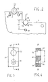
- Fig. 2 partially shows the contour of one of the side plates.
- V shaped housing 7 constitutes a supporting dihedral where bearing 6 lays in a stable position by contacting the housing in two generating lines 30, 31.
- housing 8 V shaped too, constitutes a supporting dihedral stable where the end of bar 4 lays in avposition by contacting the housing in two generating lines 33, 34.
- the distance between bearing 6 axis and bar 4 axis is equal on both the side plates and such distance is not affected by positioning slacks.
- bearings 6A, 6B are steady pressed in housings 7A, 7B by two riders 11A, 11B respectively.
- Such riders are constituted by a semitoroidal body 12A, 12B inside which bearings 6A, 6B are respec tively housed.
- the body externally protrudes with two fixing ears each one provided with a hole 15A, 15B and 16A, 16B respectively.
- the riders are fixed to side plates 1A, 1B respectively by means of tapered head screws 13A, 14A, 13B, 14B respectively.
- Such screws gets through holes 15A, 15B and 16A, 16B and are screwed into corresponding threaded housings formed on the side plates and respectively indicated by reference numbers 19A, 20A, 19B, 20B.
- the ends of guiding bar 4 are steady pressed in housings 8A 8B by two riders 21A, 21B respectively.
- Riders 21A, 21B are fixed to the side plates, each one by a tapered head screw 24A, 24B respectively, which is engaged in a second hole 23A, 23B respectively of the riders and is screwed in a corresponding threaded housing, 25A, 25B respectively, formed in the side plates.
- Screws 13, 14, 24 act with a screwing axis perpen dicular to the side plates plane (and therefore parallel to the axis of the platen and of the guiding bars) and, once clamped they steady press riders 11A, 11B, 21A, 21B against the side plates.
- threaded housing 25 is arranged in order that its axis has a distance H1 from generating line 38 of bar 4 more far away when this last is engaged into dihedral 8.
- Fig. 3 and 4 respectively show in front view and in section view accor ding to plane A-A, rider 21.
- the rider has an upper tapered opening 22 and a lower opening 23.
- Upper opening 22 is intended to receive the guiding bar end and has a diameter slightly larger than the bar to ease its insertion.
- Lower opening 23 is intended to receive a fixing screw and comprises a cylindrical portion 35 and a tapered housing 36.
- the axis of tapered housing 36, parallel to the axis of opening 22, is at a distance H from generating line 37 more far away of opening 22.
- H is suitably smaller than H1.
- Dl of seat 35 must be equal to D + (H1 - H) ⁇ 2.
- Such alignment may be established even if H is lesser than H1 owing to the opening diameter Dl which is wider than the screw and the threaded housing 25 diameter.
- Screw 24 is inserted into opening 23 and it is screwed into housing 25.
- Screw 24 when screwed into housing 25, has an eccentric position as to the opening 23 that is its axis is in opposition to generating line 37 as regards the axis of tapered housing 36.
- the tapered head begins to interfere with the lower surface of tapered housing 36 and pull downwords rider 21 in order to make tapered housing 36 coaxial to the screw.
- riders 11A, 11B The function carried out by riders 11A, 11B is the same even if, in this case, the clamping occurs by means of two screws, instead of one and the rider body acts on bearings 6A, 6B by elongating out of the external surface of the side plates towards the inside.
- side plates 1A and 1B may consists in plane metallic elements obtained by blanking and bending operations are not required for obtaining support or fixing wings for rider of conventional type, where clamping screws acts in the same direction of the force they have to perform.
- the described printed frame is only a preferred embodiment of the invention and that several variants can be brought. Riders such as the disclosed ones can for instance be used only for positioning the platen bearings; while the guiding bar ends may be po sitioned into the corrisponding housings by different devices. Likewise, considering the rider structure, the cylindric shaped housings 35 can have a form different from the one described which has circular section of diameter Dl suitably wider than the one of the screws they have to receive.
- they may consist of a groove with semicircular ends, having a widness equal to the diameter of the screw to be housed.
- Such grooves may be eccentrically elongated as to the tapered portion in order to allow at first the easy insertion, without interference, of the screw in eccentric position as to the tapered housing, and then the relative shift of the screw within the groove, without interference, up to the coaxial alignment of the screw and of the tapered housing.
Landscapes
- Accessory Devices And Overall Control Thereof (AREA)
- Character Spaces And Line Spaces In Printers (AREA)
- Common Mechanisms (AREA)
Applications Claiming Priority (2)
| Application Number | Priority Date | Filing Date | Title |
|---|---|---|---|
| IT20172/83A IT1160812B (it) | 1983-03-21 | 1983-03-21 | Struttura meccanica di una stampante seriale |
| IT2017283 | 1983-03-21 |
Publications (3)
| Publication Number | Publication Date |
|---|---|
| EP0120320A2 true EP0120320A2 (de) | 1984-10-03 |
| EP0120320A3 EP0120320A3 (en) | 1986-01-29 |
| EP0120320B1 EP0120320B1 (de) | 1988-05-11 |
Family
ID=11164397
Family Applications (1)
| Application Number | Title | Priority Date | Filing Date |
|---|---|---|---|
| EP84101993A Expired EP0120320B1 (de) | 1983-03-21 | 1984-02-25 | Rahmenwerk für Seriendrucker |
Country Status (5)
| Country | Link |
|---|---|
| EP (1) | EP0120320B1 (de) |
| KR (1) | KR880001141B1 (de) |
| DE (1) | DE3471046D1 (de) |
| FI (1) | FI77603C (de) |
| IT (1) | IT1160812B (de) |
Cited By (5)
| Publication number | Priority date | Publication date | Assignee | Title |
|---|---|---|---|---|
| FR2617432A1 (fr) * | 1987-07-01 | 1989-01-06 | Printronix Inc | Ensemble a navette interchangeable pour imprimante |
| EP0523569A1 (de) * | 1991-07-12 | 1993-01-20 | Canon Kabushiki Kaisha | Tintenstrahlaufzeichnungssystem |
| US5215395A (en) * | 1989-05-09 | 1993-06-01 | Texas Instruments Incorporated | Printer chassis |
| EP0814595A3 (de) * | 1996-06-21 | 1998-11-11 | Eastman Kodak Company | Gerät zum Erhalten der Positionsrelation eines Druckkopfes |
| US5896143A (en) * | 1992-09-03 | 1999-04-20 | Canon Kabushiki Kaisha | Ink jet recording apparatus |
Family Cites Families (2)
| Publication number | Priority date | Publication date | Assignee | Title |
|---|---|---|---|---|
| US2954951A (en) * | 1959-01-26 | 1960-10-04 | Viewlex Inc | Slide lock mounting means |
| US4222673A (en) * | 1978-09-20 | 1980-09-16 | Durango Systems, Inc. | Print head carriage assembly for serial printers |
-
1983
- 1983-03-21 IT IT20172/83A patent/IT1160812B/it active
-
1984
- 1984-02-25 EP EP84101993A patent/EP0120320B1/de not_active Expired
- 1984-02-25 DE DE8484101993T patent/DE3471046D1/de not_active Expired
- 1984-02-28 KR KR1019840000976A patent/KR880001141B1/ko not_active Expired
- 1984-03-16 FI FI841061A patent/FI77603C/fi not_active IP Right Cessation
Cited By (7)
| Publication number | Priority date | Publication date | Assignee | Title |
|---|---|---|---|---|
| FR2617432A1 (fr) * | 1987-07-01 | 1989-01-06 | Printronix Inc | Ensemble a navette interchangeable pour imprimante |
| US5215395A (en) * | 1989-05-09 | 1993-06-01 | Texas Instruments Incorporated | Printer chassis |
| EP0523569A1 (de) * | 1991-07-12 | 1993-01-20 | Canon Kabushiki Kaisha | Tintenstrahlaufzeichnungssystem |
| EP0570988A1 (de) * | 1991-07-12 | 1993-11-24 | Canon Kabushiki Kaisha | Tintenstrahlaufzeichnungssystem |
| US5480243A (en) * | 1991-07-12 | 1996-01-02 | Canon Kabushiki Kaisha | Ink jet recording system |
| US5896143A (en) * | 1992-09-03 | 1999-04-20 | Canon Kabushiki Kaisha | Ink jet recording apparatus |
| EP0814595A3 (de) * | 1996-06-21 | 1998-11-11 | Eastman Kodak Company | Gerät zum Erhalten der Positionsrelation eines Druckkopfes |
Also Published As
| Publication number | Publication date |
|---|---|
| FI77603B (fi) | 1988-12-30 |
| DE3471046D1 (en) | 1988-06-16 |
| IT8320172A0 (it) | 1983-03-21 |
| KR880001141B1 (ko) | 1988-07-01 |
| FI77603C (fi) | 1989-04-10 |
| IT1160812B (it) | 1987-03-11 |
| EP0120320A3 (en) | 1986-01-29 |
| FI841061A0 (fi) | 1984-03-16 |
| FI841061L (fi) | 1984-09-22 |
| KR840007990A (ko) | 1984-12-12 |
| EP0120320B1 (de) | 1988-05-11 |
Similar Documents
| Publication | Publication Date | Title |
|---|---|---|
| US4962392A (en) | Thermal head supporting means for a thermal printing system | |
| EP0120320A2 (de) | Rahmenwerk für Seriendrucker | |
| JP5334408B2 (ja) | プリンタ装置 | |
| US4468144A (en) | Detachable carriage assembly for printer | |
| CN112163645B (zh) | 一种制卡系统及其制卡方法 | |
| JPS60255471A (ja) | トラツク組立体ユニツト | |
| CN218284117U (zh) | 一种用于高速线缆激光喷码的扫描机构 | |
| CN216325844U (zh) | 一种回转式双工位激光打标机 | |
| EP0143467B1 (de) | Einstellvorrichtung zur Druckspalteinstellung und damit versehener Drucker | |
| CN212579404U (zh) | 印刷设备 | |
| CN220517837U (zh) | 一种打印介质的驱动机构 | |
| CA2019265C (en) | Thermal head device | |
| CN117601574B (zh) | 一种适应性高的打印机 | |
| JP3555060B2 (ja) | ロータリダイカッタの刃物取付台固定装置 | |
| US7303165B2 (en) | Roll positioning mechanism | |
| CN214395903U (zh) | 一种贺卡保护层压印机 | |
| CN212654052U (zh) | 可对pet电池热缩套管双面印刷的印刷机 | |
| GB1574927A (en) | Resistance welding machines | |
| CN218614344U (zh) | 一种可调距标签印刷裁切定位板 | |
| KR100395526B1 (ko) | 잉크젯 프린터의 캐리지 얼라인먼트 조정장치 | |
| JPH0622483Y2 (ja) | 形鋼圧延機のガイド装置 | |
| CN218315893U (zh) | 凹字打印设备 | |
| CN212796286U (zh) | 介质输送装置以及记录装置 | |
| JPH08156366A (ja) | サーマルヘッド支持装置 | |
| JP2891392B2 (ja) | 印字ギャップ調整装置 |
Legal Events
| Date | Code | Title | Description |
|---|---|---|---|
| PUAI | Public reference made under article 153(3) epc to a published international application that has entered the european phase |
Free format text: ORIGINAL CODE: 0009012 |
|
| AK | Designated contracting states |
Designated state(s): CH DE FR GB LI |
|
| PUAL | Search report despatched |
Free format text: ORIGINAL CODE: 0009013 |
|
| AK | Designated contracting states |
Designated state(s): CH DE FR GB LI |
|
| 17P | Request for examination filed |
Effective date: 19860308 |
|
| 17Q | First examination report despatched |
Effective date: 19870529 |
|
| RAP1 | Party data changed (applicant data changed or rights of an application transferred) |
Owner name: HONEYWELL BULL ITALIA S.P.A. |
|
| GRAA | (expected) grant |
Free format text: ORIGINAL CODE: 0009210 |
|
| AK | Designated contracting states |
Kind code of ref document: B1 Designated state(s): CH DE FR GB LI |
|
| PG25 | Lapsed in a contracting state [announced via postgrant information from national office to epo] |
Ref country code: LI Effective date: 19880511 Ref country code: CH Effective date: 19880511 |
|
| REF | Corresponds to: |
Ref document number: 3471046 Country of ref document: DE Date of ref document: 19880616 |
|
| ET | Fr: translation filed | ||
| REG | Reference to a national code |
Ref country code: CH Ref legal event code: PL |
|
| PLBE | No opposition filed within time limit |
Free format text: ORIGINAL CODE: 0009261 |
|
| STAA | Information on the status of an ep patent application or granted ep patent |
Free format text: STATUS: NO OPPOSITION FILED WITHIN TIME LIMIT |
|
| 26N | No opposition filed | ||
| PGFP | Annual fee paid to national office [announced via postgrant information from national office to epo] |
Ref country code: FR Payment date: 19920226 Year of fee payment: 9 |
|
| PGFP | Annual fee paid to national office [announced via postgrant information from national office to epo] |
Ref country code: GB Payment date: 19930215 Year of fee payment: 10 |
|
| PGFP | Annual fee paid to national office [announced via postgrant information from national office to epo] |
Ref country code: DE Payment date: 19930219 Year of fee payment: 10 |
|
| PG25 | Lapsed in a contracting state [announced via postgrant information from national office to epo] |
Ref country code: FR Effective date: 19931029 |
|
| REG | Reference to a national code |
Ref country code: FR Ref legal event code: ST |
|
| PG25 | Lapsed in a contracting state [announced via postgrant information from national office to epo] |
Ref country code: GB Effective date: 19940225 |
|
| GBPC | Gb: european patent ceased through non-payment of renewal fee |
Effective date: 19940225 |
|
| PG25 | Lapsed in a contracting state [announced via postgrant information from national office to epo] |
Ref country code: DE Effective date: 19941101 |