EP0120353A2 - Fermeture pour récipient, en particulier flacons pharmaceutiques, ainsi que la méthode pour la fabrication d'une telle fermeture - Google Patents
Fermeture pour récipient, en particulier flacons pharmaceutiques, ainsi que la méthode pour la fabrication d'une telle fermeture Download PDFInfo
- Publication number
- EP0120353A2 EP0120353A2 EP84102341A EP84102341A EP0120353A2 EP 0120353 A2 EP0120353 A2 EP 0120353A2 EP 84102341 A EP84102341 A EP 84102341A EP 84102341 A EP84102341 A EP 84102341A EP 0120353 A2 EP0120353 A2 EP 0120353A2
- Authority
- EP
- European Patent Office
- Prior art keywords
- capsule
- disc
- closure
- cover part
- closure according
- Prior art date
- Legal status (The legal status is an assumption and is not a legal conclusion. Google has not performed a legal analysis and makes no representation as to the accuracy of the status listed.)
- Withdrawn
Links
Images



Classifications
-
- B—PERFORMING OPERATIONS; TRANSPORTING
- B29—WORKING OF PLASTICS; WORKING OF SUBSTANCES IN A PLASTIC STATE IN GENERAL
- B29C—SHAPING OR JOINING OF PLASTICS; SHAPING OF MATERIAL IN A PLASTIC STATE, NOT OTHERWISE PROVIDED FOR; AFTER-TREATMENT OF THE SHAPED PRODUCTS, e.g. REPAIRING
- B29C66/00—General aspects of processes or apparatus for joining preformed parts
- B29C66/80—General aspects of machine operations or constructions and parts thereof
- B29C66/83—General aspects of machine operations or constructions and parts thereof characterised by the movement of the joining or pressing tools
- B29C66/832—Reciprocating joining or pressing tools
- B29C66/8322—Joining or pressing tools reciprocating along one axis
-
- B—PERFORMING OPERATIONS; TRANSPORTING
- B65—CONVEYING; PACKING; STORING; HANDLING THIN OR FILAMENTARY MATERIAL
- B65D—CONTAINERS FOR STORAGE OR TRANSPORT OF ARTICLES OR MATERIALS, e.g. BAGS, BARRELS, BOTTLES, BOXES, CANS, CARTONS, CRATES, DRUMS, JARS, TANKS, HOPPERS, FORWARDING CONTAINERS; ACCESSORIES, CLOSURES, OR FITTINGS THEREFOR; PACKAGING ELEMENTS; PACKAGES
- B65D41/00—Caps, e.g. crown caps or crown seals, i.e. members having parts arranged for engagement with the external periphery of a neck or wall defining a pouring opening or discharge aperture; Protective cap-like covers for closure members, e.g. decorative covers of metal foil or paper
- B65D41/02—Caps or cap-like covers without lines of weakness, tearing strips, tags, or like opening or removal devices
- B65D41/28—Caps combined with stoppers
-
- B—PERFORMING OPERATIONS; TRANSPORTING
- B29—WORKING OF PLASTICS; WORKING OF SUBSTANCES IN A PLASTIC STATE IN GENERAL
- B29C—SHAPING OR JOINING OF PLASTICS; SHAPING OF MATERIAL IN A PLASTIC STATE, NOT OTHERWISE PROVIDED FOR; AFTER-TREATMENT OF THE SHAPED PRODUCTS, e.g. REPAIRING
- B29C65/00—Joining or sealing of preformed parts, e.g. welding of plastics materials; Apparatus therefor
- B29C65/02—Joining or sealing of preformed parts, e.g. welding of plastics materials; Apparatus therefor by heating, with or without pressure
- B29C65/08—Joining or sealing of preformed parts, e.g. welding of plastics materials; Apparatus therefor by heating, with or without pressure using ultrasonic vibrations
-
- B—PERFORMING OPERATIONS; TRANSPORTING
- B29—WORKING OF PLASTICS; WORKING OF SUBSTANCES IN A PLASTIC STATE IN GENERAL
- B29C—SHAPING OR JOINING OF PLASTICS; SHAPING OF MATERIAL IN A PLASTIC STATE, NOT OTHERWISE PROVIDED FOR; AFTER-TREATMENT OF THE SHAPED PRODUCTS, e.g. REPAIRING
- B29C66/00—General aspects of processes or apparatus for joining preformed parts
- B29C66/50—General aspects of joining tubular articles; General aspects of joining long products, i.e. bars or profiled elements; General aspects of joining single elements to tubular articles, hollow articles or bars; General aspects of joining several hollow-preforms to form hollow or tubular articles
- B29C66/51—Joining tubular articles, profiled elements or bars; Joining single elements to tubular articles, hollow articles or bars; Joining several hollow-preforms to form hollow or tubular articles
- B29C66/54—Joining several hollow-preforms, e.g. half-shells, to form hollow articles, e.g. for making balls, containers; Joining several hollow-preforms, e.g. half-cylinders, to form tubular articles
- B29C66/545—Joining several hollow-preforms, e.g. half-shells, to form hollow articles, e.g. for making balls, containers; Joining several hollow-preforms, e.g. half-cylinders, to form tubular articles one hollow-preform being placed inside the other
-
- B—PERFORMING OPERATIONS; TRANSPORTING
- B65—CONVEYING; PACKING; STORING; HANDLING THIN OR FILAMENTARY MATERIAL
- B65D—CONTAINERS FOR STORAGE OR TRANSPORT OF ARTICLES OR MATERIALS, e.g. BAGS, BARRELS, BOTTLES, BOXES, CANS, CARTONS, CRATES, DRUMS, JARS, TANKS, HOPPERS, FORWARDING CONTAINERS; ACCESSORIES, CLOSURES, OR FITTINGS THEREFOR; PACKAGING ELEMENTS; PACKAGES
- B65D51/00—Closures not otherwise provided for
- B65D51/002—Closures to be pierced by an extracting-device for the contents and fixed on the container by separate retaining means
-
- B—PERFORMING OPERATIONS; TRANSPORTING
- B29—WORKING OF PLASTICS; WORKING OF SUBSTANCES IN A PLASTIC STATE IN GENERAL
- B29C—SHAPING OR JOINING OF PLASTICS; SHAPING OF MATERIAL IN A PLASTIC STATE, NOT OTHERWISE PROVIDED FOR; AFTER-TREATMENT OF THE SHAPED PRODUCTS, e.g. REPAIRING
- B29C66/00—General aspects of processes or apparatus for joining preformed parts
- B29C66/70—General aspects of processes or apparatus for joining preformed parts characterised by the composition, physical properties or the structure of the material of the parts to be joined; Joining with non-plastics material
- B29C66/71—General aspects of processes or apparatus for joining preformed parts characterised by the composition, physical properties or the structure of the material of the parts to be joined; Joining with non-plastics material characterised by the composition of the plastics material of the parts to be joined
Definitions
- the invention relates to a closure for a container, in particular for pharmaceutical bottles or the like, the container having an opening, in particular with a lateral edge bead and a stopper or the like with a flange resting on the opening for closing the container opening and with a cup-like cap capsule at least partially enclosing the stopper or the like.
- Cap-like closures for common designs of pharmaceutical containers usually have a pierceable closure member, such as. B. a disc or a stopper made of rubber, which sits in the drain opening of the container and is normally held by an outer capsule, which holds the stopper by flanging a neck on the bottle neck.
- a pierceable closure member such as. B. a disc or a stopper made of rubber, which sits in the drain opening of the container and is normally held by an outer capsule, which holds the stopper by flanging a neck on the bottle neck.
- These metal capsules can have a removable cover part which is connected to a central removable disc part of the metal capsule. This cover part can be lifted off or twisted off by the user, whereby the bridge part, which connects the middle disc to the outer part of the metal cap, breaks and thus the releases elastic, pierceable stopper so that the contents of the container can be removed by piercing the stopper with a subcutaneous syringe.
- Closures are also known in which the cover element is attached to a removable disc of the metal cap.
- the middle removable part of the disc is also connected to the outer part of the metal cap by dividable, separable bridges.
- the central disc part has a protruding head which engages in the capsule through a central opening and is caulked for fastening.
- the disadvantages here are roughly comparable to those of the Ravn capsule, although they are somewhat more expensive to manufacture development and assembly.
- Labarge Patent No. 3,369,692 shows an arrangement similar to Anderson Patent No. 3,358,865.
- the sleeve is made of metal and the neck of the head is not circular, so that the head and washer can be rotated by turning the Cover element can be removed.
- Patent No. 3 547 297 again shows a similar lock assembly as described above.
- the disc part is connected to the outer part of the metal cap by partial notches.
- the lid member is connected to the removable disc member in a manner similar to that described in Patent No. 3,071,274.
- this closure can also be used well, it is expensive to manufacture and assemble.
- the opening in the metal capsule for receiving the protruding part of the plastic cover element forms an entry point for the penetration of foreign bodies, so that there is a risk of the plug becoming soiled. This means that although the partially made notches are a possible way for contaminants such. B. bacteria u. Exclude the like. But that the opening for adapting the cover element gives another way, so that the entire closure does not form a completely hermetic seal.
- the Anderson No. 3,379,326 shows a number of embodiments in which the cover element has supports or a continuous edge which engages under the central opening in the metal capsule and which break when the cover element is removed from the metal capsule is lifted off to expose the stopper.
- this capsule shape is expensive to manufacture and assemble and that in some embodiments the removal force is not uniform at all points of engagement of the lid member.
- the entire closure, consisting of a metal cap and cover element does not result in a complete hermetic seal. Further embodiments of closures are listed in U.S. Patent Nos. 3,193,128, 3,444,170, 3,587,897.
- the object of the present invention is to provide a closure of the type mentioned at the outset which on the one hand forms a hermetic seal and is simple to manufacture and assemble.
- the necessary separation force when opening the closure to expose part of the stopper should be even. Manufacturing should also be more economical.
- part of the cap capsule is designed to be separable therefrom and that a cover part or the like is connected to the detachable part of the cap capsule and can be removed therewith.
- a closure is simple to manufacture and assemble and, in particular, is also easy to handle, with good uniformity of the tearing force of the part of the cap which is to be removed with the cover part.
- connection area which preferably consists of polypropylene or the like.
- Compatible material and has a thickness of between approximately 0.1 mm and 1 mm.
- the cap is preferably made of metal, in particular aluminum sheet, and has an outer coating of plastic or the like, at least in the region of the separable part, for connection to the cover part.
- the outer surface of the capsule can be covered with a thin plastic film made of polypropylene or a varnish coating based on polypropylene can be provided.
- this coating preferably has a thickness of approximately 1 mm and, when coated with a plastic-based lacquer film, this film preferably has a thickness of 0 ,1 mm.
- the lid part is preferably made of plastic and part of this lid is, for. B. thermally or by ultrasound with the detachable capsule part. This lid part can simply be lifted off with the thumb, the part of the cap capsule connected to it being separated from it.
- the invention also relates to a method for producing a closure according to the invention.
- This method is particularly characterized in that a layer of a composite material is applied to the outside of the capsule, in particular to the detachable disc part of the capsule, that a cover part is then placed on the part of the disc section of the capsule provided with composite material and then the cover part and the disc part to be connected. This process is particularly easy to carry out.
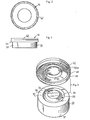
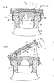
- An overall designated 10 closure (z. B. Fig. 1 to 9) for holding a plug 12 in an outlet 11 of a container, for. B. a bottle 14 shown in FIGS. 8 and 9, a cap 29.
- the stopper 12 has in the usual way a stopper part 18 provided with an inner cavity 26, which fits tightly into the opening 11 of the bottle, and an upper upper part 22, which covers the mouth 24 of the bottle and rests against this mouth 24.
- the plug part 18 has the inner cavity 26 on the inside in order to have a thin-walled section 28 in the central region, which, for. B. can be pierced with the needle of a subcutaneous syringe to get to the bottle contents.
- the plug 12 can have any conventional shape; the present invention does not relate to the particular design of the plug.
- the throwing capsule 29, which holds the stopper 12 is preferably made of sheet metal, for. B. made of aluminum sheet and is cup-shaped with an upper part 30 and a lateral jacket, the lower edge of the jacket 32 is crimped under the mouth bead 33 of the bottle 14 to hold the cap 29 and the stopper 12.
- the upper part 30 has a somewhat protruding, bowl-shaped, central disk part 34, which is connected to an annular outer part 36 of the upper part 30 via a somewhat recessed, circular recess 38.
- the central disc part 34 is detachably or separably connected to the annular outer part 36 and in the present case by a continuous, circular notch 39, which is formed in the outer surface 40 of the recess 38, and a circular predetermined breaking zone, in which the throwing capsule 29 has a smaller one Thickness T S has.
- the closure arrangement further includes a cover part 42, preferably made of a plastic material, such as polypropylene, which is connected to the central pane part 34. As shown in FIG. 9, this disc part can be lifted on its edge 44 on the outside with the thumb in order to separate the attached central disc part 34 from the remaining capsule along the notch 39 so that the stopper for removing the bottle contents is exposed by means of a syringe is.
- the lid portion 42 is attached to the detachable disc portion 34 of the cap, such that the closure is hermetically sealed, the capsule 29 holding the stopper and forming an assembly that is simple and economical to manufacture.
- the outer surface of the cap 29 is provided with a thin material layer 45 of predetermined thickness T pp at least in the region of the upstanding, removable disc part 34, which is connected to the outer surface of the cap by means such as. B. heat or the use of an adhesive and which is connected to the cover part 42 by application of heat and / or pressure. It has been found that a layer of polypropylene is suitable for this purpose.
- the lid part as shown in Fig.
- the cover part 42 has a disc-like shape with a short, approximately radially directed flange 46 on the outer peripheral edge of the upper part, with a rounded, inner transition 48 is provided on the inside to adapt to the upper edge of the cap.
- the cover part 42 also has a circular, projecting flange 50 which delimits a cavity 50 a, which is adapted to the contour of the projecting disc part 34 of the upper part of the cap.
- the large connection area between the cover part 42 and the disc part 34 of the cap capsule provides a high connection strength in order to tear off the disc part 34 of the cap capsule along the partial indentation 39 when actuated by rotating or lifting the cap part away from the cap, as shown in FIG. 9 , to guarantee.
- the diameter D of the notch 39 is in particular smaller than D of the connecting surface x.
- the connection area between the lid and the cap can be changed depending on the capsule size and the depth of the notch can also be changed so that the pulling force can be adjusted within a predetermined range.
- the bond between the cover 42 and the throwing capsule is in all cases greater than the force for separation at the predetermined breaking point formed by the notch 39 in order to ensure the removal of the disk part 34 from the cap capsule when the cover part 42 is pulled off.
- the depth of the notch is such that the disc part 34 of the capsule does not break prematurely during handling; in this way it survives various treatment techniques during the manufacturing process and is still relatively easy to remove when put into use.
- the lid 42 and the capsule 29 are practically self-centering due to the bulging structure of the coupling capsule and the cavity 50 a, which is delimited in the lid part 42 by the flange 50, so that the lid and the capsule are simple and accurate in automatic, quickly lukewarm feeding and assembly systems can be treated.
- the closure arrangement according to the present invention is simple and economical to manufacture.
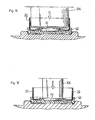
- circular disks made of polypropylene-coated aluminum can be cut out of flat sheet stock and shaped into the desired structure of the capsule in one molding process, such as, for example, B. shown in Fig. 4. 14-17, the notch 39 is then molded into the molded capsule by e.g. B. is inserted into an upper punch 200 which moves back and forth against a lower groove shape or groove head 202 with a cutting edge 203.
- the capsule provided with a notch 39 is then ready to be attached to the lid part 42, which can be done by a hot joining process as shown in FIGS. 15 and 16 or an ultrasonic joining process as in FIG. 17 shown, can be performed.
- the cover part 42 is held in a centering part 205.
- the capsule is then placed in the appropriate position in the cover part.
- An electric heating element 204 which has a shaped middle part 204 a corresponding to the middle, detachable disc part of the capsule, is then placed on the inside of the capsule, as shown in FIG. 16, in order to achieve the desired binding force between the middle zone under pressure and heat To reach the lid part and the outer polypropylene layer of the capsule 29.
- the part of the cover part which lies radially outside the notch is slightly lifted off the outer, annular upper part 30 of the coupling capsule 29 in order to prevent the cover part from adhering to the capsule in this area or in this zone .
- closure 17 is essentially the same, except that in this example an ultrasonic head or tool 206 is used which only heats the removable disc part to achieve the desired localized adhesion of the lid part only to the disc part of the capsule , which lies radially inward from the notch 39.
- the closure is then ready to be placed on a filled container by simply placing it in position over the stopper and crimping the bottom edge under the mouth bead 33 of the container or bottle.
- the cap can also be covered with a polypropylene varnish. It is of course also possible to coat the metal cap with other hot melt adhesives commercially available.
- connection surface X ' is determined by the width of the surface 70 of the flange of the cap.
- This area X ' can be comparatively small in order to obtain an acceptable operating force if the connection is disconnected by pulling off the cover part 66 in the manner described above, so that the plug area 12 is exposed, by means of a subcutaneous syringe to the contents of the container to get.
- This closure arrangement can also be produced simply and economically.
- the closure assembly also has all the advantages of the main application described above, in that it creates a hermetic seal between the closure and the plug and is really tight due to the fact that once the connection between the flange 68 of the lid member 66 and the surface of the cap capsule is separated that could only be restored by applying heat and pressure.
- the polypropylene-coated union capsule 80 similar to the embodiment in FIG. 10, has a circular opening 82 in the upper region 84.
- the outer plastic layer 86 is circularly provided with a groove 96, offset radially outward from the opening in the upper area of the coupling capsule 80.
- the cover part 97 has an axially projecting, stepped projection 90 with a central one Stopper part 92, which engages tightly in the circular opening 82 of the cap.
- the groove 96 is formed only in the plastic layer 86 and the cap 80, which should preferably be aluminum, has no notch and is generally uniform in thickness.
- the connecting surface X "lies within the groove 96 in the plastic layer 86 of the coupling capsule, so that when the cover part is removed to separate the connection, the ring-like plastic band breaks off neatly at the groove 96 and adheres to the cover part
- the sealing surface X can optionally be changed depending on the size of the closure arrangement, so that a connecting force is present which connects the cover part and the cap capsule sufficiently and is greater than the force required to break the notch 96 is required.
- the engagement of the plug member 92 in the opening facilitates proper alignment of the parts during the connection process.
- Fig. 12 shows a shutter arrangement which is similar in operation and function to the main application example.
- the upper portion 100 of the cap capsule 102 is relatively flat and includes a partial score line 104 that extends through the
- Plastic layer 106 and partially extends into the upper aluminum portion 100 to determine a removable washer 111.
- the lid part 110 has a central projection 112 with a diameter D 3 that is smaller than the diameter D 4 of the disk 111, which is determined by the notch 104.
- the lid element is connected to the cap capsule by applying heat and pressure in the manner described above over this area of the surface of the projection designated X '". In this case, by actuating the cover part, the cap capsule breaks along the notch, thereby increasing the connecting force in the area X ′′ ′′, where the cover is connected to the layer, is greater than the force required to break the disk 111 along the partially grooved score line 104.
- FIG. 13 is similar to that in FIG The illustrated embodiment is shown except that here the upper part 120 of the throwing capsule 122, which is provided with a plastic layer 123 adhering therein, has a flat, drawn-in region 124, and that the projection 126 on the cover part 128 has a correspondingly shaped part , Complementary guide member 130 which sits in the rounded cavity in the coupling capsule.
- the connecting force that the Cover part with the throwing capsule ensures in the area designated X ", greater than the force necessary to break the central disc part 135, which is delimited by the notch 134.
- the cover part and the disc part 135 are removed, they remain attached to one another and a central opening is formed in the throwing capsule.
- the notch 134 penetrates the plastic layer 123 and the upper part 120 of the coupling capsule; the contents of the container can then be accessed using a subcutaneous syringe.
- the drawn area 124 of the washer part 135 align the parts precisely for the joining process.
- lid member and the capsule of the application examples in Figures 10 to 13 can generally be assembled and connected to form a complete unit as described in connection with the main application example and as shown in the figures 14 to 17 shown schematically.
- closures according to the present invention are a metal capsule made of easily deformable aluminum with a plastic coating e.g. B. from polypropylene, the capsule can also be made of other material such. B. different versions of plastic material that can be connected by ultrasound or other means to the lid part in the manner described above to achieve the desired, delimited connection of the lid part and the capsule.
Landscapes
- Engineering & Computer Science (AREA)
- Mechanical Engineering (AREA)
- Closures For Containers (AREA)
- Closing Of Containers (AREA)
Applications Claiming Priority (2)
| Application Number | Priority Date | Filing Date | Title |
|---|---|---|---|
| US47568983A | 1983-03-14 | 1983-03-14 | |
| US475689 | 1983-03-14 |
Publications (2)
| Publication Number | Publication Date |
|---|---|
| EP0120353A2 true EP0120353A2 (fr) | 1984-10-03 |
| EP0120353A3 EP0120353A3 (fr) | 1985-07-03 |
Family
ID=23888684
Family Applications (1)
| Application Number | Title | Priority Date | Filing Date |
|---|---|---|---|
| EP84102341A Withdrawn EP0120353A3 (fr) | 1983-03-14 | 1984-03-05 | Fermeture pour récipient, en particulier flacons pharmaceutiques, ainsi que la méthode pour la fabrication d'une telle fermeture |
Country Status (8)
| Country | Link |
|---|---|
| EP (1) | EP0120353A3 (fr) |
| KR (1) | KR840007997A (fr) |
| AU (1) | AU579814B2 (fr) |
| DK (1) | DK138084A (fr) |
| ES (5) | ES287294Y (fr) |
| FI (1) | FI841036L (fr) |
| NZ (1) | NZ207437A (fr) |
| PT (1) | PT78251B (fr) |
Cited By (7)
| Publication number | Priority date | Publication date | Assignee | Title |
|---|---|---|---|---|
| WO1988006556A1 (fr) * | 1987-03-06 | 1988-09-07 | Pharma-Metall Gmbh | Couvercle pour recipients, en particulier flacons utilises en pharmacie |
| EP0388769A1 (fr) * | 1989-03-23 | 1990-09-26 | Pharma-Gummi Wimmer West GmbH | Dispositif de bouchage pour bouteilles contenant des produits pharmaceutiques et procédé pour sa fabrication |
| EP0675830A4 (fr) * | 1992-12-30 | 1997-12-29 | Abbott Lab | Bouchon a fine membrane pour dispositif penetrant non pointu. |
| WO2013149844A1 (fr) * | 2012-04-03 | 2013-10-10 | Datwyler Pharma Packaging International Nv | Procédé de fabrication d'un bouchon à collerette, bouchon à collerette et récipient muni d'un bouchon à collerette |
| DE102010038031B4 (de) * | 2010-10-07 | 2017-01-26 | Helvoet Pharma Belgium N.V. | Verfahren zur Herstellung einer Bördelkappe, Bördelkappe und Behältnis |
| US9585811B2 (en) | 2011-10-11 | 2017-03-07 | Datwyler Pharma Packaging Belgium Nv | Method for producing a crimp cap, crimp cap and container |
| EP3995123A4 (fr) * | 2019-07-02 | 2023-08-09 | Taisei Kako Co., Ltd. | Capuchon et flacon avec capuchon |
Family Cites Families (4)
| Publication number | Priority date | Publication date | Assignee | Title |
|---|---|---|---|---|
| US3071274A (en) * | 1961-04-04 | 1963-01-01 | West Co | Cap structure for bottles |
| CH475137A (de) * | 1964-06-26 | 1969-07-15 | Albis Pack Ag | Dose mit an ihr befestigter Verschlussmembran. |
| JPS5749739Y2 (fr) * | 1978-08-25 | 1982-10-30 | ||
| DE3130246A1 (de) * | 1981-07-31 | 1983-02-24 | Fritz Wünnerlein & Co., 8502 Zirndorf | "flaschenverschluss" |
-
1984
- 1984-02-29 DK DK138084A patent/DK138084A/da not_active Application Discontinuation
- 1984-03-05 EP EP84102341A patent/EP0120353A3/fr not_active Withdrawn
- 1984-03-08 AU AU25394/84A patent/AU579814B2/en not_active Ceased
- 1984-03-08 NZ NZ207437A patent/NZ207437A/en unknown
- 1984-03-13 ES ES1984287294U patent/ES287294Y/es not_active Expired
- 1984-03-13 KR KR1019840001254A patent/KR840007997A/ko not_active Ceased
- 1984-03-14 PT PT78251A patent/PT78251B/pt unknown
- 1984-03-14 FI FI841036A patent/FI841036L/fi not_active Application Discontinuation
-
1985
- 1985-12-02 ES ES1985290680U patent/ES290680Y/es not_active Expired
- 1985-12-02 ES ES1985290679U patent/ES290679Y/es not_active Expired
- 1985-12-02 ES ES1985290677U patent/ES290677Y/es not_active Expired
- 1985-12-02 ES ES1985290678U patent/ES290678Y/es not_active Expired
Cited By (8)
| Publication number | Priority date | Publication date | Assignee | Title |
|---|---|---|---|---|
| WO1988006556A1 (fr) * | 1987-03-06 | 1988-09-07 | Pharma-Metall Gmbh | Couvercle pour recipients, en particulier flacons utilises en pharmacie |
| EP0388769A1 (fr) * | 1989-03-23 | 1990-09-26 | Pharma-Gummi Wimmer West GmbH | Dispositif de bouchage pour bouteilles contenant des produits pharmaceutiques et procédé pour sa fabrication |
| EP0675830A4 (fr) * | 1992-12-30 | 1997-12-29 | Abbott Lab | Bouchon a fine membrane pour dispositif penetrant non pointu. |
| DE102010038031B4 (de) * | 2010-10-07 | 2017-01-26 | Helvoet Pharma Belgium N.V. | Verfahren zur Herstellung einer Bördelkappe, Bördelkappe und Behältnis |
| US9585811B2 (en) | 2011-10-11 | 2017-03-07 | Datwyler Pharma Packaging Belgium Nv | Method for producing a crimp cap, crimp cap and container |
| WO2013149844A1 (fr) * | 2012-04-03 | 2013-10-10 | Datwyler Pharma Packaging International Nv | Procédé de fabrication d'un bouchon à collerette, bouchon à collerette et récipient muni d'un bouchon à collerette |
| EP3995123A4 (fr) * | 2019-07-02 | 2023-08-09 | Taisei Kako Co., Ltd. | Capuchon et flacon avec capuchon |
| US12115127B2 (en) | 2019-07-02 | 2024-10-15 | Taisei Kako Co., Ltd. | Cap and capped vial |
Also Published As
| Publication number | Publication date |
|---|---|
| ES287294Y (es) | 1987-04-01 |
| DK138084D0 (da) | 1984-02-29 |
| EP0120353A3 (fr) | 1985-07-03 |
| ES290679U (es) | 1986-04-16 |
| ES290678U (es) | 1986-04-16 |
| ES290679Y (es) | 1986-12-01 |
| ES290678Y (es) | 1986-12-01 |
| ES287294U (es) | 1986-05-01 |
| NZ207437A (en) | 1987-06-30 |
| AU2539484A (en) | 1984-09-20 |
| ES290680U (es) | 1986-04-16 |
| DK138084A (da) | 1984-09-15 |
| ES290677U (es) | 1986-04-16 |
| PT78251B (en) | 1986-04-22 |
| FI841036A0 (fi) | 1984-03-14 |
| AU579814B2 (en) | 1988-12-15 |
| FI841036A7 (fi) | 1984-09-15 |
| ES290677Y (es) | 1986-12-01 |
| ES290680Y (es) | 1986-12-01 |
| FI841036L (fi) | 1984-09-15 |
| KR840007997A (ko) | 1984-12-12 |
| PT78251A (en) | 1984-04-01 |
Similar Documents
| Publication | Publication Date | Title |
|---|---|---|
| EP0364783B1 (fr) | Fermeture pour une bouteille à usage médical et son procédé de préparation | |
| DE69021739T2 (de) | Behälterverschluss und verfahren zu seiner herstellung. | |
| DE10127823C1 (de) | Verschluss für eine Medikamentenflasche sowie Verfahren zu dessen Herstellung | |
| DE3244459A1 (de) | Behaelter mit deckel | |
| DE3028281C2 (de) | Verschlußanordnung für pharmazeutische Behälter | |
| EP0883550B1 (fr) | Dispositif pour ouvrir et refermer des recipients | |
| EP2834161A1 (fr) | Procédé de fabrication d'un bouchon à collerette, bouchon à collerette et récipient muni d'un bouchon à collerette | |
| DE2727737C2 (de) | Bördelkapsel | |
| DE2108061A1 (de) | Behalter mit angeformtem Verschluß aus Kunststoff | |
| EP0120353A2 (fr) | Fermeture pour récipient, en particulier flacons pharmaceutiques, ainsi que la méthode pour la fabrication d'une telle fermeture | |
| EP0098810A2 (fr) | Fermeture de garantie pour bouteilles | |
| DE69327477T2 (de) | Saugereinheit und verfahren zur herstellung der saugereinheit | |
| EP0712787A1 (fr) | Récipient avec ouverture de distribution fermée par un ruban | |
| DE69909844T2 (de) | Leicht zu öffnende haube | |
| EP0209031B1 (fr) | Boîte, ainsi que le procédé et la membrane pour sa fermeture | |
| DE2361350B1 (de) | Verschluß für pharmazeutische Flaschen | |
| DE1532404A1 (de) | Behaelterdeckel mit einem durch Aufreissen leicht zu oeffnenden Aufreissbereich | |
| DE2647775A1 (de) | Vorrichtung zum loesbaren verschliessen der offenen stirnseite eines rohrfoermigen behaelters | |
| EP0735976A1 (fr) | Dispositif pour l'ouverture d'un emballage | |
| DE69213211T2 (de) | Behälterverschluss mit Abreissband | |
| DE2809855A1 (de) | Aufbrechbarer behaelterverschluss, verfahren zu seiner herstellung und damit ausgestatteter behaelter | |
| EP0758989B1 (fr) | Bouchon a bande de garantie | |
| EP0388769A1 (fr) | Dispositif de bouchage pour bouteilles contenant des produits pharmaceutiques et procédé pour sa fabrication | |
| DE19629148C2 (de) | Verfahren zur Herstellung eines befüllten Behälters | |
| EP0601283B1 (fr) | Capsule pour une bouteille à médicaments |
Legal Events
| Date | Code | Title | Description |
|---|---|---|---|
| PUAI | Public reference made under article 153(3) epc to a published international application that has entered the european phase |
Free format text: ORIGINAL CODE: 0009012 |
|
| AK | Designated contracting states |
Designated state(s): AT BE CH DE FR GB IT LI LU NL SE |
|
| PUAL | Search report despatched |
Free format text: ORIGINAL CODE: 0009013 |
|
| AK | Designated contracting states |
Designated state(s): AT BE CH DE FR GB IT LI LU NL SE |
|
| 17P | Request for examination filed |
Effective date: 19850531 |
|
| 17Q | First examination report despatched |
Effective date: 19860526 |
|
| STAA | Information on the status of an ep patent application or granted ep patent |
Free format text: STATUS: THE APPLICATION IS DEEMED TO BE WITHDRAWN |
|
| 18D | Application deemed to be withdrawn |
Effective date: 19861206 |
|
| RIN1 | Information on inventor provided before grant (corrected) |
Inventor name: CONARD, WILLIAM ALBERT Inventor name: HEISTAND, DAVID HAROLD Inventor name: CONNOR, JOHN THOMAS |