EP0120387B1 - Procédé et appareil pour la représentation vectorielle de documents et la reconnaissance de symboles - Google Patents
Procédé et appareil pour la représentation vectorielle de documents et la reconnaissance de symboles Download PDFInfo
- Publication number
- EP0120387B1 EP0120387B1 EP84102683A EP84102683A EP0120387B1 EP 0120387 B1 EP0120387 B1 EP 0120387B1 EP 84102683 A EP84102683 A EP 84102683A EP 84102683 A EP84102683 A EP 84102683A EP 0120387 B1 EP0120387 B1 EP 0120387B1
- Authority
- EP
- European Patent Office
- Prior art keywords
- vector
- data
- run
- coordinates
- scan line
- Prior art date
- Legal status (The legal status is an assumption and is not a legal conclusion. Google has not performed a legal analysis and makes no representation as to the accuracy of the status listed.)
- Expired - Lifetime
Links
Images








Classifications
-
- H—ELECTRICITY
- H04—ELECTRIC COMMUNICATION TECHNIQUE
- H04N—PICTORIAL COMMUNICATION, e.g. TELEVISION
- H04N1/00—Scanning, transmission or reproduction of documents or the like, e.g. facsimile transmission; Details thereof
- H04N1/41—Bandwidth or redundancy reduction
- H04N1/411—Bandwidth or redundancy reduction for the transmission or storage or reproduction of two-tone pictures, e.g. black and white pictures
- H04N1/413—Systems or arrangements allowing the picture to be reproduced without loss or modification of picture-information
- H04N1/417—Systems or arrangements allowing the picture to be reproduced without loss or modification of picture-information using predictive or differential encoding
-
- G—PHYSICS
- G06—COMPUTING OR CALCULATING; COUNTING
- G06V—IMAGE OR VIDEO RECOGNITION OR UNDERSTANDING
- G06V10/00—Arrangements for image or video recognition or understanding
- G06V10/20—Image preprocessing
-
- G—PHYSICS
- G06—COMPUTING OR CALCULATING; COUNTING
- G06V—IMAGE OR VIDEO RECOGNITION OR UNDERSTANDING
- G06V10/00—Arrangements for image or video recognition or understanding
- G06V10/20—Image preprocessing
- G06V10/32—Normalisation of the pattern dimensions
-
- G—PHYSICS
- G06—COMPUTING OR CALCULATING; COUNTING
- G06V—IMAGE OR VIDEO RECOGNITION OR UNDERSTANDING
- G06V10/00—Arrangements for image or video recognition or understanding
- G06V10/40—Extraction of image or video features
-
- H—ELECTRICITY
- H04—ELECTRIC COMMUNICATION TECHNIQUE
- H04N—PICTORIAL COMMUNICATION, e.g. TELEVISION
- H04N1/00—Scanning, transmission or reproduction of documents or the like, e.g. facsimile transmission; Details thereof
- H04N1/41—Bandwidth or redundancy reduction
- H04N1/411—Bandwidth or redundancy reduction for the transmission or storage or reproduction of two-tone pictures, e.g. black and white pictures
- H04N1/4115—Bandwidth or redundancy reduction for the transmission or storage or reproduction of two-tone pictures, e.g. black and white pictures involving the recognition of specific patterns, e.g. by symbol matching
Definitions
- This invention relates to devices and methods for compactly converting planar drawings to coded digitized information for subsequent storage, printing and editing, and to such devices used for symbol learning and recognition.
- Digital coding of graphic information is commonly called for in a wide variety of contexts for facsimile data transmission to computerized photograph analysis and patterns recognition, to computer-aided design applications.
- the first step in such digitizing is to scan the document in a controlled fashion, measuring the graphic value of the image at each point.
- Currently available scanning devices are capable of substantially simultaneously delivering a binary output signal for each of n lines of resolution cells, each cell being approximately .01 mm square.
- a one meter long scan line of engineering drawing for example would contain 10 5 such resolution cells; a single square centimeter would contain 16 6 resolution cells.
- the digitized information is in the form of raster output data from .01 mm resolution cells
- a typical 80 character alphabetic line might then be coded as approximately 200 information signals for each 20 cm long scan line, a reduction of 99 percent compared to the 2 X 10 4 bits of raw raster output data.
- a sheet of A4 paper contains 6 X 10 8 such resolution cells, it can be seen that such a coding is still very cumbersome, requiring over a million information signals to code a single page of bitonal writing, scan line by scan line.
- This inefficiency is addressed in the prior art by a number of techniques which look for broader patterns by correlating the run length compressed data across a second dimension, typically by comparing contiguous adjacent scan line data and coding the difference.
- the present invention is set out in the appended claims. It overcomes the foregoing limitations by real-time processing of raster scan information using data maintained in a small memory describing each significant graphic element, or vector, which has been encountered in the preceeding M scan lines.
- the "vectorized" description in memory includes functions of two coordinates, such as center line and width, which locally represent the graphic element as a trapezoid. As the document is scanned, these vector descriptions in memory are continuously updated and the descriptive parameters refined.
- a compactly coded lector description is sent as an output, together with a code signal indicating the presence of a branch point with another vector if applicable, and the corresponding address in memory is freed up to accommodate another vector.
- a number of parallel arithmetic logic units compare a scan line intercept or run with a vector in memory, and no additional coding is performed unless new information is encountered. The entire coding process is done as a single pass operation, at a speed comparable to the scan speed, yet putting out enormous compact data.
- the device would, upon passing M scan lines below the bottom of the triangle without encountering any continuing vector, cause to be produced as an output a code indicating the vector had terminated, the address in memory of the vector parameters, and its last encountered left and right edge coordinates.
- the data in memory would include the coordinates of the top of the triangle, and two linear functions describing its center line and width. (The ending scan line number would automatically be registered on a common synchronizing bus for various components of the system.)
- fewer than ten integers would fully describe a figure which in the case say of a three centimeter tall triangle with an area of 10 square centimeters would include 10' resolution cells spanning 3 X 10 3 scan lines.
- the output would contain similarly compressed data representing the figure by numerical parameters giving a linear geometric approximation by included trapezoids.
- the apparatus includes a keyboard-selectable means of varying the integer parameter M which determines the number of scan lines which a "missed" vector will be held in memory before it is recognized as terminated and caused to be output.
- the preferred embodiment also includes a keyable thresholding means, in which the user selects an upper and lower threshhold limit (MINTRO and MAXTRO) for the dimensions of images the machine will recognize as noise ⁇ e.g. line edge irregularities, ink spots or voids.
- the apparatus then varies an intermediate threshold testing parameter between the two limits as a function of the dimensional traits of the vector under consideration near a particular scan line, so as to optimize the parameterization of the vector within a small number of scan lines, while rejecting as noise any information contained in runs smaller than the threshold level.
- the apparatus sorts the vectorized images by dimensional and topological criteria to identify symbol candidates, determines the center of mass and maximum extremity of the symbol candidate, and transposes the candidate to a standard orientation and scale. The normalized candidate is then recognized by comparison to a preselected or learned library of symbols.
- the present invention takes raster output data and concurrently converts it into compactly coded data representative of raster scanned graphical element in an image as an approximation including one or more trapezoids, and storing the parameters of trapezoids so describing currently intercepted portions of the image in a memory.
- Each trapezoid in the approximation of the image is referred to in this description may have "width” as well as longitudinal orientation, but the term “vector” in the claims herein is not intended to be limited only to this special case.
- Input raster data related to a given small region is then compared to memory data for nearby regions and relevant information relating thereto is encoded.
- the memory data, for each vector, includes an ordered block of information derived from processing prior scan intercepts of the related graphic element. This block of information is also sometimes called below a "vector".
- the first stage in processing labelled INITIALIZING PROCESSING in Figure 1
- the second major stage depicted in Figure 1 is the real time processing stage. During this stage, binary raster output data is fed, via a data compression interface unit, of the processor. The processor then sequentially compares the incoming segments of raster data with vectorized information in its memory, developing an output when necessary.
- TERMINATION PROCESSING When the processor determines that a given vector resulting from raster data is terminated at a given scan line, an output is made; however, a graphic element may continue as a single vector to the end of the document being scanned. Accordingly, in a final stage, denoted TERMINATION PROCESSING in Figure 1 the device forces outputs for those vectors which have not already terminated, and gives appropriate termination signals to other units of the apparatus.
- a subscript R 2 refers to the edge data from the vector in the J-register, which will normally be the edge data from a previous scan of the graphic element related to the I or 1+1 register run.
- the subscript RO when used with the quantities C, E or S denotes the value of the center, extent or scan line number respectively of a memory vector at the scan line where that vector record commences; when used with the threshold function T, T RO denotes the last-computed value of the threshold function T, which is updated each time the center and edge predictor slopes are refined, as will be further- explained with reference to Figure 6.
- Vector number 0 is defined as a zero width vector with right hand edge has coordinate -s. This is a sentinel vector with fictitious or impossible coordinates, used to designate the left hand side of the document.
- the next vector, vector number 1, is also a fictitious sentinel vector, and is defined in the third box down, as one having its left and right edges at scanner resolution element number 65,000. This is a vector of zero width located at the right hand edge of the document, the number 65,000 corresponding to the case of a document having a 65,000 resolution cell scan line width.
- the remainder of the steps shown in the left hand column of Figure 2 amount to establishing a numerical order of the addresses in the random access memory.
- this memory accommodate 2'° words, each word being 188 bits long. It has been found that a memory of this size is generally more than adequate for the processing of even very dense engineering drawings.
- the device is set for scan line zero at the left hand side, and signals are output to prepare the output processor for receiving data and to initiate input of data from the data compression box.
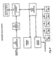
- FIG. 3 there is shown a block diagram of the vectorizer according to the present invention, in which scanner input is fed to a data compression circuit 31 which extracts, from each run of like-valued bits, the coordinates of the center point, C, the scalar extent E or half-width of the run, and the coordinates of the left edge Land right edge R of the run.
- this information is redundant, inasmuch as the first two values may be computed from the second two, but as a practical matter the creation of an ordered 4-tuple of data values for each input run or segment can be done in real time at the input stage, and doing so avoids greater complexity in the later processing.
- the ordered (C, E, L, R) information is fed to an INPUT BUFFER 32 which contains two registers denoted I, 1+1, which hold compressed (C, E, L, R) data related to two consecutive input segments.
- the device processes the information in the input buffer by sequentially comparing coordinates of input segments to a corresponding "vector record" held in a vector memory 33 and temporarily loaded into a single register 34 called the J register.
- a common multibus structure 36 connects the various registers to a plurality of arithmetic logic units shown as 35a-35e so as to deliver corresponding center or edge coordinates of segments being processed to the ALUs 35a-35e.
- the use of multiple ALUs and a multibus structure together allow numerous arithmetic comparisons on different sets of coordinates to be carried out in parallel, so that relevant dimensional and topological data may be quickly ascertained.
- the J register 34 as noted is loaded at a given time with a vector record from the memory 33.
- Each record is an ordered string of words derived from the processing of previous input segments, and contains in addition to the edge coordinates intercepted by the most recent scan line a variable threshold number T RO , which governs processing parameterization steps, the original scan line number S RO with which the record commences, the linear predictor functions DE and DC from which the center point and half-width or extent of the input may be predicted.
- T RO variable threshold number
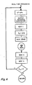
- FIG. 4 there are shown the steps involved in REAL TIME PROCESSING. Initially the scan line is incremented by one, and a 16-bit binary word is output to the output processor indicating this increment.
- the next input to the I register which generally receives the center, extent and edge coordinates of the next scan line intercept from the data compression module, is loaded, and inasmuch as the I registers will initially contain irrelevant material such as the right hand sentinel vector or the left hand sentinel vector for the new scan line, the right edge is arbitrarily set to -e. This flushes the I registers and prepares the processor for NEXT STAGE processing, shown in Figure 6.
- the NEXT STAGE processing is a sorting step, in which the information in the I register is processed by the parallel arithmetic logic circuitry in an acceptably short time. As noted before, the coding process occurs in real time and must be accomplished at substantially the same rate as scanner data is fed into the system.
- a given vector intercept is determined to be one of the following: a branch of a lambda junction, a trunk of a Y junction, a new segment, or a simple overlap (also called a continuation) of an existing vector.
- the determination as to which one of the above four topological and geometric properties applies is made by performing simple arithmetic tests upon the left and right edges of a vector from memory (held in the J register) and an input record from the data compressor, held in the I or 1+1 register. These arithmetic comparisons are done in parallel by four of the arithmetic logic units 35(a)-(e) shown as ALU1-ALU5 in Figure 3; the timing signals from a timing control unit causing the appropriate edge coordinates to be automatically delivered to the ALU along busses for such processing.
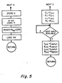
- FIG. 5 which indicates the processing denoted NEXT I, it can be seen that the center, extent, left and right edge coordinates in the 1+1 register are transferred to the I register, and if there is an input available from the data compression unit, then the coordinates of the center, extent, and left and right edges of the next available input are loaded into the 1+1 register. In this manner there are always available the C, E, L and R data for the next two intercepts along a scanned line for processing by the processor.
- the processor has available in the J register a complete vector record, comprising 188 bits more or less of information as will be more specifically outlined below.
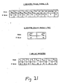
- This J register record shown in Figure 21 is the most recently updated record for a particular vector in the main memory.
- This main memory record contains predictive parameters for the vector under consideration as well as the scan line number where it first appeared and its last measured center, extent and left and right edges, all of which will be loaded into the J register at a given time for processing of input data from intercepts below it in the next subsequent scan line.
- This vector from main memory is referred to generally as a "superadjacent vector" in relation to graphic intercepts directly or contiguously below it and for which it may constitute a connected portion of a continuation or a Y or lambda member.
- the active vector segments in the memory are continuously re-ordered in a forward link-list during processing so that the processor addresses them in the order they are encountered, from left to right, so that there will be at most two "superadjacent" vectors for a given intercepted segment.
- FIG. 5 Also shown in Figure 5 is the NEXT V processing.
- V is set equal to the next vector in memory, which is loaded into the J-register.
- the quantity RSAVE a temporary processing number equal to plus the right hand coordinate of the vector is saved, and the next vector NV is loaded into the K register. (The quantity RSAVE is next used in a simple coordinate comparison to detect whether a branch point has been scanned.)
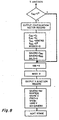
- FIG. 6 there is shown the stage of processing designated NEXT STAGE processing, in which edge data for the vector, or vector intercepts in the J, or I, and 1+1 registers respectively are selectively compared by four parallel arithmetic units and, according as the respective arithmetic inequalties are true or false, is fed into a subsequent processing stage as indicated in the six bores on the right hand side of Figure 6.
- Inspection of the logic diagram of Figure 6 reveals that for a given geometrical configuration, the arithmetic comparison tests outlined in the flow diagrams of the left hand column will lead to one and only one of the process boxes in the right hand column of Figure 6.
- the top left hand logic test indicates that only if the left edge of the 1+1 input is not greater than the right edge coordinate RSAVE is the intercept represented in the 1+1 register processed and coded as an L-junction.
- the quantity RSAVE is defined to be initially -e, and generally is equal to the right hand edge of the vector in the J register plus s.
- the second logic branch box only if the left hand edge of the next vector to be loaded in the J register is not greater than the right hand edge of the I intercept vector plus e, and it has passed the preceeding test does the I register intercept get processed as the trunk of a Y junction.
- the K register since only the current left and right edge coordinates of the next vector are needed for branching tests, these coordinates are loaded into a small register, the K register, to be available for this processing.
- the contents of the K register are shown in Figure 21.
- SIMPLE OVERLAP or continuation
- the processing appropriate for each one of these six determinations is shown in Figures 7 to 12 only one of which processing stages will be activated for a given input.
- Figure 7 there are shown the processing steps for the scan line intercepts from register 1+1 when the arithmetic comparison tests of Figure 6 have determined the input to be a lambda-JUNCTION. In this event, the extent of the input is first checked to be greater than a preset minimum extent.
- the term "extent”, represented by E with an identifying subscript, is used throughout this disclosure to refer to one-half of the width of a run.
- a rounding-off convention is arbitrarily established to assure integral coordinates for the center point and the extent of a run.
- the scalar quantity MINEXT of Figure 7 is a preselected number which acts as a threshold for screening out certain kinds of noise that would otherwise be processed as branch point indicating data. For example certain graphic reproduction processes create microscopic streamer lines of dark density along a dark edge. Such noise may be eliminated from the further level processing steps.
- the choice of MINEXT may also be dictated by the knowledge that a drawing contains only, e.g., lines of a certain minimal thickness.
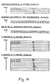
- MINEXT screens out all lesser-dimensional features, so that processing time will not be used to process such noise. If it does not satisfy this threshold requirement it is disregarded, the next input is loaded and the next stage processing is again commenced. On the other hand, if the extent of the 1+1 intercept is larger than MINEXT then the device determines whether the present scan line is the first scan line on which this vector appeared. If not, an output continuation vector record is produced, whereby the description of the vector as far down as the branch point is sent as an output (typical output records are shown in detail in Figures 14-15), and the new vector data for the left leg of the lambda replaces the former vector data in the memory.
- the quantities C, E and S in the J register are temporarily saved as they will form part of the L-junction output record and the vector in the J register is given new C, E and S data descriptive of the branch of the L-junction being processed.
- the processor then takes the next input, gets a free vector address, and uses it to reorder the vectors in memory, in such a way as to start a new vector comprising the right leg of the lamda junction as the next sequentially addressed vector after the left leg, which has been coded as a continuation of its top part.
- An L-junction record Figure 14 is generated identifying the top vector and its relation to the right leg of the junction.
- the parameter "MISSED" is set to zero and the parameter T RO is set to MINTRO, as is done initially when commencing any new vector parametrization. The significance of this latter step will be discussed later in connection with Figures 11 and 12.
- FIG 8 there is shown a block diagram of the processing undertaken in the event that the arithmetic comparison testing of Figure 6 indicates a given intercept to be a Y-JUNCTION.
- a continuation vector record is sent as an output, as indicated in Figure 13 and the C, E, S, TRO, and MISSED data are put into the J register as a continuation of the upper left branch of the Y, thereby acquiring its memory address.
- This data is put back in main memory, an output Y-junction record is produced and the vectors are reshuffled so that the former right branch of the Y-junction is no longer in memory and existing vector records are again consecutively addressed.
- the processor then returns to NEXT STAGE processing of Figure 6.
- SIMPLE OVERLAP or continuation of a previously encountered superadjacent vector
- superadjacent refers to an unterminated vector encountered in a previous scan line and which is located so that its width to some extent overlaps or is next to the given intercept in x coordinates.
- SIMPLE OVERLAP processing commences by loading the next input, getting the next vector from memory, and undertaking the hole-filling processing (explained below in relation to Figure 12).
- the SIMPLE OVERLAP processing is the major information compressing step of vectorization and involves creating and refining a piece-wise linear approximation to the image represented by the consecutive scan line intercepts.
- the parameter DELS is set to be the number of scan lines between the present scan line and the scan line where the vector was initially encountered.
- the numbers DC and DE are the slopes respectively of linear function representing the center and the extent.
- T RO the threshold parameter, is set which indicates the degree of error which will be permissible in the vectorized approximation of the image scanned.
- the processor initially determines whether the extent of the intercept stored in the I register differs from the extent predicted from memory by more than T f ⁇ / 2, and if not whether the center of the I register intercept differs from the predicted center by more than T RO . In either case, if greater than two scan lines have elapsed since the vector was first encountered, the vector continuation record will be sent as an output and a new vector approximation will be commenced using the current data, with the new center, extent, and scan line as the relevant vector data, with the parameters TRO set to the minimum and MISSED set to 0 as will be explained in regard to Figures 11 and 12.
- the device performs an additional arithmetic check to determine whether the current scan line is 2" (n an integer) scan lines down from where the vector was initially encountered. If not, the current left and right edges are simply entered in the J register, the parameter MISSED is set to 0 and the apparatus proceeds to the NEXT STAGE processing. On the other hand, if the number of elapsed scan lines since commencement of the vector is a power of 2, then the lower left hand branch of the processing diagram is implemented and the parameters DC and DE are updated using present scan line data, to give a new estimate of the slope of the center line and the slope of the extent function.
- the threshold parameter is adaptive, so that when the graphic features being processed are less then twice the width of MAXTRO, a closer degree of accuracy will be required of the estimations. This allows the processor to very quickly code information encountered in thick images and yet to more delicately catch the detail of fine graphic images, and to more quickly establish its predictive parameters when commencing to code a new vector.
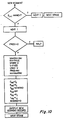
- FIG 10 there are shown the processing steps undertaken in the event the arithmetic sorting process of Figure 6 indicates the presence of a NEW SEGMENT.
- the input is disregarded, the next input loaded, and the processing shown in Figure 6 recommenced. Otherwise, the next input is loaded, and memory control is signaled to provide a free memory address for a new vector. If no memory address is available, as in the other processing steps wherein some shuffling of data in memory must be accomplished, the device halts.
- MISSING VECTOR processing A given vector is retained in main memory when a continuation input fails to appear for less then M scan lines.
- the parameter MISSED comprises one of the 12 words of data constituting the vector description carried in main memory as discussed below in connection with Figure 21; this parameter is updated by processing described presently.
- MISSED is less than a preselected number MAXMIS, the main memory vectorized description is retained and processing continues as usual, with the J-register edge and center predicters updated before returning to the memory as shown in the left branch of the processing diagram, Figure 11.
- FIG 12 there is shown the processing operation of HOLE FILLING.
- This step is only required during the processing of a SIMPLE OVERLAP, and operates on new inputs, I, 1+1, to delete runs of length less then T RO occurring in places where a run of another image value is predicted. Specifically, if the left edge of the 1+1 input is less than the right edge in the J register of the corresponding vector, and if the left edge of the 1+1 input minus the right edge in the I input is less than the threshold T RO , then the left edge coordinate in the I register is saved, the C, E and R contents of the 1+1 register loaded into the I register, and the next C, E, L and R coordinates from the data compression module are loaded into the 1+ register.
- the center and extent of the I register are redefined in accordance with L j and the new edge data R,. In this manner holes of dimension less than T RO are automatically filled. A feedback loop then returns the device to the start of the hole filling operation, and it again undergoes the first two tests. This will result in filling of additional holes, in the event that a number of ink spots or voids occur in close proximity within a sole vector.
- the record when a branch point such as a Y- (or lambda-) junction is encountered and the output record for the terminated right branch of the Y (or new right leg of the lambda) is generated, the record includes the address VMI of the top left (or top) branch as well as the address V of the portion scanned.
- the output record in the case of a Y- junction includes the left and right edge coordinates of the upper portion as well as the left and right edge coordinates from the I-register of the lower right portion.
- the record For a right leg of a lambda-junction, the record includes the scan jump, center and extent data for the upper portion.
- This data comprises the quantities SAVCRO, SAVERO and DELS defined in Figure 7.
- the particular choice of output records contains sufficient data regarding the topological and dimensional changes encountered so that by suitably programming an output processing device, it is possible to quickly print or access and display images generated by, e.g., a connected sub-unit depicted within a given drawing, or, for instance, the set of electrical circuit units connecting to a given component in an electrical schematic when analyzed according to this method.
- Figure 15 shows the steps involved in such processing. It will be appreciated that because the graphic elements encountered in a given scan line are vectorized and stored in memory, and there is no output of such data until a significant change has occurred requiring a new vectorization of subsequent continuations or branches, it is possible for a document to reach its last scan without having generated an output record indicative of a graphic element which, for instance, has continued as predicted, or which quite simply has not terminated by the last scan line.
- a termination processing mode which recognizes the last scan line by an externally triggered signal related to the document size, and proceeds to cause an output of an end-of-segment record for each of the vectors then left in memory.
- the operation of the foregoing coding device utilizes a relatively small memory for 188 bit words which can be addressed and fed into the J register by appropriate signals for processing in relation to the scan data being fed into the I and 1+1 registers.
- the various edge and center tests necessary for characterizing the current input and updating vector memory data are conducted in a straightforward way by parallel arithmetic logic units.
- parallel processing in this context constitutes part of the within invention, the design of arithmetic processing units is known to those versed in the art.
- the memory is managed in such a way as to contain a block of data descriptive of a small trapezoid which approximates the currently scanned region of the graphic element. Coding is performed, and processed data is updated or caused to be output, only when one of five information containing events (Y- or lambda-branch, new vector, continuation requiring a fresh trapezoid, or end of vector) is encountered.
- events which are the information- theoretic primitives of the present invention, are mutually distinct and are complete in the sense that any run of a scan line (which is not noise, or which is not already accurately predicted by the vector data for the region above it) must constitute one of these events.
- the first four events may be determined by simple arithmetic comparisons, and the fifth by default, so that it is a straightforward matter for a person versed in the art to design four arithmetic logic units which collectively and in parallel will determine which of the "events" characterizes a given run.
- the apparatus also performs symbol recognition on scanned documents in a manner explained below, using the vectorized representation to analyze the scanned symbol candidates, as will now be described.
- the coded data may be used to reproduce a facsimile document, which will be identical, except possibly for runs of up to MAXTRO resolution cells which have been filled or smoothed out.
- an output printer may be activated using the center line parameters (rather than the full two dimensional set of parameters), to print out a pseudocenter image of the document.
- a pseudocenter image includes the center line (or piecewise linear curve) of the graphic element.
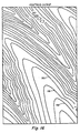
- Figure 16 is shown an image of the center lines 161 of a vectorized image such as a shaded topographical map.
- clusters which are possible symbols, for subsequent machine analysis.
- Such clusters may, for instance, be identified in terms of size and connectivity. For example, any isolated graphic element which together with all vectors connected thereto is between 1 cm. and 3 cm. in diameter would be a good candidate for recognition as an alphanumeric symbol. Similar criteria may be established in software to quickly identify small libraries of symbols for a given use-e.g. electronic components in circuit diagram; beam sections and fittings in structural engineering drawings.
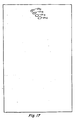
- Figure 17 shows the symbol candidates 171 a-d so extracted from the center line image of Figure 16.
- the apparatus calculates the center of mass of C from the vectorized representation of C. Specifically a local coordinate system is established and for each trapezoid T, included in the vector representation of C there are calculated a mass M equal to the area of the trapezoid, and coordinates (X,, Y,) equal to the center of mass of T computed as though T, were composed of a sheet of material of uniform density.
- the mass M of symbol C is set equal to I M, and the center of mass CM is then computed from the first moments of the system of trapezoids around the X- and Y-axes.
- the center of mass CM of C then has coordinates
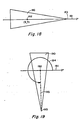
- This center of mass point (X, Y) has the property that the symbol C may be scaled with respect to (X, Y) and the resultant symbol will have the same center of mass (X, Y). Also the area (or mass M) of the symbol C is invariant with respect to rotation of C around the point (X, Y). [This latter property would of course hold for any point (X, Y).] Figures 18, 19 show a symbol in two different angular orientations about its center of mass.
- the apparatus next determines the point of C which is at a maximum distance from (X, Y).
- the point of C There may be a unique such extremity, as for the symbol "h”, several such points, as for the symbol "X”, or even a large number of such points, as for a circular "0".
- the point of extremity of a piecewise linear symbol candidate must be one of the vertices of the candidate, and accordingly for a vectorized image the point of extremity may be ascertained by simply examining the existing output data, computing the distance of each vertex from the center of mass, and taking the maximum one.
- Figure 18 is shown a symbol 180 aligned with its center of mass 182 and is extremity 183 along the X-axis 181.
- Figure 19 is shown a symbol 190 isomorphic to that of Figure 18 in a different orientation.
- the symbol 190 is shown having center of mass 192 and extremity 193.
- the center of mass 2 is placed at the origin, and the line segment 195 defined by endpoints 192 and 193 lies at an angle 194 with respect to the X-axis 191.
- the machine also "learns" the image of symbol as determined by each of the other extremities.
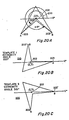
- Figures 20A-C show a symbol 200 having center of mass 202 and two extremities 203, 203'.
- the stored library of symbols which include two templates 210 and 220 representative of the symbol when it is shifted into the normal position with its center-extremity segment aligned with the x-axis.
- the machine in order to "recognize" a newly scanned symbol C', the machine takes the symbol candidate, C' and determines its center of mass CM' and extremity E', rotating it degrees into standard position.
- the candidate C' is then normalized and is compared to the library of learned symbols to determine the degree of overlap.
- This comparison which in the preferred embodiment is performed numerically (as is the rotation into standard form) amounts to measuring the degree of coincidence of the images of C and C' where C is a learned symbol from the library [Cj] of stored symbol images. This results in a sequence of measures ⁇ Xj ⁇ . (Xj:51) of the degree of coincidence between the candidate C' and each learned symbol C j in the library of stored images.
- the candidate C' is "recognized" as a particular symbol C m , when X m ⁇ J+m X j and X m is sufficiently large, say X m >T, a recognition threshold.
Landscapes
- Engineering & Computer Science (AREA)
- Multimedia (AREA)
- Physics & Mathematics (AREA)
- General Physics & Mathematics (AREA)
- Theoretical Computer Science (AREA)
- Signal Processing (AREA)
- Image Processing (AREA)
- Image Analysis (AREA)
- Character Input (AREA)
- Character Discrimination (AREA)
- Signal Processing For Digital Recording And Reproducing (AREA)
- Communication Control (AREA)
Claims (17)
Priority Applications (1)
| Application Number | Priority Date | Filing Date | Title |
|---|---|---|---|
| AT84102683T ATE54235T1 (de) | 1983-03-14 | 1984-03-12 | Verfahren und apparat zur vektordarstellung von dokumenten und symbolerkennung. |
Applications Claiming Priority (2)
| Application Number | Priority Date | Filing Date | Title |
|---|---|---|---|
| US475037 | 1983-03-14 | ||
| US06/475,037 US4603431A (en) | 1983-03-14 | 1983-03-14 | Method and apparatus for vectorizing documents and symbol recognition |
Publications (3)
| Publication Number | Publication Date |
|---|---|
| EP0120387A2 EP0120387A2 (fr) | 1984-10-03 |
| EP0120387A3 EP0120387A3 (en) | 1986-12-03 |
| EP0120387B1 true EP0120387B1 (fr) | 1990-06-27 |
Family
ID=23885987
Family Applications (1)
| Application Number | Title | Priority Date | Filing Date |
|---|---|---|---|
| EP84102683A Expired - Lifetime EP0120387B1 (fr) | 1983-03-14 | 1984-03-12 | Procédé et appareil pour la représentation vectorielle de documents et la reconnaissance de symboles |
Country Status (8)
| Country | Link |
|---|---|
| US (1) | US4603431A (fr) |
| EP (1) | EP0120387B1 (fr) |
| JP (1) | JPS60574A (fr) |
| AT (1) | ATE54235T1 (fr) |
| AU (1) | AU571493B2 (fr) |
| DE (1) | DE3482614D1 (fr) |
| IL (1) | IL71206A (fr) |
| NO (1) | NO168916C (fr) |
Families Citing this family (30)
| Publication number | Priority date | Publication date | Assignee | Title |
|---|---|---|---|---|
| US4853971A (en) * | 1985-03-18 | 1989-08-01 | Dainippon Screen Mfg. Co., Ltd. | Method and apparatus for processing image data |
| JPS62194038A (ja) * | 1986-02-17 | 1987-08-26 | Usui Internatl Ind Co Ltd | 温度感応型流体式フアン・カツプリング装置 |
| JPH074292B2 (ja) * | 1987-02-03 | 1995-01-25 | ワイケイケイ株式会社 | スライドフアスナ−用スライダ−通し装置 |
| AU583202B2 (en) * | 1987-02-06 | 1989-04-20 | Fujitsu Limited | Method and apparatus for extracting pattern contours in image processing |
| US4949388A (en) * | 1987-02-19 | 1990-08-14 | Gtx Corporation | Method and apparatus for recognition of graphic symbols |
| US4821336A (en) * | 1987-02-19 | 1989-04-11 | Gtx Corporation | Method and apparatus for simplifying runlength data from scanning of images |
| US4817187A (en) * | 1987-02-19 | 1989-03-28 | Gtx Corporation | Apparatus and method for vectorization of incoming scanned image data |
| US4815009A (en) * | 1987-04-21 | 1989-03-21 | Xerox Corporation | Algorithm for filling an image outline |
| US5184307A (en) * | 1988-04-18 | 1993-02-02 | 3D Systems, Inc. | Method and apparatus for production of high resolution three-dimensional objects by stereolithography |
| US5776409A (en) * | 1988-04-18 | 1998-07-07 | 3D Systems, Inc. | Thermal stereolithograp using slice techniques |
| DE68929542D1 (de) * | 1988-04-18 | 2006-01-19 | 3D Systems Inc | Stereolithografie mit verschiedenen Vektorabtastungsmoden |
| US5965079A (en) | 1995-04-25 | 1999-10-12 | 3D Systems, Inc. | Method and apparatus for making a three-dimensional object by stereolithography |
| SE9101089L (sv) * | 1990-11-27 | 1992-05-30 | Knut Christian Achates Scherma | Foerfarande foer framstaellning av fraemst byggprojekteringsunderlag |
| US5295236A (en) * | 1991-03-04 | 1994-03-15 | Aldus Corporation | Applying traps to a printed page specified in a page description language format |
| US5542052A (en) * | 1991-03-04 | 1996-07-30 | Adobe Systems Incorporated | Applying traps to a printed page specified in a page description language format |
| JPH0551885U (ja) * | 1991-12-25 | 1993-07-09 | 株式会社タダノ | トラック搭載型の高所作業機 |
| US5321749A (en) * | 1992-09-21 | 1994-06-14 | Richard Virga | Encryption device |
| GB9307697D0 (en) * | 1993-04-14 | 1993-06-02 | Rensihaw Metrology Limited | Method for scanning the surface of an object |
| US5362796A (en) | 1993-08-09 | 1994-11-08 | Isp Investments Inc. | Molded crosslinked vinyl lactam polymer gel and method of preparation |
| US5649079A (en) * | 1994-02-28 | 1997-07-15 | Holmes; David I. | Computerized method using isosceles triangles for generating surface points |
| US5666543A (en) * | 1994-03-23 | 1997-09-09 | Adobe Systems Incorporated | Method of trapping graphical objects in a desktop publishing program |
| US5805171A (en) * | 1996-07-19 | 1998-09-08 | Van Houten Technologies, Inc. | Technical schematic display system utilizing preassigned component detail levels |
| US6373947B1 (en) | 1996-08-26 | 2002-04-16 | Aliroo Ltd. | Document processing |
| US6310970B1 (en) | 1998-06-24 | 2001-10-30 | Colorcom, Ltd. | Defining surfaces in border string sequences representing a raster image |
| US6226400B1 (en) | 1998-06-24 | 2001-05-01 | Colorcom, Ltd. | Defining color borders in a raster image by identifying and breaking contrast ties |
| US6324300B1 (en) | 1998-06-24 | 2001-11-27 | Colorcom, Ltd. | Defining color borders in a raster image |
| DE10042005A1 (de) * | 2000-08-26 | 2002-03-07 | Bosch Gmbh Robert | Verfahren und Vorrichtung zum Aufzeichnen von abgetasteten Informationen, insbesondere von Betriebsdaten eines Kraftfahrzeuges |
| JP4586281B2 (ja) * | 2001-03-13 | 2010-11-24 | コニカミノルタビジネステクノロジーズ株式会社 | データ送信管理装置、データ送信管理方法、データ送信管理プログラムおよびデータ送信管理プログラムを記録したコンピュータ読み取り可能な記録媒体 |
| CA2432335A1 (fr) * | 2003-05-01 | 2004-11-01 | Imagesat International N.V. | Methode et appareil pour former une image a partir de donnees de balayage et commande d'un appareil de balayage connexe |
| US9256709B2 (en) * | 2014-02-13 | 2016-02-09 | Taiwan Semiconductor Manufacturing Company, Ltd. | Method for integrated circuit mask patterning |
Family Cites Families (16)
| Publication number | Priority date | Publication date | Assignee | Title |
|---|---|---|---|---|
| US3347981A (en) * | 1964-03-18 | 1967-10-17 | Polaroid Corp | Method for transmitting digital data in connection with document reproduction system |
| NL153693C (fr) * | 1965-10-19 | |||
| US3521241A (en) * | 1967-01-03 | 1970-07-21 | Ibm | Two-dimensional data compression |
| US3956580A (en) * | 1970-12-30 | 1976-05-11 | Ricoh Co., Ltd. | System for reducing the transmission time of similar portions of visible images |
| US3801737A (en) * | 1972-07-10 | 1974-04-02 | Ricoh Kk | Video signal compression and expansion system and devices therefor |
| US3830964A (en) * | 1973-01-03 | 1974-08-20 | Eg & G Inc | Apparatus and method for transmitting a bandwidth compressed digital signal representation of a visible image |
| US3937871A (en) * | 1973-03-26 | 1976-02-10 | International Publishing Corporation Limited | Code communication |
| GB1481226A (en) * | 1973-08-31 | 1977-07-27 | Kokusai Denshin Denwa Co Ltd | System for coding two-dimensional information |
| US4103287A (en) * | 1973-12-17 | 1978-07-25 | Bell Telephone Laboratories, Incorporated | Variable length codes for high quality image encoding |
| US4107648A (en) * | 1976-04-12 | 1978-08-15 | Bell Telephone Laboratories, Incorporated | Scan encoding of two dimensional pictorial entities |
| US4193096A (en) * | 1977-04-04 | 1980-03-11 | Xerox Corporation | Half tone encoder/decoder |
| US4189711A (en) * | 1977-11-08 | 1980-02-19 | Bell Telephone Laboratories, Incorporated | Multilevel processing of image signals |
| US4213154A (en) * | 1978-08-03 | 1980-07-15 | Mitsubishi Denki Kabushiki Kaisha | Facsimile communication system |
| US4368462A (en) * | 1979-07-10 | 1983-01-11 | Teledyne Industries, Inc. | Line follower |
| US4410916A (en) * | 1979-08-24 | 1983-10-18 | Compression Labs, Inc. | Dual mode facsimile coding system and method |
| US4307377A (en) * | 1979-11-09 | 1981-12-22 | Bell Telephone Laboratories, Incorporated | Vector coding of computer graphics material |
-
1983
- 1983-03-14 US US06/475,037 patent/US4603431A/en not_active Expired - Lifetime
-
1984
- 1984-03-08 AU AU25415/84A patent/AU571493B2/en not_active Ceased
- 1984-03-09 IL IL71206A patent/IL71206A/xx not_active IP Right Cessation
- 1984-03-12 DE DE8484102683T patent/DE3482614D1/de not_active Expired - Fee Related
- 1984-03-12 EP EP84102683A patent/EP0120387B1/fr not_active Expired - Lifetime
- 1984-03-12 NO NO840933A patent/NO168916C/no unknown
- 1984-03-12 AT AT84102683T patent/ATE54235T1/de not_active IP Right Cessation
- 1984-03-14 JP JP59048961A patent/JPS60574A/ja active Pending
Also Published As
| Publication number | Publication date |
|---|---|
| NO168916C (no) | 1992-04-15 |
| US4603431A (en) | 1986-07-29 |
| ATE54235T1 (de) | 1990-07-15 |
| IL71206A (en) | 1988-01-31 |
| NO168916B (no) | 1992-01-06 |
| JPS60574A (ja) | 1985-01-05 |
| EP0120387A2 (fr) | 1984-10-03 |
| AU2541584A (en) | 1984-09-20 |
| IL71206A0 (en) | 1984-06-29 |
| NO840933L (no) | 1984-09-17 |
| DE3482614D1 (de) | 1990-08-02 |
| EP0120387A3 (en) | 1986-12-03 |
| AU571493B2 (en) | 1988-04-21 |
Similar Documents
| Publication | Publication Date | Title |
|---|---|---|
| EP0120387B1 (fr) | Procédé et appareil pour la représentation vectorielle de documents et la reconnaissance de symboles | |
| US4759075A (en) | Method and apparatus for vectorizing documents and symbol recognition | |
| US4183013A (en) | System for extracting shape features from an image | |
| US5048096A (en) | Bi-tonal image non-text matter removal with run length and connected component analysis | |
| EP0198481B1 (fr) | Appareil de traitement d'image | |
| US6134340A (en) | Fingerprint feature correlator | |
| EP0006476B1 (fr) | Appareil de reconnaissance de caractères utilisant un traitement de vecteurs de courbure | |
| US5524065A (en) | Method and apparatus for pattern recognition | |
| EP0183347B1 (fr) | Système de reconnaissance d'images vidéo | |
| EP0774142B1 (fr) | Identification de systeme de reconnaissance de caracteres manuscrits en temps reel et scannes | |
| US5033099A (en) | Image recognition system | |
| EP0063454A2 (fr) | Méthode pour la reconnaissance de caractères codés par machine | |
| EP0483343A1 (fr) | Procede utilisant la conversion en polygones pour permettre l'extraction automatique d'un texte selectionne dans un document numerise | |
| EP0551738A2 (fr) | Procédé et appareil de prétraitement de texte connexe et dégradé | |
| JPH01121988A (ja) | 接触文字の分離方法 | |
| US4524456A (en) | Method for compressing data of two-value picture image | |
| Clement | The extraction of line-structured data from engineering drawings | |
| US4718105A (en) | Graphic vectorization system | |
| US4783831A (en) | Method for producing a standard pattern for pattern matching | |
| Rao | Finding the core point in a fingerprint | |
| JP2000322514A (ja) | パターン抽出装置及び文字切り出し装置 | |
| EP0457547B1 (fr) | Dispositif et procédé de reconnaissance d'information | |
| CA1256214A (fr) | Methode et appareil de vectorisation de documents et de reconnaissance de symboles | |
| EP0702320A1 (fr) | Détection d'inclinaison | |
| JP2792063B2 (ja) | 文字認識辞書作成方式 |
Legal Events
| Date | Code | Title | Description |
|---|---|---|---|
| PUAI | Public reference made under article 153(3) epc to a published international application that has entered the european phase |
Free format text: ORIGINAL CODE: 0009012 |
|
| AK | Designated contracting states |
Designated state(s): AT BE CH DE FR GB IT LI LU NL SE |
|
| PUAL | Search report despatched |
Free format text: ORIGINAL CODE: 0009013 |
|
| AK | Designated contracting states |
Kind code of ref document: A3 Designated state(s): AT BE CH DE FR GB IT LI LU NL SE |
|
| 17P | Request for examination filed |
Effective date: 19870408 |
|
| 17Q | First examination report despatched |
Effective date: 19890224 |
|
| GRAA | (expected) grant |
Free format text: ORIGINAL CODE: 0009210 |
|
| AK | Designated contracting states |
Kind code of ref document: B1 Designated state(s): AT BE CH DE FR GB IT LI LU NL SE |
|
| PG25 | Lapsed in a contracting state [announced via postgrant information from national office to epo] |
Ref country code: SE Effective date: 19900627 Ref country code: LI Effective date: 19900627 Ref country code: CH Effective date: 19900627 Ref country code: BE Effective date: 19900627 Ref country code: AT Effective date: 19900627 |
|
| REF | Corresponds to: |
Ref document number: 54235 Country of ref document: AT Date of ref document: 19900715 Kind code of ref document: T |
|
| ITF | It: translation for a ep patent filed | ||
| REF | Corresponds to: |
Ref document number: 3482614 Country of ref document: DE Date of ref document: 19900802 |
|
| ET | Fr: translation filed | ||
| REG | Reference to a national code |
Ref country code: CH Ref legal event code: PL |
|
| PGFP | Annual fee paid to national office [announced via postgrant information from national office to epo] |
Ref country code: GB Payment date: 19910304 Year of fee payment: 8 |
|
| PGFP | Annual fee paid to national office [announced via postgrant information from national office to epo] |
Ref country code: FR Payment date: 19910322 Year of fee payment: 8 |
|
| PGFP | Annual fee paid to national office [announced via postgrant information from national office to epo] |
Ref country code: DE Payment date: 19910326 Year of fee payment: 8 |
|
| ITTA | It: last paid annual fee | ||
| PG25 | Lapsed in a contracting state [announced via postgrant information from national office to epo] |
Ref country code: LU Free format text: LAPSE BECAUSE OF NON-PAYMENT OF DUE FEES Effective date: 19910331 |
|
| PGFP | Annual fee paid to national office [announced via postgrant information from national office to epo] |
Ref country code: NL Payment date: 19910331 Year of fee payment: 8 |
|
| PLBE | No opposition filed within time limit |
Free format text: ORIGINAL CODE: 0009261 |
|
| STAA | Information on the status of an ep patent application or granted ep patent |
Free format text: STATUS: NO OPPOSITION FILED WITHIN TIME LIMIT |
|
| 26N | No opposition filed | ||
| PG25 | Lapsed in a contracting state [announced via postgrant information from national office to epo] |
Ref country code: GB Effective date: 19920312 |
|
| PG25 | Lapsed in a contracting state [announced via postgrant information from national office to epo] |
Ref country code: NL Effective date: 19921001 |
|
| GBPC | Gb: european patent ceased through non-payment of renewal fee | ||
| NLV4 | Nl: lapsed or anulled due to non-payment of the annual fee | ||
| PG25 | Lapsed in a contracting state [announced via postgrant information from national office to epo] |
Ref country code: FR Effective date: 19921130 |
|
| PG25 | Lapsed in a contracting state [announced via postgrant information from national office to epo] |
Ref country code: DE Effective date: 19921201 |
|
| REG | Reference to a national code |
Ref country code: FR Ref legal event code: ST |