EP0120420A1 - Dispositif d'enregistrement de signaux de repérage pour un appareil d'enregistrement et de reproduction à bande magnétique - Google Patents
Dispositif d'enregistrement de signaux de repérage pour un appareil d'enregistrement et de reproduction à bande magnétique Download PDFInfo
- Publication number
- EP0120420A1 EP0120420A1 EP84102901A EP84102901A EP0120420A1 EP 0120420 A1 EP0120420 A1 EP 0120420A1 EP 84102901 A EP84102901 A EP 84102901A EP 84102901 A EP84102901 A EP 84102901A EP 0120420 A1 EP0120420 A1 EP 0120420A1
- Authority
- EP
- European Patent Office
- Prior art keywords
- recording
- signal
- tape
- retrieval
- magnetic tape
- Prior art date
- Legal status (The legal status is an assumption and is not a legal conclusion. Google has not performed a legal analysis and makes no representation as to the accuracy of the status listed.)
- Granted
Links
- 239000003990 capacitor Substances 0.000 claims description 18
- 238000010586 diagram Methods 0.000 description 6
- 230000007423 decrease Effects 0.000 description 2
- 230000003247 decreasing effect Effects 0.000 description 2
- 230000005236 sound signal Effects 0.000 description 2
- 230000007723 transport mechanism Effects 0.000 description 1
Images


Classifications
-
- G—PHYSICS
- G11—INFORMATION STORAGE
- G11B—INFORMATION STORAGE BASED ON RELATIVE MOVEMENT BETWEEN RECORD CARRIER AND TRANSDUCER
- G11B27/00—Editing; Indexing; Addressing; Timing or synchronising; Monitoring; Measuring tape travel
- G11B27/10—Indexing; Addressing; Timing or synchronising; Measuring tape travel
- G11B27/19—Indexing; Addressing; Timing or synchronising; Measuring tape travel by using information detectable on the record carrier
- G11B27/28—Indexing; Addressing; Timing or synchronising; Measuring tape travel by using information detectable on the record carrier by using information signals recorded by the same method as the main recording
- G11B27/30—Indexing; Addressing; Timing or synchronising; Measuring tape travel by using information detectable on the record carrier by using information signals recorded by the same method as the main recording on the same track as the main recording
- G11B27/3018—Indexing; Addressing; Timing or synchronising; Measuring tape travel by using information detectable on the record carrier by using information signals recorded by the same method as the main recording on the same track as the main recording used signal is a pilot signal outside the frequency band of the recorded main information signal
Definitions
- This invention relates to a video or audio magnetic tape recording/reproducing apparatus, and particularly to an apparatus for recording a signal to be used for automatic retrieval operation by which the magnetic tape mounted on such a magnetic tape recording/reproducing apparatus is automatically stopped at a desired tape position.
- the magnetic tape recording/reproducing apparatus is desired to have a function of the so-called automatic search operation in that the beginning of a desired information signal block is found on a magnetic tape which is moving at a high speed to stop the tape or move the tape at a normal speed for reproduction of the desired information signal portion.
- a cue signal of a constant duration is recorded at the beginning of each block of an information signal recorded, so that upon rewinding or fast-forwarding, the cue signal is detected to control the movement of the magentic tape.
- the length of the cue signal recorded on the tape is shorter at a low tape speed than at a high tape speed. Therefore, particularly in the case an information signal is recorded at different tape speeds and a cue signal is also recorded at the respective different tape speeds, the cue signal of shorter duration, that is, recorded at a low tape speed may not be detected and hence a desired portion of the information signal recorded may not be detected, upon the automatic search operation at which the cue signal is detected while transporting the magnetic tape at a high speed.
- a retrieval signal recording apparatus in which the recording time of the signal to be recorded for search operation is changed with the switching of tape speeds so that the length of the retrieval signal recorded on the tape is not changed much, or preferably is kept substantially constant even if the tape speed upon recording is changed.
- the retrieval signal recording apparatus according to this invention is suitable for use in video signal recording/reproducing apparatus
- the embodiments of this invention mentioned below are examples of magnetic tape recording/reproducing apparatus for video signals, but the invention is not limited thereto.
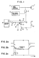
- Fig. 1 is a block diagram of a main part of one embodiment of a retrieval signal recording apparatus suitable for use in magnetic tape recording/reproducing apparatus for video signal.
- This embodiment shows the case in which a cue signal for retrieval is recorded on a magnetic tape by an erase head.
- the erase head is used for recording the cue signal, no additional head is required, and thus the magnetic tape transport mechanism of the conventional recording/reproducing apparatus can be used without any change, that is, it is not necessary for the apparatus to become large-sized.
- a magnetic erase head 1 which is normally used for erasing the whole width of the magnetic tape, and a bias signal generating circuit 2 the output of which is applied to the magnetic head 1 as an erase signal or to an audio signal recording circuit (not shown), as a recording bias signal.
- Shown at 3 is a cue signal generating circuit, which generates a cue signal having a frequency selected so as not to have a small influence on the video and audio signals recorded on the magnetic tape.
- the frequency may be selected to be 30 Hz for the NTSC-system video cassette recorder, and 25 Hz for the PAL-system one.
- the frequency of the cue signal is not necessary to be limited particularly to these values, the use of the values makes it possible to use either the vertical synchronizing signal of the video signal or the rorational position detecting signal from the rotating head unit without a particular oscillator for the signal generating circuit 3, resulting in the circuit arrangement being simple.
- Shown at 5 is a gate circuit for adding the output of this signal generating circuit 3 on the output of the bias signal generating circuit 2, and 4 designates a control circuit which is responsive to a signal from operation means (not shown), to control each circuit of the magnetic tape recording/reproducing apparatus.
- control circuit 4 may be a control circuit which only produces a signal of, for example, "high” level upon recording and a signal of "low” level in the other operation modes, and thus a known control circuit can be used therefor. It is of course possible to use any control circuit which produces distinguishably different signals for the recording mode and the other operation modes, because for example even if the relationship between the "high” and "low” levels of a control circuit and the operation modes is reversed, the output of such a circuit can be used by simply inverting the levels. In this embodiment, it is assumed that in the recording mode the control circuit 4 produces "high" level signal at its output terminal R.
- the output from the terminal R of the control circuit 4 is applied to a gate control circuit, thereby controlling the gate circuit 5.
- the gate circuit 5 is controlled to open, the cue signal from the signal generating circuit 3 is passed therethrough and added on the bias signal from the bias signal generating circuit 2.
- This added signal is applied to the magnetic head 1.
- the gate control circuit can be formed of for example, a monostable multivibration with variable time constant.
- This monostable multivibrator is formed of an AND circuit 13, an invertor 14, a resistor 7, capacitors 8 and 9 and a transistor 10.
- the time constant of the monostable multivibrator can be changed by connecting and disconnecting the capacitor 9 to the time constant circuit. This connecting and disconnecting operation is made by turning on and off the switching transistor 10.
- the capacitance value for determining the time constant is the sum of the capacitances of the capacitors 8 and 9 and thus a large value. If the transistor 10 is turned off, the capacitance value for determining the time constant is only the capacitance of the capacitor 8 and hence a small value.
- the control circuit 4 produces "low” level signal at its output terminal R and thus the potential at one input, or at point A, to the AND circuit 13 is “low” level.
- the capacitor 8 is charged through the resistor 7, thus making the potential of the other input, or point B to the AND circuit 13 be “high” level. Consequently, since the one input and the other input to the AND circuit 13 are "low” and “high” levels, respectively, the output of the AND circuit 13 becomes “low” level. This follows that the gate circuit 5 is closed to prevent the cue signal from being applied to the magnetic head 1.
- a switch 12 is turned on when the magnetic tape is switched to a low tape speed, i.e., if the siwtch 12 which operates in association with the operation of tape speed switching means not shown is provided and is closed when the tape speed is low, a bias voltage is applied through a resistor 11 to the base of the transistor 10. Therefore, the transistor 10 is turned on to connect the capacitor 9 in parallel with the capacitor 8. Consequently, when the control circuit 4 is made in the recording mode, the potential of the other input to the AND circuit 13 is more gradually decreased as shown in Fig. 2b by two-dot chain line because the discharge time constant is increased by the addition of the capacitance of the capacitor 9 to the capacitor 8.
- Fig. 3a shows a recorded state of the magnetic tape in which the cue signal is recorded for a constant time irrespective of change of tape speed.
- the left hand side shows the case of high tape-speed and the right hand side shows the case of low tape-speed.
- the length of the added portion becomes l 1 .
- the length of the added portion is t 2 shorter than l 1 as illustrated unless the recording time of the cue signal is changed.
- the length l 2 becomes 1/3 the length l 1 .
- numeral 103 designates non-recorded portions.
- the length l 1 of the cue signal recorded portion 102a at high tape speed can be made substantially equal to the length l 1 ' of the cue signal recorded portion 102c at low tape speed as shown in Fig. 3b. Therefore, when the tape is travelled at high speed in search mode, even _the cue signal recorded at low tape speed can be surely detected.
- Fig. 4 is a block diagram of another embodiment of this invention.
- the cue signal for retrieval is recorded at both the beginning and the end of the information-signal recorded portion, differing from the previous embodiment in which the cue signal is recorded only at the beginning of that portion.
- the advantage in recording the cue signal at the end of the information recorded portion is that when an information signal is recorded later on the non-recorded portion of the magnetic tape which was partially recorded, the beginning of the non-recorded portion can be rapidly detected easily by - search operation by detecting the cue signal at the end of the previously recorded information signal.
- This embodiment is different from the previous embodiment in the gate control circuit formed of a monostable multivibrator. That is, at the end of the recording mode, a signal is also generated to open the gate circuit 5. Specifically, for example, the inverter 14 in Fig. 1 is removed, and instead of the AND circuit 13 an exclusive OR (hereinafter, abbreviated EXOR) circuit 16 is provided.
- EXOR exclusive OR
- the output of the EXOR circuit 16 becomes “low” level.
- the control circuit 4 produces “low” level output at the end of recording (time t 2 )
- the potential at point A immediately becomes “low” level as shown in Fig. 5a
- the potential at point B gradually decreases to "low” level because the charge of the capacitor 8 discharges through the resistor 7. Consequently, the E XO R circuit 16 produces "high” level output and the "high” level output is kept until the potential at point B becomes lower than the how threshold level Ett.
- the ' high-level signals to open the gate circuit 5 are generated from the EXOR circuit 16 to enable the cue signal for retrieval to be recorded at both the beginning and end of the recording mode as shown in Fig. 5c.
- VHS system video cassette recorder capable of three different tape speeds, i.e., standard, 1/2 standard and 1/3 standard speeds, two-fold and three-fold recording time. If this invention is applied to this apparatus, and if the recording time of the cue signal is selected to be for example, about 1.5 sec for standard tape speed mode, thus 3 sec for 1/2 standard mode and 4.5 sec for 1/3 standard mode, the length of the recorded cue signal for any of the three tape speeds can be made constant. In practice, even if it is not strictly constant, for example, even by the recording time of 2.3 sec for 1/2 standard speed and 3.0 sec for 1/3 standard speed, the recorded cue signal can be detected at high tape speed without trouble.
- a magnetic head used to record the cue signal is preferable to the magnetic head 1 which erases the entire width of the magnetic tape as described previously, a special magnetic head to be made in contact with the entire or a part of the width of the magnetic tape can be provided for recording the cue signal.
- the constants of the time constant circuits are selected so that the length of recorded cue signal has an appropriate value for each recording tape speed and search tape speed.
Landscapes
- Indexing, Searching, Synchronizing, And The Amount Of Synchronization Travel Of Record Carriers (AREA)
- Television Signal Processing For Recording (AREA)
Applications Claiming Priority (2)
| Application Number | Priority Date | Filing Date | Title |
|---|---|---|---|
| JP44118/83 | 1983-03-18 | ||
| JP58044118A JPS59171062A (ja) | 1983-03-18 | 1983-03-18 | 磁気記録再生装置 |
Publications (2)
| Publication Number | Publication Date |
|---|---|
| EP0120420A1 true EP0120420A1 (fr) | 1984-10-03 |
| EP0120420B1 EP0120420B1 (fr) | 1987-09-09 |
Family
ID=12682685
Family Applications (1)
| Application Number | Title | Priority Date | Filing Date |
|---|---|---|---|
| EP84102901A Expired EP0120420B1 (fr) | 1983-03-18 | 1984-03-16 | Dispositif d'enregistrement de signaux de repérage pour un appareil d'enregistrement et de reproduction à bande magnétique |
Country Status (4)
| Country | Link |
|---|---|
| US (1) | US4620239A (fr) |
| EP (1) | EP0120420B1 (fr) |
| JP (1) | JPS59171062A (fr) |
| DE (1) | DE3466113D1 (fr) |
Cited By (2)
| Publication number | Priority date | Publication date | Assignee | Title |
|---|---|---|---|---|
| EP0208536B1 (fr) * | 1985-07-09 | 1993-03-31 | Sony Corporation | Appareil pour enregistrer et/ou reproduire un signal d'information additionnel |
| DE3546768C2 (de) * | 1984-12-25 | 1995-01-26 | Canon Kk | Aufzeichnungsgerät für digitale Informationssignale |
Families Citing this family (6)
| Publication number | Priority date | Publication date | Assignee | Title |
|---|---|---|---|---|
| DE3540462A1 (de) * | 1984-12-25 | 1986-07-03 | Canon K.K., Tokio/Tokyo | Geraet zum aufzeichnen und/oder wiedergeben von informationssignalen |
| JPH0789663B2 (ja) * | 1986-04-15 | 1995-09-27 | キヤノン株式会社 | 情報記録装置 |
| US5202798A (en) * | 1986-04-15 | 1993-04-13 | Canon Kabushiki Kaisha | Still image signal recording apparatus operable by a manually operable member |
| US4724484A (en) * | 1986-08-14 | 1988-02-09 | Ward Richard J | System for testing video equipment |
| JPS6460079A (en) * | 1987-08-31 | 1989-03-07 | Canon Kk | Information signal recorder |
| DE3888126T2 (de) * | 1987-12-14 | 1994-08-18 | Sony Corp | Gerät und Methode zur Aufzeichnung eines digitalen Signals. |
Citations (4)
| Publication number | Priority date | Publication date | Assignee | Title |
|---|---|---|---|---|
| DE2423526A1 (de) * | 1974-05-15 | 1975-11-27 | Licentia Gmbh | Aufzeichnungsgeraet fuer informationen mit markierung bestimmter stellen des aufzeichnungstraegers |
| GB2058431A (en) * | 1979-06-01 | 1981-04-08 | Digital Equipment Corp | Positioning system and formatting scheme for magnetic tape media |
| EP0027617A1 (fr) * | 1979-10-19 | 1981-04-29 | GRUNDIG E.M.V. Elektro-Mechanische Versuchsanstalt Max Grundig | Circuit pour l'enregistrement additionnel de données de commande sur un support d'enregistrement vidéo |
| US4338529A (en) * | 1979-05-09 | 1982-07-06 | Olympus Optical Co., Ltd. | Cue signal generating circuit |
Family Cites Families (3)
| Publication number | Priority date | Publication date | Assignee | Title |
|---|---|---|---|---|
| US3315242A (en) * | 1963-04-24 | 1967-04-18 | Ibm | Modulation and transfer of information achieved by speed differential |
| US3584158A (en) * | 1968-12-10 | 1971-06-08 | Westinghouse Electric Corp | Helium speech unscrambler |
| US3681524A (en) * | 1970-06-16 | 1972-08-01 | Columbia Broadcasting Syst Inc | Multiple frequency time code generator and reader |
-
1983
- 1983-03-18 JP JP58044118A patent/JPS59171062A/ja active Pending
-
1984
- 1984-03-14 US US06/589,645 patent/US4620239A/en not_active Expired - Fee Related
- 1984-03-16 DE DE8484102901T patent/DE3466113D1/de not_active Expired
- 1984-03-16 EP EP84102901A patent/EP0120420B1/fr not_active Expired
Patent Citations (4)
| Publication number | Priority date | Publication date | Assignee | Title |
|---|---|---|---|---|
| DE2423526A1 (de) * | 1974-05-15 | 1975-11-27 | Licentia Gmbh | Aufzeichnungsgeraet fuer informationen mit markierung bestimmter stellen des aufzeichnungstraegers |
| US4338529A (en) * | 1979-05-09 | 1982-07-06 | Olympus Optical Co., Ltd. | Cue signal generating circuit |
| GB2058431A (en) * | 1979-06-01 | 1981-04-08 | Digital Equipment Corp | Positioning system and formatting scheme for magnetic tape media |
| EP0027617A1 (fr) * | 1979-10-19 | 1981-04-29 | GRUNDIG E.M.V. Elektro-Mechanische Versuchsanstalt Max Grundig | Circuit pour l'enregistrement additionnel de données de commande sur un support d'enregistrement vidéo |
Non-Patent Citations (1)
| Title |
|---|
| Patent Abstracts of Japan vol. 5, no. 88, 9 June 1981 & JP-A-56-34175 * |
Cited By (2)
| Publication number | Priority date | Publication date | Assignee | Title |
|---|---|---|---|---|
| DE3546768C2 (de) * | 1984-12-25 | 1995-01-26 | Canon Kk | Aufzeichnungsgerät für digitale Informationssignale |
| EP0208536B1 (fr) * | 1985-07-09 | 1993-03-31 | Sony Corporation | Appareil pour enregistrer et/ou reproduire un signal d'information additionnel |
Also Published As
| Publication number | Publication date |
|---|---|
| DE3466113D1 (en) | 1987-10-15 |
| EP0120420B1 (fr) | 1987-09-09 |
| JPS59171062A (ja) | 1984-09-27 |
| US4620239A (en) | 1986-10-28 |
Similar Documents
| Publication | Publication Date | Title |
|---|---|---|
| US4620239A (en) | Retrieval signal recording apparatus for magnetic tape recording/reproducing apparatus | |
| US4689699A (en) | Information signal recording and/or reproducing apparatus | |
| US4636878A (en) | Combined detector circuit for detecting a tape end or unrecorded area of a tape | |
| US5519549A (en) | VISS circuit for preventing image search malfunction occurring due to variation in speed of video tape | |
| US4626934A (en) | Cue signal recording circuit for magnetic recording and reproducing apparatus | |
| KR920010590A (ko) | 신호 기록 장치 | |
| US4344095A (en) | Recorded-signal position detecting circuit | |
| US4574320A (en) | Dictating machine having a revising function | |
| US5923810A (en) | Index signal recording and reproduction apparatus and method for a recording medium | |
| JPS6228493B2 (fr) | ||
| JPS592210A (ja) | テ−プ種類検出方法 | |
| US4941058A (en) | Data signal recording/reproduction apparatus of a VCR | |
| JP2630776B2 (ja) | ブランク・スキップ機能付vtr | |
| KR900009171B1 (ko) | 고음질 비데오 카세트 레코더(vcr)의 고속 탐색 방법 | |
| KR100220177B1 (ko) | Vcr의 고속탐색시 위치 보정방법 | |
| KR100194037B1 (ko) | 영상신호 처리장치의 테이프 주행속도 검출회로 및 방법 | |
| KR950010611A (ko) | 브이.티.알(vcr)의 기록종료검출 및 녹화방법 | |
| KR940001051Y1 (ko) | 테이프 레코더의 배경음 더빙회로 | |
| KR100257259B1 (ko) | 자기테이프의 정보기록 제어장치와 그 방법 | |
| KR0139196B1 (ko) | 테이프 레코더의 녹음 종료 어드레스 기록 방법 | |
| KR0137863B1 (ko) | 곡선두 탐색 방법 | |
| JP2989416B2 (ja) | 磁気テープ再生装置 | |
| JPS5853004A (ja) | 検索制御方式 | |
| KR950012379A (ko) | 브이씨알의 재생모드 제어방법 | |
| JPH06282898A (ja) | 選曲装置 |
Legal Events
| Date | Code | Title | Description |
|---|---|---|---|
| PUAI | Public reference made under article 153(3) epc to a published international application that has entered the european phase |
Free format text: ORIGINAL CODE: 0009012 |
|
| 17P | Request for examination filed |
Effective date: 19840316 |
|
| AK | Designated contracting states |
Designated state(s): AT DE FR GB IT |
|
| 17Q | First examination report despatched |
Effective date: 19860117 |
|
| GRAA | (expected) grant |
Free format text: ORIGINAL CODE: 0009210 |
|
| AK | Designated contracting states |
Kind code of ref document: B1 Designated state(s): DE GB |
|
| REF | Corresponds to: |
Ref document number: 3466113 Country of ref document: DE Date of ref document: 19871015 |
|
| PLBE | No opposition filed within time limit |
Free format text: ORIGINAL CODE: 0009261 |
|
| STAA | Information on the status of an ep patent application or granted ep patent |
Free format text: STATUS: NO OPPOSITION FILED WITHIN TIME LIMIT |
|
| 26N | No opposition filed | ||
| PGFP | Annual fee paid to national office [announced via postgrant information from national office to epo] |
Ref country code: GB Payment date: 19910307 Year of fee payment: 8 |
|
| PGFP | Annual fee paid to national office [announced via postgrant information from national office to epo] |
Ref country code: DE Payment date: 19910429 Year of fee payment: 8 |
|
| PG25 | Lapsed in a contracting state [announced via postgrant information from national office to epo] |
Ref country code: GB Effective date: 19920316 |
|
| GBPC | Gb: european patent ceased through non-payment of renewal fee | ||
| PG25 | Lapsed in a contracting state [announced via postgrant information from national office to epo] |
Ref country code: DE Effective date: 19921201 |