EP0120436A2 - Procédé et dispositif de commande d'un moteur d'entraînement pour une machine à sonner des cloches - Google Patents
Procédé et dispositif de commande d'un moteur d'entraînement pour une machine à sonner des cloches Download PDFInfo
- Publication number
- EP0120436A2 EP0120436A2 EP84103007A EP84103007A EP0120436A2 EP 0120436 A2 EP0120436 A2 EP 0120436A2 EP 84103007 A EP84103007 A EP 84103007A EP 84103007 A EP84103007 A EP 84103007A EP 0120436 A2 EP0120436 A2 EP 0120436A2
- Authority
- EP
- European Patent Office
- Prior art keywords
- bell
- drive motor
- output signal
- angular velocity
- brake
- Prior art date
- Legal status (The legal status is an assumption and is not a legal conclusion. Google has not performed a legal analysis and makes no representation as to the accuracy of the status listed.)
- Granted
Links
Images

Classifications
-
- G—PHYSICS
- G10—MUSICAL INSTRUMENTS; ACOUSTICS
- G10K—SOUND-PRODUCING DEVICES; METHODS OR DEVICES FOR PROTECTING AGAINST, OR FOR DAMPING, NOISE OR OTHER ACOUSTIC WAVES IN GENERAL; ACOUSTICS NOT OTHERWISE PROVIDED FOR
- G10K1/00—Devices in which sound is produced by striking a resonating body, e.g. bells, chimes or gongs
- G10K1/28—Bells for towers or the like
- G10K1/30—Details or accessories
- G10K1/34—Operating mechanisms
- G10K1/344—Operating mechanisms for an oscillating bell which is driven once per cycle
- G10K1/345—Operating mechanisms for an oscillating bell which is driven once per cycle electrically operated
Definitions
- the invention relates to a method for controlling the drive motor of a bell ringing machine as a function of a specific operating state of the bell, and a device for carrying out the method.
- a pendulum-suspended bell for example a church bell
- an electric motor which is connected to the bell yoke, for example, via a drive chain or V-belt, so that an intonation is generated by striking the clapper.
- the pendulum movement of the bell should slowly rock up from a standstill to a certain amplitude. It is advantageous if this amplitude can be set within wide limits.
- To drive the church bell it is necessary to switch the electric motor on and off at precisely defined points, depending on the direction of vibration of the bell.
- the present invention is the - object of the invention to provide a control of the drive motor of a Glockenläutmaschine of the type mentioned, in which the above-mentioned external influences an optimum in the bell do not matter.
- the object is achieved in that the respective angular velocity of the bell is tapped, that an output signal corresponding to the respective angular velocity is generated and that the starting time and the on duration of the drive motor are controlled via this output signal.
- the switch-on time and the switch-on duration of the drive motor are therefore not determined by a timer, as in the case of the prior art mentioned at the outset, but rather by the speed of the bell itself. From this it follows that the bell can always be knocked in the optimal speed range, this happening almost without jerk and thus without annoying background noises. If the friction of the mechanical system changes due to cold or wear, the optimal time at which the drive motor is to be switched on is shifted, but the optimum speed range for switching on is not. Likewise, the engine only switches off when the bell has reached the correct speed, regardless of how long it takes.
- the output signal corresponding to the respective angular velocity is compared with a target value, and the control signal for the drive motor is derived from this.
- the aforementioned setpoint can expediently be set within certain limits.
- the respective angular velocity of the bell is tapped via a tachometer generator, the respective drive direction of the motor being able to be determined via the polarity of the output signal of the tachometer generator and via the amplitude of the output signal of the tachometer generator the switch-on time and the switch-on duration of the drive motor can be taxed. All the information essential for controlling the drive motor is thus obtained in the simplest way.
- the output signal of the tachometer generator is fed to two integrator stages, the direction of rotation of the bell being determined via one integrator stage and the absolute amount of the angular velocity being determined via the other integrator stage.
- the invention further provides that the eddy current principle is used to brake the bell.
- direct current is expediently passed through the stator winding of the drive motor, this braking current preferably being slowly ramped up during the braking process. This results in a particularly soft braking of the bell.
- drum or disc brakes Another possibility for braking the bell according to the prior art are drum or disc brakes, which, however, have the disadvantage that the bell can come to a standstill in any position, that is to say completely crooked, and thus remains stationary. In addition, a complex and maintenance-intensive mechanism is required.
- a device for carrying out the method for controlling the drive motor of a bell ringing machine as a function of a specific operating state of the bell is characterized according to the invention in that a tachometer generator is provided which taps the angular velocity of the bell and whose output signal controls the operation of the drive motor.
- the tacho generator can preferably interact with the motor shaft of the drive motor and the tacho generator can be integrated in the housing of the drive motor.
- the tachometer generator is connected to a first integration stage with a small time constant and to a second integration stage with a larger time constant, the information about the respective direction of the bell vibration and the information about the second integration stage being communicated via the first integration stage Absolute amount of the respective bell speed (angular speed) is obtained.
- the output of the second integration stage is advantageously connected to two comparison stages, of which one comparison stage is assigned to the forward movement and the other comparison stage is assigned to the rearward movement of the bell, the comparison stages being controlled alternately depending on the direction of rotation of the bell.
- the alternating activation of the two comparison stages is expediently carried out via the signal obtained from the first integration stage.
- the comparison stages can preferably be designed as window discriminators, wherein according to a further advantageous feature of the invention the windows of the window discriminators are adjustable.
- the time constant of the second integrator stage is preferably designed to be adjustable. This makes it very easy to set the switch-on point and the switch-on time of the drive motor and thus the pendulum amplitude and, within certain limits, the frequency.
- an eddy current brake is provided for braking the bell, as a result of which, as described further above, a particularly gentle braking of the bell is achieved.
- a phase gating control is preferably provided which gradually regulates the current passed through the stator winding of the drive motor for braking the bell, which in turn is conducive to the gentle braking of the bell.
- Electronic load relays are preferably provided for switching the drive motor on and off.
- the motor can also be controlled by commercially available motor contactors.
- the electronic load relays have the advantage that they do not require mechanical contacts, which means that they are silent, maintenance-free and wear-free and do not cause radio interference.
- Conventional motor contactors on the other hand, must be additionally suppressed. In the case of the control circuit according to the invention, both alternatives can be used.
- the present invention shows, compared to the known prior art, the advantages of a very wide setting range, precise, low-noise operation, compensation of irregularities in the bell and suspension, avoidance of jerky material stresses, electronics that are maintenance-free compared to mechanical contacts, and soft braking without noise .
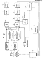
- the bell rotation axis is drivingly connected to a drive motor 1 via a combination of drive chain and steel cable, or via a V-belt or the like.
- the drive motor 1 is a three-phase motor.
- a voltage is derived from the motor shaft 2, which is connected to the bell via the drive, by means of a tachometer generator 3, which voltage depends directly on the angular velocity of the bell.
- the signal voltage of the tachometer generator 3 is now fed to two integrators 4 and 5.
- the second, slow integrator 5 with a larger time constant supplies the amount of the angular velocity.
- This integrator also has the task of compensating for small interferences that are superimposed on the input signal and smoothing the signal.
- the signal of the integrator 5 is then given to two window discriminators F1 and F2, one for "forward” and one for “backward".
- the corresponding discriminator is selected by logic stages 6 and 7 via the signal from integrator 4.
- the logic gives a pulse to the output drivers 8 and 9 and thus switches on the motor 1 via the load relays 10 and 11.
- the switch-on point and switch-on time of the drive motor 1 and thus the pendulum amplitude and, within certain limits, the frequency can be set.
- the window areas F1 and F2 that is to say the response areas of the window discriminators F1 and F2 do not necessarily have to be in the same amplitude ranges. Since the respective window areas can be individually adjusted both with regard to their upper limit and with regard to their lower limit, it is possible to correct irregularities, for example in the bell or in the clapper, by setting the window areas to different amplitude ranges for the forward direction and the backward direction by adjusting the window areas in each case same. ; In this way, for example, a crooked hanging of the bell can be compensated for.
- a one-time, time-adjustable start pulse 13 is given to the motor 1 via the logic stage 14 (OR gate), which deflects the bell pendulum from its rest position.
- the logic stage 14 OR gate
- the control switch 12 When the control switch 12 is turned to its “off” position, the control electronics are automatically switched over to the “braking” operating state.
- the brake 15 is therefore activated.
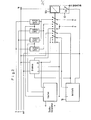
- the motor is first disconnected from the network 16 in all phases, as can be seen, for example, from FIG. 2, in which the control switch 12 is represented by the switch 12a and the motor contactor 12b. Shortly thereafter, a thyristor phase control slowly increases the braking current. In this case, a direct current is sent through the stator winding of the three-phase motor 1, which builds up a magnetic field which brakes the bell very gently, since the braking force also depends on the speed of the bell and thus completely prevents blocking. After the braking process has ended, the power supply unit 16 is automatically switched off.
- FIG. 2 it can also be seen in detail how the three-phase network RST is connected to the motor windings UVW of the three-phase motor 1 and in which way the braking device, the ringing device and the power pack are connected to one another via the control switch 12.
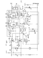
- the ringing circuit is shown in detail in FIG. 4.
- the names of the electronic components listed here refer to data lists from Siemens.
- the time module 20 emits a voltage pulse, the duration of which can be set via the resistor 23 and the capacitor 24, to the logical OR gate 25.
- a driver transistor 26 At the output of the OR gate 25 is a driver transistor 26 which drives the load relay.
- the LEDs 27 and 28 are used for optical control (each for forward or backward movement).
- the voltage signal from the tacho generator runs through the input circuit (series resistor 30, Zener diodes 31 and capacitor 32) into the two integrators 4 and 5.
- Both modules 4 and 5 are inverting integrators in the basic circuit, the time constant of which is via a trimming potentiometer 33 and 34, respectively is adjustable.
- the output signal of the slow integrator 5 is now fed to the two window discriminators F1 and F2.
- the module used here as a window discriminator outputs the logic level H if and only if the input voltage is in an adjustable range (window).
- the "upper edge” and the "lower edge” of the window can be set by two trimming potentiometers 35, 36 and 37, 38, respectively.
- Each of these logic signals is linked to the output signal of the fast integrator 4 by a logical "AND", that is to say that for the direction of movement “forward” the fast integrator stands for “forward” and the voltage of the slow integrator in the area of the window for “ Forward “is to turn on the motor.
- this function is implemented by a “NAND” 39 or 40 with four inputs and an inverter 41 or 42.
- the two additional ones Inputs of blocks 39 and 40 are used to mutually lock the running directions and for overall locking when braking.
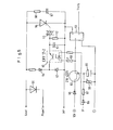
- the brake circuit according to FIG. 5 is described below.
- the control switch connects the control line St to ground, the brake begins to act.
- the optocoupler 50 slowly increases the charging current of the capacitor 51.
- the DIAC 53 reaches its ignition voltage, it becomes conductive thyristor 54 and the direct current can flow into the motor (phase control).
- the motor current flows via a freewheeling diode 55, which brings about a smoothing of the current profile and an increase in the braking effect.
- the noise level is also reduced.
- Resistor 56 and capacitor 57 in parallel with the thyristor cause further interference suppression.
- the current through the optocoupler and thus the braking current can be adjusted via a trimmer 58.
- the duration of the braking is determined by the adjustable resistor 59 and the capacitor 60.
- the capacitor 60 charges up via the resistor 61.
- the field effect transistor 62 thus controls and switches on the voltage supply via the load relay 63.
Landscapes
- Physics & Mathematics (AREA)
- Engineering & Computer Science (AREA)
- Acoustics & Sound (AREA)
- Multimedia (AREA)
- Control Of Electric Motors In General (AREA)
- Stopping Of Electric Motors (AREA)
Priority Applications (1)
| Application Number | Priority Date | Filing Date | Title |
|---|---|---|---|
| AT84103007T ATE37751T1 (de) | 1983-03-23 | 1984-03-19 | Verfahren zum steuern des antriebsmotors einer glockenlaeutmaschine sowie vorrichtung zur durchfuehrung des verfahrens. |
Applications Claiming Priority (2)
| Application Number | Priority Date | Filing Date | Title |
|---|---|---|---|
| DE3310567A DE3310567C2 (de) | 1983-03-23 | 1983-03-23 | Verfahren zum Steuern des Antriebsmotors einer Glockenläutmaschine sowie Vorrichtung zur Durchführung des Verfahrens |
| DE3310567 | 1983-03-23 |
Publications (3)
| Publication Number | Publication Date |
|---|---|
| EP0120436A2 true EP0120436A2 (fr) | 1984-10-03 |
| EP0120436A3 EP0120436A3 (en) | 1986-03-26 |
| EP0120436B1 EP0120436B1 (fr) | 1988-10-05 |
Family
ID=6194422
Family Applications (1)
| Application Number | Title | Priority Date | Filing Date |
|---|---|---|---|
| EP84103007A Expired EP0120436B1 (fr) | 1983-03-23 | 1984-03-19 | Procédé et dispositif de commande d'un moteur d'entraînement pour une machine à sonner des cloches |
Country Status (3)
| Country | Link |
|---|---|
| EP (1) | EP0120436B1 (fr) |
| AT (1) | ATE37751T1 (fr) |
| DE (1) | DE3310567C2 (fr) |
Cited By (6)
| Publication number | Priority date | Publication date | Assignee | Title |
|---|---|---|---|---|
| EP0191889A3 (en) * | 1985-02-14 | 1987-11-11 | Herforder Elektricitats-Werke Bokelmann & Kuhlo Gmbh & Co. | Bell-ringing engine |
| EP0486453A1 (fr) * | 1990-11-12 | 1992-05-20 | N.V. Clock O Matic | Procédé et dispositif pour faire sonner une cloche |
| EP1094443A1 (fr) * | 1999-10-20 | 2001-04-25 | Joh. Muff AG | Méthode de contrôle de l'angle d'oscillation d'une cloche d'église |
| EP1310941A1 (fr) * | 2001-11-09 | 2003-05-14 | Clock-O-Matic N.V. | Une méthode et un dispositif pour contrôler l'angle d'oscillation de pendule d'une cloche |
| US7735759B2 (en) | 2006-08-03 | 2010-06-15 | Elringklinger Ag | Method for the production of a flowable powder of a fluoropolymer compound and flowable powder produced according to the method |
| CN116184191A (zh) * | 2022-12-23 | 2023-05-30 | 深圳市爱图仕影像器材有限公司 | 步进电机的堵转检测方法及装置 |
Families Citing this family (5)
| Publication number | Priority date | Publication date | Assignee | Title |
|---|---|---|---|---|
| DE3714465C3 (de) * | 1987-04-30 | 1995-06-29 | Philipp Hoerz Gmbh & Co Kg | Verfahren zum Steuern des Antriebsmotors einer Glockenläutemaschine und Vorrichtung zur Durchführung des Verfahrens |
| DD274701B1 (de) * | 1988-08-09 | 1991-02-21 | Rainer Haberstroh | Elektrischer glockenlaeuteantrieb |
| FR2697387B1 (fr) * | 1992-10-28 | 1994-12-16 | Pierre Bodet | Dispositif destiné à entretenir un mouvement alternatif ou pendulaire. |
| DE19522286C2 (de) * | 1995-06-20 | 1999-04-15 | Woelfel Horst Prof Dr Ing | Läuteantrieb für eine Glocke |
| EP2551844B1 (fr) * | 2011-07-28 | 2014-05-07 | Muff Kirchturmtechnik AG | Procédé de réglage d'un angle de déviation d'une cloche et dispositif d'entraînement pour le fonctionnement réglé d'une cloche couplée au dispositif d'entraînement |
Family Cites Families (4)
| Publication number | Priority date | Publication date | Assignee | Title |
|---|---|---|---|---|
| FR374661A (fr) * | 1906-09-26 | 1907-06-20 | Hermann Ruetschi | Cloche avec dispositif électromagnétique de freinage du battant |
| FR917485A (fr) * | 1944-11-28 | 1947-01-08 | Asea Ab | Perfectionnements aux sonneries électriques de cloches |
| US2952013A (en) * | 1955-08-19 | 1960-09-06 | Josef Pfundner | Bell ringing machines |
| GB1017459A (en) * | 1963-03-22 | 1966-01-19 | Ampex | Improvements in or relating to motor drive circuits |
-
1983
- 1983-03-23 DE DE3310567A patent/DE3310567C2/de not_active Expired
-
1984
- 1984-03-19 AT AT84103007T patent/ATE37751T1/de not_active IP Right Cessation
- 1984-03-19 EP EP84103007A patent/EP0120436B1/fr not_active Expired
Cited By (6)
| Publication number | Priority date | Publication date | Assignee | Title |
|---|---|---|---|---|
| EP0191889A3 (en) * | 1985-02-14 | 1987-11-11 | Herforder Elektricitats-Werke Bokelmann & Kuhlo Gmbh & Co. | Bell-ringing engine |
| EP0486453A1 (fr) * | 1990-11-12 | 1992-05-20 | N.V. Clock O Matic | Procédé et dispositif pour faire sonner une cloche |
| EP1094443A1 (fr) * | 1999-10-20 | 2001-04-25 | Joh. Muff AG | Méthode de contrôle de l'angle d'oscillation d'une cloche d'église |
| EP1310941A1 (fr) * | 2001-11-09 | 2003-05-14 | Clock-O-Matic N.V. | Une méthode et un dispositif pour contrôler l'angle d'oscillation de pendule d'une cloche |
| US7735759B2 (en) | 2006-08-03 | 2010-06-15 | Elringklinger Ag | Method for the production of a flowable powder of a fluoropolymer compound and flowable powder produced according to the method |
| CN116184191A (zh) * | 2022-12-23 | 2023-05-30 | 深圳市爱图仕影像器材有限公司 | 步进电机的堵转检测方法及装置 |
Also Published As
| Publication number | Publication date |
|---|---|
| DE3310567C2 (de) | 1985-12-12 |
| ATE37751T1 (de) | 1988-10-15 |
| EP0120436B1 (fr) | 1988-10-05 |
| EP0120436A3 (en) | 1986-03-26 |
| DE3310567A1 (de) | 1984-10-04 |
Similar Documents
| Publication | Publication Date | Title |
|---|---|---|
| DE19919374B4 (de) | Mit variabler Kraft unterstützende Servolenkungsvorrichtung | |
| EP0120436B1 (fr) | Procédé et dispositif de commande d'un moteur d'entraînement pour une machine à sonner des cloches | |
| DE19733581C1 (de) | Verfahren zur Erkennung der Position und der Bewegungsrichtung eines bewegbar gelagerten Teils an einem elektrischen Motor | |
| EP0014241B1 (fr) | Procédé pour l'asservissement d'un mécanisme à moteur à courant continu vers un point de destination et un circuit pour la mise en oeuvre de ce procédé | |
| DE2742054A1 (de) | Schutzvorrichtung fuer die vorschubeinrichtung einer maschinenanlage mit gleichstrommotor | |
| EP1133612A1 (fr) | Procede permettant de limiter la force de fermeture de parties mobiles | |
| DE19639974A1 (de) | Kontroller zum Umsetzen von manuellem auf automatischen Betrieb einer Fahrzeugtür, die zwischen einer geöffneten und geschlossenen Position beweglich ist | |
| DE2102583C3 (de) | Aufzug-Steuerschaltung | |
| DE102015106428A1 (de) | Schaltkreis zum Bestimmen einer Position eines Bewegungselements | |
| DE19539577B4 (de) | Verfahren zum Überwachen des Bewegungswegs eines Teils | |
| DE19527456B4 (de) | Verfahren zum Positionieren eines Teils | |
| DE69219392T2 (de) | Steuerungsanordnung für einen Motor, insbesondere für den Antrieb von Aufzugstüren | |
| DE3209394A1 (de) | Kollektorloser gleichstrommotor | |
| DE1942667B2 (de) | Verfahren zur Lastregelung von Schiffsmotoren und Anordnung zur Durchführung des Verfahrens | |
| DE3402468C2 (de) | Steuervorrichtung zur Steuerung der Geschwindigkeit einer Antriebseinrichtung einer Nähmaschine | |
| DE2731706A1 (de) | Steuerschaltung | |
| EP0666957A1 (fr) | Entrainement electromoteur | |
| DE102015106429A1 (de) | Steuervorrichtung für einen Fahrzeugsitz | |
| DE1806700A1 (de) | Geschwindigkeitssteuereinrichtung | |
| DE3441451A1 (de) | Steuerschaltung fuer einen schrittmotor | |
| DE3344665C2 (de) | Geschwindigkeits-Begrenzungseinrichtung für ein Kraftfahrzeug | |
| DE102009019183B4 (de) | Interpolationsverfahren zur Überbrückung der Freilaufphase eines Stellvorgangs | |
| DE2945587A1 (de) | Steuereinrichtung fuer eine numerisch gesteuerte einrichtung, z.b. eine werkzeugmaschine | |
| DE2345711A1 (de) | Verfahren und einrichtung zur beseitigung des einflusses von spiel auf den antrieb der achsen von werkzeugmaschinen | |
| DE69308348T2 (de) | Verfahren zur Regelung eines Motors mit niedriger Geschwindigkeit |
Legal Events
| Date | Code | Title | Description |
|---|---|---|---|
| PUAI | Public reference made under article 153(3) epc to a published international application that has entered the european phase |
Free format text: ORIGINAL CODE: 0009012 |
|
| AK | Designated contracting states |
Designated state(s): AT BE CH FR LI LU |
|
| RAP1 | Party data changed (applicant data changed or rights of an application transferred) |
Owner name: SALOMON, PAUL |
|
| PUAL | Search report despatched |
Free format text: ORIGINAL CODE: 0009013 |
|
| AK | Designated contracting states |
Kind code of ref document: A3 Designated state(s): AT BE CH FR LI LU |
|
| 17P | Request for examination filed |
Effective date: 19860905 |
|
| 17Q | First examination report despatched |
Effective date: 19880201 |
|
| RAP3 | Party data changed (applicant data changed or rights of an application transferred) |
Owner name: SALOMON, PAUL |
|
| GRAA | (expected) grant |
Free format text: ORIGINAL CODE: 0009210 |
|
| AK | Designated contracting states |
Kind code of ref document: B1 Designated state(s): AT BE CH FR LI LU |
|
| REF | Corresponds to: |
Ref document number: 37751 Country of ref document: AT Date of ref document: 19881015 Kind code of ref document: T |
|
| ET | Fr: translation filed | ||
| PG25 | Lapsed in a contracting state [announced via postgrant information from national office to epo] |
Ref country code: LU Free format text: LAPSE BECAUSE OF NON-PAYMENT OF DUE FEES Effective date: 19890331 |
|
| PLBE | No opposition filed within time limit |
Free format text: ORIGINAL CODE: 0009261 |
|
| STAA | Information on the status of an ep patent application or granted ep patent |
Free format text: STATUS: NO OPPOSITION FILED WITHIN TIME LIMIT |
|
| 26N | No opposition filed | ||
| REG | Reference to a national code |
Ref country code: CH Ref legal event code: PUE Owner name: RUDOLF PERNER GMBH & CO. GLOCKENGIESSEREI |
|
| REG | Reference to a national code |
Ref country code: FR Ref legal event code: TP |
|
| BECA | Be: change of holder's address |
Free format text: 940120 *RUDOLF PERNER G.M.B.H. & CO GLOCHENGIESSEREI:STEPHANSTRASSE 18/20, 94034 PASSAU |
|
| PGFP | Annual fee paid to national office [announced via postgrant information from national office to epo] |
Ref country code: CH Payment date: 19970226 Year of fee payment: 14 |
|
| PGFP | Annual fee paid to national office [announced via postgrant information from national office to epo] |
Ref country code: FR Payment date: 19970228 Year of fee payment: 14 |
|
| PGFP | Annual fee paid to national office [announced via postgrant information from national office to epo] |
Ref country code: AT Payment date: 19970327 Year of fee payment: 14 |
|
| PG25 | Lapsed in a contracting state [announced via postgrant information from national office to epo] |
Ref country code: AT Free format text: LAPSE BECAUSE OF NON-PAYMENT OF DUE FEES Effective date: 19980319 |
|
| PG25 | Lapsed in a contracting state [announced via postgrant information from national office to epo] |
Ref country code: LI Free format text: LAPSE BECAUSE OF NON-PAYMENT OF DUE FEES Effective date: 19980331 Ref country code: FR Free format text: THE PATENT HAS BEEN ANNULLED BY A DECISION OF A NATIONAL AUTHORITY Effective date: 19980331 Ref country code: CH Free format text: LAPSE BECAUSE OF NON-PAYMENT OF DUE FEES Effective date: 19980331 |
|
| REG | Reference to a national code |
Ref country code: CH Ref legal event code: PL |
|
| REG | Reference to a national code |
Ref country code: FR Ref legal event code: ST |
|
| PGFP | Annual fee paid to national office [announced via postgrant information from national office to epo] |
Ref country code: BE Payment date: 20030424 Year of fee payment: 20 |
|
| BE20 | Be: patent expired |
Owner name: *RUDOLF PERNER G.M.B.H. & CO GLOCHENGIESSEREI Effective date: 20040319 |