EP0120442A1 - Dispositif pour régler l'inclinaison de l'axe optique des phares d'un véhicule - Google Patents
Dispositif pour régler l'inclinaison de l'axe optique des phares d'un véhicule Download PDFInfo
- Publication number
- EP0120442A1 EP0120442A1 EP84103050A EP84103050A EP0120442A1 EP 0120442 A1 EP0120442 A1 EP 0120442A1 EP 84103050 A EP84103050 A EP 84103050A EP 84103050 A EP84103050 A EP 84103050A EP 0120442 A1 EP0120442 A1 EP 0120442A1
- Authority
- EP
- European Patent Office
- Prior art keywords
- adjusting
- sleeve
- adjusting rod
- light axis
- inclination
- Prior art date
- Legal status (The legal status is an assumption and is not a legal conclusion. Google has not performed a legal analysis and makes no representation as to the accuracy of the status listed.)
- Granted
Links
- 230000007246 mechanism Effects 0.000 claims abstract description 18
- 230000009467 reduction Effects 0.000 claims abstract description 6
- 238000003780 insertion Methods 0.000 claims description 14
- 230000037431 insertion Effects 0.000 claims description 14
- 238000012856 packing Methods 0.000 description 7
- 230000008859 change Effects 0.000 description 6
- 238000010276 construction Methods 0.000 description 2
- 238000010586 diagram Methods 0.000 description 2
- 229920003002 synthetic resin Polymers 0.000 description 2
- 239000000057 synthetic resin Substances 0.000 description 2
- 230000009471 action Effects 0.000 description 1
- 238000001514 detection method Methods 0.000 description 1
- 238000012986 modification Methods 0.000 description 1
- 230000004048 modification Effects 0.000 description 1
- 239000000725 suspension Substances 0.000 description 1
Images






Classifications
-
- B—PERFORMING OPERATIONS; TRANSPORTING
- B60—VEHICLES IN GENERAL
- B60Q—ARRANGEMENT OF SIGNALLING OR LIGHTING DEVICES, THE MOUNTING OR SUPPORTING THEREOF OR CIRCUITS THEREFOR, FOR VEHICLES IN GENERAL
- B60Q1/00—Arrangement of optical signalling or lighting devices, the mounting or supporting thereof or circuits therefor
- B60Q1/02—Arrangement of optical signalling or lighting devices, the mounting or supporting thereof or circuits therefor the devices being primarily intended to illuminate the way ahead or to illuminate other areas of way or environments
- B60Q1/04—Arrangement of optical signalling or lighting devices, the mounting or supporting thereof or circuits therefor the devices being primarily intended to illuminate the way ahead or to illuminate other areas of way or environments the devices being headlights
- B60Q1/06—Arrangement of optical signalling or lighting devices, the mounting or supporting thereof or circuits therefor the devices being primarily intended to illuminate the way ahead or to illuminate other areas of way or environments the devices being headlights adjustable, e.g. remotely-controlled from inside vehicle
- B60Q1/076—Arrangement of optical signalling or lighting devices, the mounting or supporting thereof or circuits therefor the devices being primarily intended to illuminate the way ahead or to illuminate other areas of way or environments the devices being headlights adjustable, e.g. remotely-controlled from inside vehicle by electrical means including means to transmit the movements, e.g. shafts or joints
-
- B—PERFORMING OPERATIONS; TRANSPORTING
- B60—VEHICLES IN GENERAL
- B60Q—ARRANGEMENT OF SIGNALLING OR LIGHTING DEVICES, THE MOUNTING OR SUPPORTING THEREOF OR CIRCUITS THEREFOR, FOR VEHICLES IN GENERAL
- B60Q2200/00—Special features or arrangements of vehicle headlamps
- B60Q2200/30—Special arrangements for adjusting headlamps, e.g. means for transmitting the movements for adjusting the lamps
- B60Q2200/32—Ball-joints
Definitions
- the present invention relates to a device for adjusting the inclination of the light axis of headlamps of a motor vehicle.
- the headlamps of a motor vehicle or car are needed to light ahead the car in such a way that the driver can drive the car withou hindrance and that those who drive cars coming up cannot be dazzled by the light.
- the headlamps attached to the car in the course of car assembly are therefore aiming-adjusted to exactly direct their light axis so as to achieve easy driving but not to dazzle the drivers who operate cars coming up.
- the light axis of the headlamps change, however, depending upon the carrying conditions such as number of persons boarded and weight of cargo loaded. Namely, they are shifted upward when a heavy cargo is loaded on the back of the car but downward when it is loaded on the front of the car..
- the conventional headlamp for motor vehicles is provided with the device for levelling the headlamp so as to adjust (or correct) the inclination of the light axis of said headlamp to return to its aimed position, counterbalancing various changes of car condition.
- the headlamp levelling means is independednt of the aiming means.
- the aiming means must be connected to the device for adjusting the inclination of the light axis of headlamp means of a different connector, thereby increasing the number of parts used and making their attachment to the headlamp complicated and the space which they occupy large.
- the conventional devices for adjusting the inclination of the light axis of headlamp are grouped in construction to the type wherein the light axis is changed according to the amount of linear movement of a shaft driven by a motor and wherein the angle of the headlamp is detected by the operation of a switch which serves to detect the moved position of the shaft; and to the other type wherein both of a motor and a wire are used in such a way that the crank-connected wire is tensioned by the motor to change the angle of the headlamp in upward and downward directions.
- the present invention is therefore intended to eliminate the above-mentioned drawbacks.
- An object of the present invention is to provide a device for adjusting the inclination of the light axis of a headlamp for motor vehicles, and which device is compact and can be formed as a unit and easily attached to the headlamp or car.
- Another object of the present invention is to provide a device for adjusting the inclination of the light axis of a headlamp for motor vehicles, and which device is compact, small in the number of parts used, and enables the headlamp to be easily attached to the car body, occupying the smallest space.
- a further object of the present invention is to provide a device for adjusting the inclination of the light axis of a headlamp for motor vehicles, and which device is provided with aiming and levelling mechanisms of headlamps.
- a still further obfect of the present invention it to provide a device for adjusting the inclination of the light axis of a headlamp for motor vehicles, and which device is compact and enables the amount of movement of a shaft for changing the inclination angle of the headlamp to be achieved with high accuracy.
- a still further object of the present invention is to provide a device for adjusting the inclination of the light axis of a headlamp for motor vehicles wherein the amount of movement of a drive shaft member for adjusting the inclination angle of the headlamp is detected by a continuous variable resistor to adjust the inclination of the light axis with high accuracy, and which device can be small-sized as a whole.
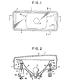
- Fig. 1 shows a headlamp for motor vehicles to which a first example of a device for adjusting the inclination of the light axis of headlamps according to the present invention is attached.
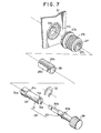
- reference numeral 1 represents a headlamp of the so-called reflector movable type, which comprises a lens 2 arranged at the front of a lamp housing 3, and a reflector 4 supported by the lamp housing 3, as shown in Figs.2 and 3.
- Numeral 5 denotes a bulb attached to the reflector 4, and 6 a rubber cover fitted onto the backside opening of the lamp housing 3.
- a base 5a of the bulb 5 is closely fitted into the water- and dust-proof rubber cover 6 and projected outside the lamp housing 3.
- the reflector 4 is supported swingable by the lamp housing 3 at three points, one of which is a fulcrum mechanism 7.
- the other of the remaining two points is an aiming means 10, and the last is a light axis adjusting device 20 provided with aiming and levelling mechanisms and attached to the lamp housing 3 via a bracket 15.
- the fulcrum mechanism 7 is a ball joint comprising snap-engaging a pivot rod 8 fixed to an attachment piece 4a at the backside of the reflector 4 with a pivot holder 9 attached to the lamp housing 3.
- Figs. 1 is a ball joint comprising snap-engaging a pivot rod 8 fixed to an attachment piece 4a at the backside of the reflector 4 with a pivot holder 9 attached to the lamp housing 3.
- the aiming means 10 includes a rotatable adjusting screw 11 which passes through the lamp housing 3 and which is limited in its movement toward its axial direction, a screw mounting 48 made of synthetic resin and having a pair of elastic engagement pieces 46 and 46 at the foremost end thereof and a through-hole 47 formed therein, and a ball joint 50 fitted into the through-hole 47 of the screw mounting 48 and having a through-hole 49 provided with a screw-thread into which a screw-threaded portion 11A of the adjusting screw 11 is screwed.
- the elastic engagement pieces 46 of the screw mounting 48 are forced into an opening 51 of an attachment piece 4b at the backside of the reflector 4, in such a way that the attachment piece 4b is engaged with grooves formed at the base 46A of the engagement pieces 46, thereby holding the screw mounting 48 non-rotatable relative to the attachment piece 4 b thanks to the elasticity of the engagement pieces 46.
- the ball joint 50 is fitted into the through-hole 47 of the screw mounting 48 in such a way that the ball joint 50 does not rotate around the axis of the screw mounting 48, and the screw-threaded portion 11A of the adjusting screw 11 is screwed into the through-hole 49 of the ball joint 50.
- the rotation of the ball joint 50 around the axis of the screw mounting 48 is prevented by engaging projections 52 and 52 on the outer circumference of the ball joint 50 with slits 53 of the screw mounting 48.
- the reflector 4 can be swung in left and right directions in Fig. 1 and'also be swung- to smoothly schieve an arc movement which is perpendicular to the arc movement attained when the reflector 4 is swung in left and right directions in Fig. 1.
- reference numeral 11B represents a collar of the adjusting screw 11, which can be held rotatable at its predetermined position by attaching the collar 11B, a water-proof seal packing 13 and a holder 14 to the lamp housing 3 in this order.
- light axis adjusting device 20 As apparent from the example of light axis adjusting device 20 shown in Figs. 4 through 8, it comprises a motor 23, a hollow gear 27 rotatable at its predetermined position through a speed reducing mechanism 24 which reduces the rotation speed of the motor 23, a sleeve 28 screwed into the hollow gear 27 and movable linearly in relation to the hollow gear 27, a drive shaft member 29 fitted into the sleeve 28 to adjust the light axis of the headlamp 1, using the linear movement of the sleeve 28, and a continuous variable resistor 34 made operative by the rotation of the hollow gear 27, wherein the rotation of the motor 23 can be stopped at a predetermined position by detecting a difference in voltage, using the continuous variable resistor 34.
- the motor 23 is arranged in a chamber formed by two casings 21 and 22.
- the speed reduction mechanism 24 includes a worm gear 25 attached to the rotating shaft of the motor 23, and a wheel gear 26 engaged with the worm gear 25.
- the wheel gear 26 has a first gear portion 26a engaged with the worm gear 25 and a second gear portion 26b, smaller in diameter than the first gear portion 26a.
- the wheel gear 26 is supported rotatable by the casing 21. As shown in Fig.
- the hollow gear 27 has a first flange-like gear portion 27a formed thereon adjacent to one end thereof and engageable with the second gear portion 26b of the wheel gear 26, a screw thread 27b formed on the inner circumference thereof, and a second gear portion 27c formed on the outer circumference thereof and smaller in diameter than the first gear portion 27a.
- One end of the hollow gear 27 is fitted into a recess 21b formed around a through-hole 21a in the casing 21, while the other end thereof is contacted with the casing 22, so that the hollow gear 27 can be supported rotatable at a predetermined position between the casings 21 and 22.
- the sleeve 28 is formed non-circular in section, as shown in Fig. 7.
- a flat surface 28a is formed on the outer circumference and along the longitudinal axis of the sleeve 28 to make its section non-circular like D-shape.
- Formed on the remaining outer circumference of the sleeve 28 is a screw thread 28b engageable with the screw thread 27b of the hollow gear 27.
- the sleeve 28 thus arranged is supported non-rotatable by screwing it into the hollow gear 27 while fitting its remaining end into the through-hole 21a of the casing 21. More specifically, the through-hole 21a of the casing 21 is formed to have a non-circular D-like section which corresponds to the external form of the sleeve 28.
- the drive shaft member 29 fitted into the sleeve 28 to adjust the light axis of the headlamp 1 responsive to the linear movement of the sleeve 28 includes a shaft portion 30 and an adjusting rod 31, as shown in Fig. 7.
- the shaft portion 30 has a collar 30a formed at the central portion thereof, and an insertion 30b formed, rectangular in section, for example, on one side thereof.
- the adjusting rod 31 has a spherical socket portion 31b formed at-one end thereof and provided with a slit 31a, and a step 31c formed on the outer circumference and adjacent to the one end thereof.
- the adjusting rod 31 has a rectangular hole 31d which is formed at the other end thereof and which corresponds to the external form of the insertion 30b of the shaft portion 30, and a groove 3le formed on the outer circumference and adjacent to the other end thereof.
- a smaller-diameter portion 31f of the adjusting rod 31 is inserted into the sleeve 28 till its step 31c strikes on one end face of the sleeve 28, and an E-ring 32 is then fitted into the groove 3le on its foremost end projected from the sleeve 28, which is thus prevented from moving in its thrusting direction but held freely rotatable.
- the insertion 30b and the hole 31d may be formed non-circular elliptic in section, and may also be formed reversely, the insertion formed on the adjusting rod while the hole formed in the shaft portion.
- the insertion 30b of the shaft portion 30 is inserted into the hole 31d of the adjusting rod 31 to thereby form the drive shaft member 29, and the shaft portion 30 is supported, rotatable at a predetermined position, by the holder 37 through the water-proof packing 36, said holder 37 being fixed to the casing 22 by means of screws.
- a ball portion 16a formed at one end of a connector rod 16 which passes through the lamp housing 3 and which is.allowed to rotate there is fitted into the spherical socket portion 31b of the adjusting rod 31, with its projections 16b received in the slit 31a of the spherical socket portion 31b.
- the connector rod 16 has a screw-thread portion 16c, opposite to its ball portion 16a, and the screw-thread portion 16c of the connector rod 16 is screwed into a through-hole 149 of a ball joint 150, which is formed spherical and provided with projections 152 and 152 which are shifted by about 180° from each other-on the ball joint 150.
- the ball joint 150 is held freely swingable by a connector rod holding mounting 148 fixed to the attachment piece 4c on the backside of the reflector 4. More specifically, the mounting 148 is made of synthetic resin, and has a pair of elastic engagement pieces 146 and 146 on its foremost end.
- the mounting 148 also has a through-hole 147 which is made spherical, corresponding to the external form of the ball joint 150, and slits 153 and 153 into which the projections 152 and 152 of the ball joint 150 are fitted.
- a through-hole 147 which is made spherical, corresponding to the external form of the ball joint 150, and slits 153 and 153 into which the projections 152 and 152 of the ball joint 150 are fitted.
- the elastic engagement pieces 146 and 146 of the mounting 148 are forced into an opening 151 of the attachment piece 4c to engage the piece 4c with a groove 146A which is provided at the base of each of the engagement pieces 146, so that the mounting 148 can be engaged, non-rotatable, with the attachment piece 4c due to the elasticity of the engagement pieces 146.
- reference numeral 17 denotes a water-proof seal packing, 18 a holder for attaching the seal packing 17 to the lamp housing 3, 38 a knob arranged on the other end of the shaft,30, and 54 screws for attaching the holder 18 to the lamp housing 3.
- aiming adjustment which is to be done at the time of attaching the headlamps 1 to the car body can be achieved: the shaft 30 is hand-operated; the adjusting rod 31 is rotated in the sleeve 28 but together with the shaft 30; the connector rod 16 connected to the adjusting rod 31 is also rotated; the ball joint 150 into which the connector rod 16 is screwed is thus moved linearly together with the mounting 148 and the reflector 4 is thus swung to determine an initial direction of the light axis.
- Levelling adjustment which serves to correspond to any directional change of the light axis caused depending upon the carrying conditions can be achieved by rotating the hollow gear 27 by means of the motor 23 and the speed reduction mechanism 24.
- the sleeve 28 is linearly moved but not rotated while the adjusting rod 31 is also linearly moved together with the sleeve 28, sliding on the insertion 30b of the shaft 30.
- the connector rod 16 connected to the adjusting rod 31 is thus linearly moved to swing the reflector 4, thereby enabling the light axis to return to its original position aimed.
- the continuous variable resistor 34 for controlling and stopping the rotation of the motor 23 is of rotary volume in this embodiment, and this resistor 34 is attached to the casing 21, as shown in Fig. 5.
- Fixed to the shaft of the resistor 34 is a worm wheel 33, which is engaged with the second . gear portion 27c of the hollow gear 27 to reduce the rotation.speed of the resistor 34.
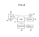
- Fig. 8 is a control block diagram, in which numeral 39 represents a switch, 40 a reference voltage regulator, 41 a voltage comparison circuit and 42 a driver circuit. In order to adjust the light axis of the headlamp 1 which is arranged as shown in Fig.
- the levelling adjustment is carried out as follows: the switch 39 accessible from the driver's seat is operated to determine a voltage which corresponds to a light axis adjusting angle needed to return the headlamp 1 to its original position; this voltage is compared with the voltage of the continuous variable resistor 34 by means of the voltage comparison circuit 41; when they are different from each other, the motor 23 is rotated by the driver circuit 42; the hollow gear 27 is thus rotated to make the continuous variable resistor 34 operative, and the motor 23 is stopped at that position of the continuous variable resistor 34 whose voltage becomes equal to the predetermined voltage; the adjusting rod 31 of the driver shaft member 29 is linearly moved together with the sleeve 28 because the latter is driven by the rotation of the hollow gear 27; and the reflector 4 is swung and return to its original position, responding to the above-described linear movement of the connector rod 16, thereby enabling the light axis of the headlamp 1 to be directed in its optimum direction.
- the light axis adjusting device 20 uses the single.continuous variable resistor 34 to achieve detection function, thereby enabling the device 20 itself to be made small-sized.
- the continuous variable resistor 34 can change voltage continuously, it is easy to determine that position .of the resistor 34 where the voltage of the resistor 34 becomes equal to the predetermined voltage, thereby enabling the positional accuracy of the stopped resistor 34 to be remarkably enhanced.
- the strength of suspension becomes different even under same carrying conditions, depending upon the kinds of motor vehicles, and the amount of light axis adjustment must be therefore changed to correspond to this change.
- this change can be covered only by changing the predetermined voltage in the car. This teaches us that the light axis adjusting device 20 can be applied to any kind of motor vehicles. Further, the light axis adjusting device 20 also has the aiming function, thereby making it easy to attach the device 20 to the car body or headlamps.
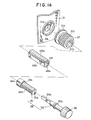
- Figs. 13 and 14 show a second example of light axis adjusting device according to the present invention. Parts same as those in the first embodiment will be denoted by same reference numerals and description on these parts will be omitted.
- an adjusting rod 131 of the driver shaft member 29 has a spherical socket portion 131b (see Fig. 13) formed at one end thereof and provided with a slit 131a, a step 131c formed on the outer circumference adjacent to the one end thereof, and a screw thread 131f formed extending from the step 131c to the other end thereof.
- a sleeve 128 which is formed non-circular because of that surface 128a formed on its outer circumference has an inner screw thread 128c engageable with the screw thread 131f of the adjusting rod 131. As shown in Fig.
- the adjusting rod 131 of the driver shaft member 29 is screwed into the sleeve 128 and a ball portion 19a of a connector rod 19 is pivot-fitted into the spherical socket portion 131b.
- Projections 19b of the ball portion 19a is received into the slits 131a and 131a a second ball joint 19c formed on the other end of the connector rod 19 is snapped into a rod mounting 43 arranged in the attachment piece 4c of the reflector 4.
- the shaft 30 of the driver shaft member 29 arranged at the casing 22 is rotated at a certain position to rotate but linearly move only the adjusting rod 131 because the sleeve 128 is locked by the casing 21, so that the connector rod 19 can be thus rotated but linearly moved to swing the reflector 4 so as to adjust the light axis of the headlamp l.
- the sleeve 128 is rotated but linearly moved by the hollow gear 27 rotated by the motor 23, so that the adjusting rod 131 engaged with the sleeve 128 can be thus linearly moved to swing the reflector 4 through the connector rod 19 so as to return the light axis of the reflector to its predetermined position.
- Figs. 15-and 16 are sectional and perspective views, respectively, showing a third embodiment of the present invention. Also in this case, parts same as those in the above-described embodiments will be represented by same reference numerals and description on these parts will be omitted.
- a driver shaft member 129 is a parts comprising the shaft portion and the driver portion, as shown in Fig. 16.
- the driver shaft member 129 has a spherical socket portion 129b (see Fig. 15) formed at one end thereof and provided with a slit 129a, a step 129c formed adjacent to the one end thereof, and a screw thread 129d formed extending from the step 129c toward the other end thereof. As shown in Fig.
- the screw thread 129d of the driver shaft member 129 is screwed into the internal screw thread 128c of the sleeve 128 and the ball joint 19a of the connector rod 19 is pivot-fitted into the spherical socket portion 129b of the driver shaft member 129 which passes through the casings 21 and 22.
- the driver shaft member 129 When the aiming adjustment is to be intended, therefore, the driver shaft member 129 is rotated but linearly moved because the sleeve 128 is locked by the casing 21, so that the linear movement of the driver shaft member 129 itself can swing the reflector 4 through the connector rod 19 to adjust the light axis.
- the sleeve 128 is linearly moved, without rotating, by the hollow gear 27 rotated by the motor 23, so that the driver shaft member 129 screwed into the sleeve 128 can also be linearly moved to return the light axis to its predetermined position.
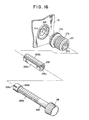
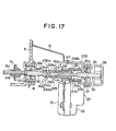
- Figs. 17 and 18 are sectional and perspective views, respectively, showing a fourth embodiment of the present invention. Parts same as those in the above-described embodiments will be denoted by same reference numerals and description on these parts will be omitted.
- Engaging projections 228b and 228b are formed on the back-end (when viewed from the direction of the headlamp or right side in Figs. 17 and 18) of a sleeve 228 and freely slidably fitted into grooves 127d and 127d formed on the inner circumference of a hollow gear 127 and extended in the axial direction thereof.
- the hollow gear 127 and the sleeve 228 can slide freely relative to each other in the axial direction but be prevented from rotating around the axis. It may be arranged in this case that the projections are formed on the hollow gear 127 while the grooves in the sleeve 228.
- An adjusting rod 230 is inserted into the sleeve 228 to freely rotate relative to the latter but prevented from sliding in the axial direction of these members by means of a clip 132.
- the hand-operating shaft 30 is passed through the casing 22 which is opposite to the casing 121 through which the sleeve 228 is screwed and passed, and the collar 30a on the shaft 30 is pressed by the shaft holder 37 through the seal packing 36, so that the shaft 30 can be restricted a little in rotation at its predetermined position and also in movement toward its axial direction.
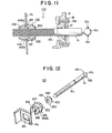
- Fig. 17 is a perspective view showing the female screw hole 121a, hollow gear 127, adjusting rod 230, sleeve 228, clip.131 and shaft 30 dismantled.
- the front end of the shaft 30 which has the knob 38 fixed to the back end thereof is fitted into the adjusting rod 230 in such a way that the former can freely slide in the axial direction relative to the adjusting rod 230 in an insertion hole 230a thereof but be prevented from rotating around the axis of these members.
- the insertion 30b which has a non-circular rectangular section is formed on the front side of the shaft 30 and inserted into an opening 130a in the back end face of the adjusting rod 230 so as to enable both of these members to be freely slid relative to each other.
- an spherical socket portion 230b is formed on the front end face of the adjusting rod 230, and the ball portion 16a formed on the back end-face of the connector rod 16 is fitted into the spherical socket portion 230b of adjusting rod 230, with its projections 16b and 16b received in slits 230c and 230c of the rod 230, so that relative rotation between these rods 230 and 16 can be prevented around the.axis thereof.
- the screw thread 16c of the connector rod .16 is engaged with the screw thread on the inner circumference of the through-hole of the ball joint 150, passing through the lamp housing 3.
- Numeral 17 denotes the water-proof packing, and 18 the holder for attaching the packing 17 to the lamp housing 3.
- the aiming adjustment which is to be done at the time of attaching the headlamps 1 to the car body can be attained as follows: the shaft 30 is rotated by hand; because the adjusting rod 230 is left free from the sleeve 228, it is rotated integral with the shaft 30; the connector rod 16 is thus rotated at its predetermined position; the ball joint 150 which is engaged with the screw portion 16c of the rod 16 is screw-advanced by the connector rod 16; and the mounting 148 follows this advance of the ball joint 150 to swing the reflector 4 around the axis which passes through the fulcrum mechanism and the aiming means 10 (see Fig. 1), thereby enabling the direction of initial light axis to be adjusted.
- the levelling adjustment for adjusting the direction of-light axis which changes depending upon the carrying conditions can be achieved as follows: the hollow gear 127 is rotated by means of the motor 23 and the speed reduction mechanism 24, as shown in Fig. 6; the sleeve 228 is thus rotated and moved front-or backward due to the action of the male screw 228a; the linear movement of the sleeve 228 is transmitted to the connector rod 16 through the adjusting rod 230; and the reflector 4 is swung by the front- or backward movement of the connector rod 16 to return the direction of light axis to its original position.
- a worm gear 127b is formed on the outer circumference of the cylindrical hollow gear 127 and a worm wheel 235 which is engaged with the worm gear 127b is fixed to the axis of a potentiometer 236, as shown in Fig. 18. Therefore, the rotation of the hollow gear 127 can be picked up as an electric signal by the potentiometer 236. Since the rotation angle of the hollow gear 127 is proportional to the advancing and retreating distance of the adjusting and connector rods 230 and 16, the direction of light axis can be detected using the electric signal. Therefore, the electric signal can be used to display and automatically control the direction of light axis.
- the center axis of the worm wheel 235 is made perpendicular to that of the hollow gear 127. Accordingly, any error which acts on the potentiometer 236 can be neglected even when the support of the hollow gear 127 is made with some looseness in the radial direction thereof.
- the present invention has been described referring to the headlamp of the reflector movable type, the light axis adjusting device of the present invention can be applied to the headlamp in which a pre-focus light unit of lens and reflector is incorporated.
Landscapes
- Engineering & Computer Science (AREA)
- Mechanical Engineering (AREA)
- Lighting Device Outwards From Vehicle And Optical Signal (AREA)
- Non-Portable Lighting Devices Or Systems Thereof (AREA)
Applications Claiming Priority (6)
| Application Number | Priority Date | Filing Date | Title |
|---|---|---|---|
| JP3968583U JPS59145432U (ja) | 1983-03-22 | 1983-03-22 | ヘツドランプの光軸調整装置 |
| JP39686/83U | 1983-03-22 | ||
| JP3968683U JPS59145433U (ja) | 1983-03-22 | 1983-03-22 | ヘツドランプの光軸調整装置 |
| JP39685/83U | 1983-03-22 | ||
| JP12616283U JPS6034028U (ja) | 1983-08-16 | 1983-08-16 | ヘツドランプの光軸調整装置 |
| JP126162/83U | 1983-08-16 |
Publications (2)
| Publication Number | Publication Date |
|---|---|
| EP0120442A1 true EP0120442A1 (fr) | 1984-10-03 |
| EP0120442B1 EP0120442B1 (fr) | 1987-12-09 |
Family
ID=27290227
Family Applications (1)
| Application Number | Title | Priority Date | Filing Date |
|---|---|---|---|
| EP84103050A Expired EP0120442B1 (fr) | 1983-03-22 | 1984-03-20 | Dispositif pour régler l'inclinaison de l'axe optique des phares d'un véhicule |
Country Status (3)
| Country | Link |
|---|---|
| US (1) | US4574334A (fr) |
| EP (1) | EP0120442B1 (fr) |
| DE (2) | DE3467990D1 (fr) |
Cited By (11)
| Publication number | Priority date | Publication date | Assignee | Title |
|---|---|---|---|---|
| EP0220068A3 (en) * | 1985-10-18 | 1988-11-09 | Kabushiki Kaisha Toshiba | Headlight unit |
| FR2630980A1 (fr) * | 1988-05-06 | 1989-11-10 | Koito Mfg Co Ltd | Dispositif d'inclinaison de feu avant de vehicule |
| FR2630981A1 (fr) * | 1988-05-07 | 1989-11-10 | Koito Mfg Co Ltd | Dispositif de mise a niveau d'un phare de vehicule |
| FR2631294A1 (fr) * | 1988-05-10 | 1989-11-17 | Koito Mfg Co Ltd | Dispositif d'inclinaison des phares pour vehicules |
| FR2631295A1 (fr) * | 1988-05-10 | 1989-11-17 | Koito Mfg Co Ltd | Dispositif d'inclinaison d'un phare de vehicule |
| WO1990007440A1 (fr) * | 1988-12-30 | 1990-07-12 | Robert Bosch Gmbh | Phare pour vehicules a moteur |
| EP0535472A3 (en) * | 1991-09-30 | 1993-08-11 | Mazda Motor Corporation | A light projecting angle adjusting device for a head lamp of a vehicle |
| FR2736313A1 (fr) * | 1995-07-06 | 1997-01-10 | Valeo Vision | Actionneur, notamment pour la commande de l'orientation d'un projecteur de vehicule automobile |
| EP0716954A3 (fr) * | 1994-12-14 | 1997-03-19 | Ichikoh Industries Ltd | Dispositif de réglage de l'axe optique pour un phare |
| GB2367120A (en) * | 2000-09-25 | 2002-03-27 | Tyc Brother Ind Co Ltd | Apparatus for controlling movement of a lamp unit relative to an automobile body |
| DE102006034243A1 (de) * | 2006-07-21 | 2008-01-31 | Schefenacker Vision Systems Germany Gmbh | Scheinwerferverstellvorrichtung mit Getriebe |
Families Citing this family (57)
| Publication number | Priority date | Publication date | Assignee | Title |
|---|---|---|---|---|
| EP0133576B1 (fr) * | 1983-08-16 | 1991-05-15 | Ichikoh Industries Limited | Dispositif pour ajuster l'axe optique des phares d'un véhicule automobile |
| FR2568525B1 (fr) * | 1984-08-01 | 1987-01-30 | Manzoni Stephane | Dispositif de reglage de la position de projecteurs de vehicules |
| DE3525618A1 (de) * | 1985-07-18 | 1987-01-22 | Bosch Gmbh Robert | Scheinwerfer fuer kraftfahrzeuge |
| US4712164A (en) * | 1986-01-30 | 1987-12-08 | General Motors Corporation | Vehicle headlamp assembly |
| US4703399A (en) * | 1986-07-16 | 1987-10-27 | General Motors Corporation | Vehicle headlamp assembly |
| US4757428A (en) * | 1987-03-03 | 1988-07-12 | Ryder International Corporation | Headlamp mounting assembly |
| US4757429A (en) * | 1987-03-20 | 1988-07-12 | Ryder International Corporation | Adjustment bracket assembly |
| US4731707A (en) * | 1987-05-04 | 1988-03-15 | General Motors Corporation | Vehicle headlamp assembly |
| US4742435A (en) * | 1987-07-27 | 1988-05-03 | General Motors Corporation | Support arrangement for a vehicle headlamp |
| US4845598A (en) * | 1987-09-22 | 1989-07-04 | Koito Seisakusho Co., Ltd. | Headlight for automobile |
| US4881152A (en) * | 1987-09-22 | 1989-11-14 | Koito Seisakusho Co., Ltd. | Headlight for automobile |
| US4882658A (en) * | 1988-08-29 | 1989-11-21 | General Motors Corporation | Headlamp assembly |
| JPH0787041B2 (ja) * | 1988-11-24 | 1995-09-20 | 株式会社小糸製作所 | 前照灯の組立方法 |
| US4939945A (en) * | 1989-04-13 | 1990-07-10 | Ryder International Corp. | Gearbox drive system with plastic output gear |
| FR2662403B1 (fr) * | 1990-05-25 | 1993-12-10 | Valeo Electronique | Actionneur, notamment pour la commande d'orientation d'un projecteur de vehicule automobile. |
| FR2664963B1 (fr) * | 1990-07-23 | 1992-11-13 | Valeo Vision | Projecteur comportant des moyens de reglage d'orientation de faisceau. |
| US5191264A (en) * | 1991-10-22 | 1993-03-02 | Mhs Inc. | Lighting system |
| US5260857A (en) * | 1992-05-27 | 1993-11-09 | Gte Products Corporation | Adjustment linkage for a vehicle headlamp |
| US5319529A (en) * | 1992-05-29 | 1994-06-07 | Gte Products Corporation | Clipped on marker for use with adjustment linkage for a vehicle headlamp |
| US5321589A (en) * | 1992-08-07 | 1994-06-14 | Harada Kogyo Kabushiki Kaisha | Apparatus for controlling irradiation angle of a headlamp light |
| US5526238A (en) * | 1992-12-28 | 1996-06-11 | Ford Motor Company | Adjusting and support apparatus for a lamp unit |
| US5394318A (en) * | 1993-03-31 | 1995-02-28 | Harada Kogyo Kabushiki Kaisha | Device for adjusting and controlling the optical axis of a headlamp |
| US5327330A (en) * | 1993-04-07 | 1994-07-05 | Ford Motor Company | Inner sealed lamp-within-a lamp headlamp for a motor vehicle |
| US5414335A (en) * | 1993-04-08 | 1995-05-09 | Harada Kogyo Kabushiki Kaisha | Device for controlling the angle of the optical axis of a headlamp light |
| US5444603A (en) * | 1993-07-19 | 1995-08-22 | Koito Manufacturing Co., Ltd. | Push-on fixer for screw engagement |
| JPH07320505A (ja) * | 1994-05-19 | 1995-12-08 | Koito Mfg Co Ltd | 自動車用灯具におけるエイミング機構 |
| US5707133A (en) * | 1996-01-11 | 1998-01-13 | Burton Technologies | Automobile headlamp adjuster |
| FR2745061B1 (fr) * | 1996-02-20 | 1998-05-07 | Valeo Vision | Projecteur de vehicule automobile, comportant une source lumineuse unique et susceptible d'emettre un faisceau de croisement et un faisceau de route |
| ES2131471B1 (es) * | 1997-07-30 | 2000-03-01 | Auxiliar De Componentes Electr | Corrector electrico de faro con desplazamiento lineal. |
| US6247868B1 (en) | 1998-02-13 | 2001-06-19 | John E. Burton | Ball socket for pivot joint |
| US6113301A (en) * | 1998-02-13 | 2000-09-05 | Burton; John E. | Disengageable pivot joint |
| US6447154B1 (en) * | 1999-12-03 | 2002-09-10 | Elco Textron Inc. | Headlamp adjuster with overload clutch mechanism |
| US6450674B2 (en) * | 1999-12-03 | 2002-09-17 | Elco Textron Inc. | Headlamp adjuster configured to prevent over-travel of an adjuster output shaft |
| JP2001341577A (ja) * | 2000-05-31 | 2001-12-11 | Mitsubishi Electric Corp | 車両用前照灯システム、及び車両用前照灯の照射軸調整装置 |
| US6758622B2 (en) | 2001-02-16 | 2004-07-06 | Burton Technologies Llc | Ball socket with improved pull-out force resistance |
| FR2826709B1 (fr) * | 2001-06-29 | 2004-02-13 | Valeo Vision | Dispositif d'eclairage a orientation variable |
| US6767118B2 (en) * | 2001-12-13 | 2004-07-27 | Automotive Lighting Reutlingen Gmbh | Device and method for adjusting the direction of light emitted from a motor vehicle headlight |
| US6692176B1 (en) | 2002-04-02 | 2004-02-17 | Asyst Technologies Llc | Ball socket with locking feature |
| JP2003346515A (ja) * | 2002-05-30 | 2003-12-05 | Koito Mfg Co Ltd | 車輌用前照灯のレベリング装置 |
| US20050036331A1 (en) * | 2002-08-09 | 2005-02-17 | Crepeau Jean Phillipe | Modular headlight structure for vehicle and a method for manufacturing the same |
| US6761476B2 (en) | 2002-08-21 | 2004-07-13 | Visteon Global Technologies, Inc. | Multi-axis swivel mechanism |
| US7052164B2 (en) * | 2002-11-12 | 2006-05-30 | Burton Technologies Llc | Gear screw adjuster |
| JP2005014821A (ja) * | 2003-06-27 | 2005-01-20 | Koito Mfg Co Ltd | 自動車用ヘッドランプ |
| US7118259B2 (en) * | 2004-01-07 | 2006-10-10 | Asyst Technologies, Llc | Adjuster and adjuster assembly |
| US7290907B2 (en) * | 2006-02-24 | 2007-11-06 | Honda Motor Co., Ltd | Vehicle headlamp with daytime running light |
| JP5064192B2 (ja) * | 2007-12-04 | 2012-10-31 | スタンレー電気株式会社 | 車両用前照灯の光軸調整装置 |
| JP5045623B2 (ja) * | 2008-09-17 | 2012-10-10 | 市光工業株式会社 | レベリング装置を備える車両用前照灯 |
| JP5507987B2 (ja) * | 2009-12-10 | 2014-05-28 | 株式会社小糸製作所 | 車両用灯具 |
| DE202010004776U1 (de) * | 2010-04-09 | 2011-09-02 | Zumtobel Lighting Gmbh | Leuchte mit schwenkbarer LED |
| US9726356B2 (en) | 2014-01-06 | 2017-08-08 | Nite Ize, Inc. | Systems and methods for a headlamp |
| DE102015103629A1 (de) * | 2015-03-12 | 2016-09-15 | Hella Autotechnik Nova, S.R.O. | Verstellvorrichtung für Scheinwerfer |
| US20160357025A1 (en) * | 2015-06-04 | 2016-12-08 | Valeo North America, Inc. | Automotive lighting device that projects a virtual 3d image or light, while providing a function |
| US10093221B2 (en) | 2015-07-07 | 2018-10-09 | Burton Technologies, Llc | Light module fastening assembly having a snap wedge assembly with ball stud and insert |
| US10400977B2 (en) * | 2017-02-27 | 2019-09-03 | Motor Coach Industries Limited | Quick adjust vehicle headlight assembly |
| CN107246593A (zh) * | 2017-08-11 | 2017-10-13 | 上海小糸车灯有限公司 | 带自密封的球头调光螺钉及其与灯体的配合结构 |
| US10351046B2 (en) | 2017-12-08 | 2019-07-16 | Asyst Technologies, Llc | Lamp adjuster device and method of use |
| EP4479272B1 (fr) * | 2022-02-17 | 2026-02-18 | Hella Gmbh & Co. Kgaa | Projecteur de véhicule |
Citations (3)
| Publication number | Priority date | Publication date | Assignee | Title |
|---|---|---|---|---|
| FR2386856A2 (fr) * | 1977-04-04 | 1978-11-03 | Seim | Perfectionnements a un dispositif de commande en position d'un accessoire automobile tel que par exemple un volet de chauffage |
| GB2025598A (en) * | 1978-07-13 | 1980-01-23 | Bosch Gmbh Robert | Device for adjusting the headlamps of a motor vehicle |
| GB2089958A (en) * | 1980-12-23 | 1982-06-30 | Bosch Gmbh Robert | Electrical adjusting device for headlamps of motor vehicles |
Family Cites Families (4)
| Publication number | Priority date | Publication date | Assignee | Title |
|---|---|---|---|---|
| JPS5623697Y2 (fr) * | 1977-09-26 | 1981-06-03 | ||
| DE2803089A1 (de) * | 1978-01-25 | 1979-07-26 | Rau Swf Autozubehoer | Einrichtung zum verstellen eines beweglichen elementes |
| DE2847908C3 (de) * | 1978-11-04 | 1981-04-30 | Ford-Werke Ag, 5000 Koeln | Blinkleuchte-Scheinwerfer-Befestigung in Kraftfahrzeugkarosserien |
| DE2847990C3 (de) * | 1978-11-06 | 1981-04-02 | Ford-Werke AG, 5000 Köln | Einstelleinrichtung für Scheinwerfer von Kraftfahrzeugen |
-
1984
- 1984-03-20 DE DE8484103050T patent/DE3467990D1/de not_active Expired
- 1984-03-20 DE DE198484103050T patent/DE120442T1/de active Pending
- 1984-03-20 EP EP84103050A patent/EP0120442B1/fr not_active Expired
- 1984-03-21 US US06/591,830 patent/US4574334A/en not_active Expired - Fee Related
Patent Citations (3)
| Publication number | Priority date | Publication date | Assignee | Title |
|---|---|---|---|---|
| FR2386856A2 (fr) * | 1977-04-04 | 1978-11-03 | Seim | Perfectionnements a un dispositif de commande en position d'un accessoire automobile tel que par exemple un volet de chauffage |
| GB2025598A (en) * | 1978-07-13 | 1980-01-23 | Bosch Gmbh Robert | Device for adjusting the headlamps of a motor vehicle |
| GB2089958A (en) * | 1980-12-23 | 1982-06-30 | Bosch Gmbh Robert | Electrical adjusting device for headlamps of motor vehicles |
Cited By (13)
| Publication number | Priority date | Publication date | Assignee | Title |
|---|---|---|---|---|
| EP0220068A3 (en) * | 1985-10-18 | 1988-11-09 | Kabushiki Kaisha Toshiba | Headlight unit |
| FR2630980A1 (fr) * | 1988-05-06 | 1989-11-10 | Koito Mfg Co Ltd | Dispositif d'inclinaison de feu avant de vehicule |
| FR2630981A1 (fr) * | 1988-05-07 | 1989-11-10 | Koito Mfg Co Ltd | Dispositif de mise a niveau d'un phare de vehicule |
| FR2631294A1 (fr) * | 1988-05-10 | 1989-11-17 | Koito Mfg Co Ltd | Dispositif d'inclinaison des phares pour vehicules |
| FR2631295A1 (fr) * | 1988-05-10 | 1989-11-17 | Koito Mfg Co Ltd | Dispositif d'inclinaison d'un phare de vehicule |
| WO1990007440A1 (fr) * | 1988-12-30 | 1990-07-12 | Robert Bosch Gmbh | Phare pour vehicules a moteur |
| EP0535472A3 (en) * | 1991-09-30 | 1993-08-11 | Mazda Motor Corporation | A light projecting angle adjusting device for a head lamp of a vehicle |
| EP0716954A3 (fr) * | 1994-12-14 | 1997-03-19 | Ichikoh Industries Ltd | Dispositif de réglage de l'axe optique pour un phare |
| DE19626018B4 (de) * | 1995-06-06 | 2007-03-15 | Valeo Vision | Steuereinrichtung, insbesondere für die Steuerung der Lichtstrahlrichtung eines Kraftfahrzeugscheinwerfers |
| FR2736313A1 (fr) * | 1995-07-06 | 1997-01-10 | Valeo Vision | Actionneur, notamment pour la commande de l'orientation d'un projecteur de vehicule automobile |
| GB2367120A (en) * | 2000-09-25 | 2002-03-27 | Tyc Brother Ind Co Ltd | Apparatus for controlling movement of a lamp unit relative to an automobile body |
| GB2367120B (en) * | 2000-09-25 | 2004-12-29 | Tyc Brother Ind Co Ltd | Apparatus for controlling movement of a lamp unit relative to an Automobile body |
| DE102006034243A1 (de) * | 2006-07-21 | 2008-01-31 | Schefenacker Vision Systems Germany Gmbh | Scheinwerferverstellvorrichtung mit Getriebe |
Also Published As
| Publication number | Publication date |
|---|---|
| DE120442T1 (de) | 1985-05-09 |
| DE3467990D1 (en) | 1988-01-21 |
| US4574334A (en) | 1986-03-04 |
| EP0120442B1 (fr) | 1987-12-09 |
Similar Documents
| Publication | Publication Date | Title |
|---|---|---|
| US4574334A (en) | Device for adjusting the inclination of the light axis of headlamps of a motor vehicle | |
| US7517123B2 (en) | Motorized lamp adjuster | |
| US4524407A (en) | Device for adjusting the inclination of the light axis of a headlamp for motor vehicles | |
| US5381317A (en) | Snap-fit right angle adjustor mechanism | |
| US5908239A (en) | Aiming mechanism for vehicle lamps | |
| US5186531A (en) | Headlamp adjuster | |
| CA2133944C (fr) | Assemblage de phare de vehicule | |
| US5070433A (en) | Headlight for a motor vehicle having an adjustable motor-driven reflector | |
| EP0138217A2 (fr) | Dispositif de commande de l'inclinaison des phares d'un véhicule | |
| KR100563497B1 (ko) | 미러 구동 장치 | |
| US3742204A (en) | Knob assemblies for gear-selector levers in motor vehicles | |
| GB2089958A (en) | Electrical adjusting device for headlamps of motor vehicles | |
| JPH0214939A (ja) | 自動車用の前照灯 | |
| KR0173817B1 (ko) | 전조등의 광축조정장치 | |
| GB2253900A (en) | Headlamp levelling mechanism | |
| EP1588092B1 (fr) | Ajusteur sur 180 degres | |
| CA2151444A1 (fr) | Indicateur de position initiale horizontale | |
| JP2534536B2 (ja) | 前照灯装置 | |
| JPH0226755Y2 (fr) | ||
| CN223048652U (zh) | 电动撑杆装置及车辆 | |
| US1369722A (en) | Adjustable lamp and support for headlights | |
| JP3013146B2 (ja) | 自動車用前照灯 | |
| JPS5913166Y2 (ja) | 前照灯取付装置 | |
| CN118653759A (zh) | 电动撑杆装置及车辆 | |
| JPS598544A (ja) | ヘツドランプ傾動装置 |
Legal Events
| Date | Code | Title | Description |
|---|---|---|---|
| PUAI | Public reference made under article 153(3) epc to a published international application that has entered the european phase |
Free format text: ORIGINAL CODE: 0009012 |
|
| AK | Designated contracting states |
Designated state(s): DE FR GB |
|
| EL | Fr: translation of claims filed | ||
| DET | De: translation of patent claims | ||
| 17P | Request for examination filed |
Effective date: 19850401 |
|
| RAP1 | Party data changed (applicant data changed or rights of an application transferred) |
Owner name: ICHIKOH INDUSTRIES LIMITED |
|
| GRAA | (expected) grant |
Free format text: ORIGINAL CODE: 0009210 |
|
| RAP1 | Party data changed (applicant data changed or rights of an application transferred) |
Owner name: ICHIKOH INDUSTRIES LIMITED |
|
| RAP1 | Party data changed (applicant data changed or rights of an application transferred) |
Owner name: ICHIKOH INDUSTRIES LIMITED |
|
| AK | Designated contracting states |
Kind code of ref document: B1 Designated state(s): DE FR GB |
|
| ET | Fr: translation filed | ||
| REF | Corresponds to: |
Ref document number: 3467990 Country of ref document: DE Date of ref document: 19880121 |
|
| PLBE | No opposition filed within time limit |
Free format text: ORIGINAL CODE: 0009261 |
|
| STAA | Information on the status of an ep patent application or granted ep patent |
Free format text: STATUS: NO OPPOSITION FILED WITHIN TIME LIMIT |
|
| 26N | No opposition filed | ||
| PGFP | Annual fee paid to national office [announced via postgrant information from national office to epo] |
Ref country code: FR Payment date: 19980310 Year of fee payment: 15 |
|
| PGFP | Annual fee paid to national office [announced via postgrant information from national office to epo] |
Ref country code: GB Payment date: 19980311 Year of fee payment: 15 |
|
| PGFP | Annual fee paid to national office [announced via postgrant information from national office to epo] |
Ref country code: DE Payment date: 19980327 Year of fee payment: 15 |
|
| PG25 | Lapsed in a contracting state [announced via postgrant information from national office to epo] |
Ref country code: GB Free format text: LAPSE BECAUSE OF NON-PAYMENT OF DUE FEES Effective date: 19990320 |
|
| GBPC | Gb: european patent ceased through non-payment of renewal fee |
Effective date: 19990320 |
|
| PG25 | Lapsed in a contracting state [announced via postgrant information from national office to epo] |
Ref country code: FR Free format text: LAPSE BECAUSE OF NON-PAYMENT OF DUE FEES Effective date: 19991130 |
|
| REG | Reference to a national code |
Ref country code: FR Ref legal event code: ST |
|
| PG25 | Lapsed in a contracting state [announced via postgrant information from national office to epo] |
Ref country code: DE Free format text: LAPSE BECAUSE OF NON-PAYMENT OF DUE FEES Effective date: 20000101 |