EP0120507B1 - Energiesparende Schaltvorrichtung - Google Patents
Energiesparende Schaltvorrichtung Download PDFInfo
- Publication number
- EP0120507B1 EP0120507B1 EP84200093A EP84200093A EP0120507B1 EP 0120507 B1 EP0120507 B1 EP 0120507B1 EP 84200093 A EP84200093 A EP 84200093A EP 84200093 A EP84200093 A EP 84200093A EP 0120507 B1 EP0120507 B1 EP 0120507B1
- Authority
- EP
- European Patent Office
- Prior art keywords
- switching device
- microphone
- energy
- switching
- key
- Prior art date
- Legal status (The legal status is an assumption and is not a legal conclusion. Google has not performed a legal analysis and makes no representation as to the accuracy of the status listed.)
- Expired
Links
Images
Classifications
-
- H—ELECTRICITY
- H05—ELECTRIC TECHNIQUES NOT OTHERWISE PROVIDED FOR
- H05B—ELECTRIC HEATING; ELECTRIC LIGHT SOURCES NOT OTHERWISE PROVIDED FOR; CIRCUIT ARRANGEMENTS FOR ELECTRIC LIGHT SOURCES, IN GENERAL
- H05B47/00—Circuit arrangements for operating light sources in general, i.e. where the type of light source is not relevant
- H05B47/10—Controlling the light source
- H05B47/105—Controlling the light source in response to determined parameters
- H05B47/115—Controlling the light source in response to determined parameters by determining the presence or movement of objects or living beings
- H05B47/12—Controlling the light source in response to determined parameters by determining the presence or movement of objects or living beings by detecting audible sound
-
- Y—GENERAL TAGGING OF NEW TECHNOLOGICAL DEVELOPMENTS; GENERAL TAGGING OF CROSS-SECTIONAL TECHNOLOGIES SPANNING OVER SEVERAL SECTIONS OF THE IPC; TECHNICAL SUBJECTS COVERED BY FORMER USPC CROSS-REFERENCE ART COLLECTIONS [XRACs] AND DIGESTS
- Y02—TECHNOLOGIES OR APPLICATIONS FOR MITIGATION OR ADAPTATION AGAINST CLIMATE CHANGE
- Y02B—CLIMATE CHANGE MITIGATION TECHNOLOGIES RELATED TO BUILDINGS, e.g. HOUSING, HOUSE APPLIANCES OR RELATED END-USER APPLICATIONS
- Y02B20/00—Energy efficient lighting technologies, e.g. halogen lamps or gas discharge lamps
- Y02B20/40—Control techniques providing energy savings, e.g. smart controller or presence detection
Definitions
- This invention relates to an energy-saving switching device for automatically switching off electrical devices (v), in particular lamps, comprising a microphone (1), an electronic circuit (8, 9,10, 20), and frequency filter means (4) connected between the microphone (1) and the electronic circuit (8, 9, 10, 20), wherein the electronic circuit in operation upon receiving via the frequency filter means (4) a signal from the microphone (11) will provide control signals for a relay (11), by means of which in use at least one electrical device (v) is connected to the mains voltage (N).
- a problem with the known energy-saving switching device is that in practice not all kinds of human activity is detected which results in for instance switching off the lights in a room while a person is still present in said room.
- a switching device of the kind described is characterized in that the frequency filter means (4) have a pass band range of substantially 3800 Hz, having a lower frequency limit of substantially 200 Hz and a upper frequency limit of substantially 4000 Hz.
- switching devices per se have been designed for a specific purpose, such as switching off the pump of a central heating installation, or switching off a refrigerator. These known switching devices, however, are only suitable for use together with a specific electrical apparatus.
- US-A-4 099 168 an intrusion alarm device is known which will switch on lights and/or other electrical apparatus when sound indicating an intrusion are detected.
- the intrusion alarm device has a frequency pass band of 500-10.000 Hz. Together with a rate of rise detector this pass band would according to US-A-4 099 168 provide for an effective detection of intrusion-connected sounds such as breaking glass and the like.
- the switching device according to the present invention is particularly suitable for switching off the lighting in unused spaces, and is in addition designed to be built-in in conventional standard assembly boxes.
- the switching device according to the invention permits being connected to both individual consumers and groups of consumers.
- the switching device according to the invention is arranged so that, in response to sound caused by human beings and after the "on" key has been depressed, the lamps connected to the switching device are switched on.
- the switching device may be arranged so that the switching device does not become operative unless in the absence of sufficient day-light and in the presence of sound caused by human beings and after the "on" key has been depressed.
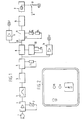
- the switching device shown in Figure 1 comprises a microphone 1, which at choice may be placed either together with the remainder of the switching device in one housing or elsewhere.
- the microphone 1 is connected via an amplifier 3, provided with a voltage divider 2 for setting its sensitivity, to a frequency filter 4 having such characteristics as to pass only frequencies associated with sounds to which the switching device should respond.
- the filter has a pass band of 200 ⁇ 4000 Hz.
- the output signal from filter 4 is supplied via a flip-flop 5 to a holding circuit 6 with a holding period of, for example, 4 minutes, adjustable by means of an adjusting device 7. This means that, if no acoustic signal is received for more than four minutes after receiving an acoustic signal, the output signal from the holding circuit drops to zero.
- the output of the holding circuit is connected to one input of a flip-flop 8.
- Flip-flop 8 can only give off an output signal in response to a signal provided by the holding circuit if first an "on” key 9, shown diagrammatically, has been depressed.
- the "on” key also serves as an "off” key.
- This combined "on/off” key is connected to a flip-flop 20, which serves as an anti-contact-bouncing circuit 20.
- the whole unit, i.e. the "on/off” key 9 plus the anti-contact-bouncing circuit 20 is referred to hereinafter as the combined "on/off” key 9/20.
- the output of flip-flop 8 causes, via a control circuit 10, the energization of a relay 11, one or more contacts 12 of which can connect one or more consumers V to the mains voltage N.
- LED L 1 only burns if the combined "on/off" key 9/20 has been depressed and sound is present, and accordingly indicates that the switching device is in operation.
- a red LED L 2 is provided, which via an amplifier 14 is connected to the output of the holding circuit 6 to indicate that sound has been detected.
- the circuit arrangement as described hereinbefore is only responsive to sound.
- the switching device may also be designed to respond to sound only if there is insufficient day-light.
- Figure 1 shows a light-sensitive element, for example, an LDR 15, which is connected to a voltage divider 16 for setting a threshold level, and connected to an AND gate 18 having an inverting input 17.
- the other input 19 of the AND gate is connected to the output of flip-flop 8, so that the AND gate only gives off an output signal if there is sound in the absence of sufficient light.
- the output of the AND gate is in turn connected to the circuit 10.
- the unit When the light has been switched on (LDR is then out of operation) the unit only responds to sound (Reset). If desired, the LDR may be placed at a remote point (Outside). The microphone, too, may be placed at a remote point, should this be desired.
- Figure 2 shows an elevational view of an example of a device shown in Figure 1, placed in a standard assembly box.
- the LED designated by L1 Disposed behind the window of the combined "on/off" key designated by 9/20 is the LED designated by L1, the microphone designated by 1, and the light-sensitive element, designated by 15. These elements are placed in a cover plate (except for the red LED indicated by L2, which is disposed under the cover plate) of standard dimensions, and mounted on a standard assembly box in the usual way, with the other parts of the circuit arrangement being housed in the subjacent assembly box and, if necessary, in standard assembly boxes connected to this.
- similar cover plates may be formed without a light-sensitive element, or only with a microphone.
Landscapes
- Circuit Arrangement For Electric Light Sources In General (AREA)
- Switch Cases, Indication, And Locking (AREA)
- Keying Circuit Devices (AREA)
- Oscillators With Electromechanical Resonators (AREA)
- Electronic Switches (AREA)
Claims (1)
- Energiesparende Schaltvorrichtung zum automatischen Ausschalten von elektrischen Vorrichtungen (v), insbesondere Lampen, versehen mit einem Mikrophon (1), einem elektronischen Kreis (8, 9, 10, 20) und Frequenzfiltermitteln (4), die zwischen das Mikrophon (1) und den elektronischen Kreis (8, 9, 10, 20) geschaltet sind, wobei der elektronische Kreis im Betrieb beim Empfangen eines Signals vom Mikrophon (1) über die Frequenzfiltermittel (4) Steuersignale für ein Relais (11) erzeugt, durch welches im Betrieb mindestens eine elektrische Vorrichtung (v) an die Netzspannung (N) angeschlossen ist, dadurch gekennzeichnet, dass die Frequenzfiltermittel (4) einen Durchlassbereich von im wesentlichen 3800 Hz aufweisen, mit einer unteren Frequenzgrenze von im wesentlichen 200 Hz und einer oberen Frequenzgrenze von im wesentlichen 4000 Hz.
Priority Applications (1)
| Application Number | Priority Date | Filing Date | Title |
|---|---|---|---|
| AT84200093T ATE43468T1 (de) | 1983-01-25 | 1984-01-24 | Energiesparende schaltvorrichtung. |
Applications Claiming Priority (2)
| Application Number | Priority Date | Filing Date | Title |
|---|---|---|---|
| NL8300270A NL8300270A (nl) | 1983-01-25 | 1983-01-25 | Energie besparende schakelinrichting. |
| NL8300270 | 1983-01-25 |
Publications (2)
| Publication Number | Publication Date |
|---|---|
| EP0120507A1 EP0120507A1 (de) | 1984-10-03 |
| EP0120507B1 true EP0120507B1 (de) | 1989-05-24 |
Family
ID=19841287
Family Applications (1)
| Application Number | Title | Priority Date | Filing Date |
|---|---|---|---|
| EP84200093A Expired EP0120507B1 (de) | 1983-01-25 | 1984-01-24 | Energiesparende Schaltvorrichtung |
Country Status (4)
| Country | Link |
|---|---|
| EP (1) | EP0120507B1 (de) |
| AT (1) | ATE43468T1 (de) |
| DE (1) | DE3478383D1 (de) |
| NL (1) | NL8300270A (de) |
Families Citing this family (5)
| Publication number | Priority date | Publication date | Assignee | Title |
|---|---|---|---|---|
| JPH01230577A (ja) * | 1987-11-10 | 1989-09-14 | Nippon Tokushu Noyaku Seizo Kk | 3−置換−ピリジン類及び農園芸用殺菌除草剤 |
| GB8826714D0 (en) * | 1988-11-15 | 1988-12-21 | Waverlink Electronics Ltd | Sound sensitive electrical switch |
| CA2084241C (en) * | 1992-12-01 | 1999-01-19 | William Randall Erwin | Audible alert for automatic shutoff circuit |
| GB0507531D0 (en) * | 2005-04-14 | 2005-05-18 | Green Roger | Power saving device |
| FI20065263A7 (fi) * | 2006-04-25 | 2007-10-26 | Innohome Oy | Järjestelmä sähkön-, veden- tai kaasunsyötön ohjaamiseksi |
Family Cites Families (8)
| Publication number | Priority date | Publication date | Assignee | Title |
|---|---|---|---|---|
| US3748496A (en) * | 1971-10-26 | 1973-07-24 | R Hedin | Sound activated controller |
| US3893081A (en) * | 1974-04-05 | 1975-07-01 | Charles L Hopkins | Audio actuated lamp |
| JPS5244387A (en) * | 1975-10-06 | 1977-04-07 | Hitachi Ltd | Power source switch circuit used for a remote-controlled electric apparatus |
| US4099168A (en) * | 1975-11-06 | 1978-07-04 | Magnum Products, Inc. | Intrusion alarm and emergency illumination apparatus and method |
| DE2832874A1 (de) * | 1978-07-27 | 1980-02-14 | Bbc Brown Boveri & Cie | Anordnung fuer einen treppenlichtzeitschalter |
| US4361767A (en) * | 1980-03-24 | 1982-11-30 | National Technical Systems | Apparatus and method for controlling electrical equipment |
| US4344071A (en) * | 1980-07-10 | 1982-08-10 | Roger A. Heller | Light switching mechanism |
| US4408308A (en) * | 1981-06-16 | 1983-10-04 | Ehrenreich Electronics, Inc. | Sound actuated light switch |
-
1983
- 1983-01-25 NL NL8300270A patent/NL8300270A/nl not_active Application Discontinuation
-
1984
- 1984-01-24 AT AT84200093T patent/ATE43468T1/de not_active IP Right Cessation
- 1984-01-24 EP EP84200093A patent/EP0120507B1/de not_active Expired
- 1984-01-24 DE DE8484200093T patent/DE3478383D1/de not_active Expired
Also Published As
| Publication number | Publication date |
|---|---|
| DE3478383D1 (en) | 1989-06-29 |
| EP0120507A1 (de) | 1984-10-03 |
| ATE43468T1 (de) | 1989-06-15 |
| NL8300270A (nl) | 1984-08-16 |
Similar Documents
| Publication | Publication Date | Title |
|---|---|---|
| US3522595A (en) | Self-contained fire detecting and warning apparatus | |
| US3611333A (en) | Mailbox operated electronic signal device | |
| US5283816A (en) | Smoke detector using telephone link | |
| FI100836B (fi) | Testin käynnistämislaite jatkuvalla tai pulssitulolla | |
| US4476554A (en) | Sound actuated light switch | |
| EP0067502B1 (de) | Schallgesteuerter Lichtschalter | |
| US6172612B1 (en) | Smoke detector with remote testing, shutoff and powering means | |
| CA1169938A (en) | Alarm system having plural diverse detection means | |
| US3836901A (en) | Motion-sensitive alarm with line-cord-responsive automatic arming means | |
| US4360856A (en) | Electric sensor package | |
| US4186389A (en) | Sleeper's smoke-alarm clock | |
| US4839562A (en) | Electrical devices | |
| US4524304A (en) | Smoke alarm activated light | |
| US4680576A (en) | Photoelectric smoke detector and alarm system | |
| US3624635A (en) | Distress signal | |
| US4812821A (en) | Visual fire alert system | |
| US4287509A (en) | Sound and light signaling system | |
| US3781842A (en) | Intrusion detecting apparatus and method | |
| EP0120507A1 (de) | Energiesparende Schaltvorrichtung | |
| CA1071731A (en) | Apparatus for supervising leads interconnecting a plurality of self-contained abnormal condition sensing and alarm annunciating units | |
| JPS59173898A (ja) | 家庭用などの火災報知機 | |
| USRE28915E (en) | Detection of products of combustion | |
| GB2141853A (en) | Improvements in or relating to automatic light switches | |
| US3801971A (en) | Telephone alarm system | |
| EP0318710A1 (de) | Gefahrenmeldezentrale |
Legal Events
| Date | Code | Title | Description |
|---|---|---|---|
| PUAI | Public reference made under article 153(3) epc to a published international application that has entered the european phase |
Free format text: ORIGINAL CODE: 0009012 |
|
| AK | Designated contracting states |
Designated state(s): AT BE CH DE FR GB IT LI NL SE |
|
| 17P | Request for examination filed |
Effective date: 19850329 |
|
| 17Q | First examination report despatched |
Effective date: 19870312 |
|
| GRAA | (expected) grant |
Free format text: ORIGINAL CODE: 0009210 |
|
| AK | Designated contracting states |
Kind code of ref document: B1 Designated state(s): AT BE CH DE FR GB IT LI NL SE |
|
| PG25 | Lapsed in a contracting state [announced via postgrant information from national office to epo] |
Ref country code: SE Effective date: 19890524 Ref country code: LI Effective date: 19890524 Ref country code: CH Effective date: 19890524 Ref country code: AT Effective date: 19890524 |
|
| REF | Corresponds to: |
Ref document number: 43468 Country of ref document: AT Date of ref document: 19890615 Kind code of ref document: T |
|
| REF | Corresponds to: |
Ref document number: 3478383 Country of ref document: DE Date of ref document: 19890629 |
|
| ITF | It: translation for a ep patent filed | ||
| RAP2 | Party data changed (patent owner data changed or rights of a patent transferred) |
Owner name: WIJK, WILLEM MECHIEL |
|
| ET | Fr: translation filed | ||
| REG | Reference to a national code |
Ref country code: CH Ref legal event code: PL |
|
| NLT2 | Nl: modifications (of names), taken from the european patent patent bulletin |
Owner name: WILLEM MECHIEL WIJK TE HAREN. |
|
| BECN | Be: change of holder's name |
Effective date: 19890524 |
|
| PGFP | Annual fee paid to national office [announced via postgrant information from national office to epo] |
Ref country code: FR Payment date: 19900130 Year of fee payment: 7 |
|
| ITTA | It: last paid annual fee | ||
| PGFP | Annual fee paid to national office [announced via postgrant information from national office to epo] |
Ref country code: GB Payment date: 19900131 Year of fee payment: 7 |
|
| PGFP | Annual fee paid to national office [announced via postgrant information from national office to epo] |
Ref country code: BE Payment date: 19900206 Year of fee payment: 7 |
|
| PLBE | No opposition filed within time limit |
Free format text: ORIGINAL CODE: 0009261 |
|
| STAA | Information on the status of an ep patent application or granted ep patent |
Free format text: STATUS: NO OPPOSITION FILED WITHIN TIME LIMIT |
|
| 26N | No opposition filed | ||
| PG25 | Lapsed in a contracting state [announced via postgrant information from national office to epo] |
Ref country code: GB Effective date: 19910124 |
|
| PG25 | Lapsed in a contracting state [announced via postgrant information from national office to epo] |
Ref country code: BE Effective date: 19910131 |
|
| PGFP | Annual fee paid to national office [announced via postgrant information from national office to epo] |
Ref country code: NL Payment date: 19910131 Year of fee payment: 8 |
|
| PGFP | Annual fee paid to national office [announced via postgrant information from national office to epo] |
Ref country code: DE Payment date: 19910319 Year of fee payment: 8 |
|
| GBPC | Gb: european patent ceased through non-payment of renewal fee | ||
| PG25 | Lapsed in a contracting state [announced via postgrant information from national office to epo] |
Ref country code: FR Effective date: 19910930 |
|
| REG | Reference to a national code |
Ref country code: FR Ref legal event code: ST |
|
| PG25 | Lapsed in a contracting state [announced via postgrant information from national office to epo] |
Ref country code: NL Effective date: 19920801 |
|
| NLV4 | Nl: lapsed or anulled due to non-payment of the annual fee | ||
| PG25 | Lapsed in a contracting state [announced via postgrant information from national office to epo] |
Ref country code: DE Effective date: 19921001 |