EP0120733A1 - Vorrichtung zur Brennstoffvorwärmung eines Dieselmotors - Google Patents
Vorrichtung zur Brennstoffvorwärmung eines Dieselmotors Download PDFInfo
- Publication number
- EP0120733A1 EP0120733A1 EP84400331A EP84400331A EP0120733A1 EP 0120733 A1 EP0120733 A1 EP 0120733A1 EP 84400331 A EP84400331 A EP 84400331A EP 84400331 A EP84400331 A EP 84400331A EP 0120733 A1 EP0120733 A1 EP 0120733A1
- Authority
- EP
- European Patent Office
- Prior art keywords
- circuit
- fuel
- exchanger
- oil
- channels
- Prior art date
- Legal status (The legal status is an assumption and is not a legal conclusion. Google has not performed a legal analysis and makes no representation as to the accuracy of the status listed.)
- Granted
Links
Images


Classifications
-
- F—MECHANICAL ENGINEERING; LIGHTING; HEATING; WEAPONS; BLASTING
- F02—COMBUSTION ENGINES; HOT-GAS OR COMBUSTION-PRODUCT ENGINE PLANTS
- F02M—SUPPLYING COMBUSTION ENGINES IN GENERAL WITH COMBUSTIBLE MIXTURES OR CONSTITUENTS THEREOF
- F02M31/00—Apparatus for thermally treating combustion-air, fuel, or fuel-air mixture
- F02M31/02—Apparatus for thermally treating combustion-air, fuel, or fuel-air mixture for heating
- F02M31/16—Other apparatus for heating fuel
-
- F—MECHANICAL ENGINEERING; LIGHTING; HEATING; WEAPONS; BLASTING
- F02—COMBUSTION ENGINES; HOT-GAS OR COMBUSTION-PRODUCT ENGINE PLANTS
- F02M—SUPPLYING COMBUSTION ENGINES IN GENERAL WITH COMBUSTIBLE MIXTURES OR CONSTITUENTS THEREOF
- F02M31/00—Apparatus for thermally treating combustion-air, fuel, or fuel-air mixture
- F02M31/02—Apparatus for thermally treating combustion-air, fuel, or fuel-air mixture for heating
- F02M31/04—Apparatus for thermally treating combustion-air, fuel, or fuel-air mixture for heating combustion-air or fuel-air mixture
- F02M31/10—Apparatus for thermally treating combustion-air, fuel, or fuel-air mixture for heating combustion-air or fuel-air mixture by hot liquids, e.g. lubricants or cooling water
- F02M31/102—Particular constructional characteristics of the shape of the heat exchange surfaces
-
- F—MECHANICAL ENGINEERING; LIGHTING; HEATING; WEAPONS; BLASTING
- F02—COMBUSTION ENGINES; HOT-GAS OR COMBUSTION-PRODUCT ENGINE PLANTS
- F02B—INTERNAL-COMBUSTION PISTON ENGINES; COMBUSTION ENGINES IN GENERAL
- F02B3/00—Engines characterised by air compression and subsequent fuel addition
- F02B3/06—Engines characterised by air compression and subsequent fuel addition with compression ignition
-
- Y—GENERAL TAGGING OF NEW TECHNOLOGICAL DEVELOPMENTS; GENERAL TAGGING OF CROSS-SECTIONAL TECHNOLOGIES SPANNING OVER SEVERAL SECTIONS OF THE IPC; TECHNICAL SUBJECTS COVERED BY FORMER USPC CROSS-REFERENCE ART COLLECTIONS [XRACs] AND DIGESTS
- Y02—TECHNOLOGIES OR APPLICATIONS FOR MITIGATION OR ADAPTATION AGAINST CLIMATE CHANGE
- Y02T—CLIMATE CHANGE MITIGATION TECHNOLOGIES RELATED TO TRANSPORTATION
- Y02T10/00—Road transport of goods or passengers
- Y02T10/10—Internal combustion engine [ICE] based vehicles
- Y02T10/12—Improving ICE efficiencies
Definitions
- the present invention relates to a method and a heat exchange device, in particular for heating fuel in engines, in particular diesel.
- the reheating must bring the fuel to the temperature of at least 70 to 80 ° C.
- the water in the engine cooling system first appears as a convenient or at least free evening of calories.
- thought has already been given to using the engine cooling water to heat the fuel in cold weather see FR A 81 13417 of 7/07/81 in the name of the applicant).
- heat exchanges are carried out simultaneously between the fuel to be heated, the lubricating oil and the engine cooling water.
- the lubricating oil can reach temperatures during the normal operation of the engine of the order of 100 to 40 ° C. We thus have a very wide range of hot temperatures.
- the fuel re-heating temperature at a temperature equal to or higher than that of the water in the cooling circuit, and up to a higher temperature at 100 ° C.
- the invention also relates to a device for heating the fuel incorporating a heat exchanger comprising three circuits: a water (or other liquid) circuit for cooling the engine, a fuel circuit (diesel) and an oil circuit, heat exchange surfaces being provided between the oil circuit and the fuel circuit, between the water circuit and the fuel circuit and between the oil circuit and the water circuit.
- the device according to the invention is used simultaneously for heating fuel, more particularly diesel for diesel engines and for cooling oil. It is placed on the diesel circuit. Depending on the case, it can be placed upstream or downstream of the injection pump as explained in the applicant's previous patent, referenced above. In the following example, the device according to the invention is mounted upstream of the injection system.
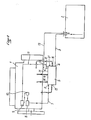
- FIG. 1 there is shown schematically an engine 1, equipped with a device according to the invention.
- the diesel tank 2 is connected by a pipe 3 to the inlet 4 of an exchanger device 5 according to the invention.
- the heated diesel oil leaves at 6 and is sent via line 7 first to the feed pump 8, then to the injection pump 9 after passing through the filter 10.
- a return line 11 brings back to the inlet 12 the excess diesel from the injection pump, and a pipe 13 returns to the tank the excess diesel from the outlet 14 of the exchanger.
- the exchanger also has an inlet 15 and an outlet 16 for water, and an inlet 18 and an outlet 19 for oil. These inputs and outputs 15, 16, 18, 19 are suitably connected to the corresponding circuits.
- an electrical outlet 21 makes it possible to connect a heating resistor provided inside the device.
- a reservoir 23 is associated with the exchanger.
- This tank which may include a heating coil 27 or any other heating means keeps a quantity of diesel at the right temperature when the engine is stopped, to allow starting in the best conditions. It also allows additional heating when the outside temperature is very low.
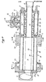
- the device 5 as shown in Figures 2 to 4 has two parts: a heat exchanger 22, on the left of the figure and a preheating tank 23 on the right. These two parts are substantially cylindrical and arranged one after the other along the same axis. This is just an example. The two parts could have different shapes from the cylinder, and different from each other. The tank could be placed around the exchanger for example.
- the water passes successively the exchanger 22 and the reservoir 23 passing through the center of these.
- the water enters hot (in engine operating conditions) at 15 to the left and exits to the right at 16.
- the preheating tank defines a volume 24 arranged around the water tube 25.
- a fuel inlet 4 is preferably provided at a point away from the exchanger to avoid stagnation zones, and an outlet 26 communicates the volume 24 with the exchanger 22.
- a heating coil 27, with a suitable connection 21, is arranged inside the tank 23 in the volume 24.
- the heating coil has an electrical resistance and a thermal regulation ensuring the maintenance at a chosen temperature of the diesel enclosed in the reservoir 23. This temperature will advantageously be lower than the temperature for reheating diesel fuel under normal conditions. Starting will be easier, and the coil will automatically heat up, if for example due to very harsh weather conditions, the heating by the exchanger was not sufficient.
- the exchanger comprises a bundle of parallel channels (AX) with connections at the ends of the bundle to determine three circuits for the inlet 57, 58 and the outlet 76, 71 of the oil, l inlet 15 and outlet 16 for water, inlet 26 bis and outlet 47 for fuel, each of the circuits comprising at least one path of the channel bundle along its length and connections 41, 42, 44, 59, 61, 72, 73, 74, at the ends of the bundle to constitute at least one circuit comprising at least two routes of the length.
- the exchanger comprises a central channel 31 delimited by a substantially circular wall 32, provided with fins 33 oriented towards the center of the channel 31.
- the fins have a surface ribbed, grooved or knurled to increase the heat exchange surface.
- the exchanger is delimited by an envelope 35, which can be cylindrical. Space between the wall 32 of the central channel and the casing 35 is divided into twenty four channels, referenced A to X, some of which are used for the circulation of oil and others for the circulation of diesel. The walls separating the channels are ridged to increase the heat exchange surface.
- the ends of the exchanger are closed by flanges in the form of plates or flanges 37 on the left and 38 on the right.
- openings can be made at the two ends of the exchanger in the flanges 37, 38 and / or in the casing 35 and these openings are properly connected together and to the circuits correspondents. It is thus possible to arrange the oil and the diesel alternately in one channel out of two or in pairs of channels alternately.
- the cavities can be perforations closed towards the outside by plugs 37 bis and 38 bis.
- the fuel circuit leaves the tank through the orifice 26 in the cap 38 bis and enters the channel A through the orifice 26 bis in the flange 38, opposite the orifice 26, and inside the profile of channel A, as can be seen in FIG. 4.
- a bore 41 is drilled in the flange 37 straddling channels A and B.
- the circuit fuel therefore includes channel A in the direction from right to left, passes through bore 41 and starts to the right through channel B.
- a bore 42 is drilled astride the channels B and C. The fuel circuit arriving on the right by channel B departs to the left through channel C.
- the flange 37 In the flange 37 (FIG.
- a bore 43 is drilled opposite channel C and this bore communicates by a groove 44 formed on the external face of the flange 37, with a bore 45 formed through the flange 37 inside the profile of the channel G.
- the fuel circuit using the groove 44 is extended by the channel G in the direction from left to right. The fuel circuit thus extends to the outlet through the bore 47, drilled in the flange 37 opposite the channel V and which corresponds to the outlet referenced at 6 in FIG. 1.
- the oil circuit could be carried out in the same way.
- communications are established between channels arranged in the external area of the exchanger, by means of openings such as 63, 64, 81, 82 drilled in the side wall of these channels, these openings being placed in communication by suitable passages 59, 74.
- the passages of the oil circuit from one channel to another are made by bores drilled at both right and left ends of the exchanger, through the 'casing 35 and the exchanger and the communications between these bores are ensured by cavities formed in the internal walls of sleeves surrounding the exchanger in the corresponding zones.
- These sleeves can be the skirts 51 and 52, flanges 37 and 38 rising from the ends on the side or cylindrical wall of the casing 35.
- these cavities can be closed around the middle of the 'exchanger by welded washers 53, 54 or otherwise fixed, if necessary with suitable seals.
- the sleeves can be in one piece, and the communications can be hollowed out by machining.
- the oil circuit arrives via the cavity 57, in the left flange 37 (FIG. 3) in communication with the bore 58 in the wall of the casing 35 making this cavity communicate with the two channels W, X.
- the cavities 57, 59, 60 and 61 formed in the inner wall of the skirt 51 of the left flange 37. These cavities communicate with the channels through the bores 63, 64, 65 , 66, 67 and 68.
- the cavities 71, 72, 73 and 74 have been formed.
- cavities communicate with the channels by bores 76, 77, 78, 79, 80, 81 and 82, formed through the casing 35 of the exchanger.
- the output of the oil is made from the cavity 71, the oil leaving the three channels D, E, F, through the bore 76. It is thus possible to follow the path of the oil in the exchanger.
- the circuit begins with the cavity 56, the bore 58, the two channels W, X in parallel in the direction from left to right. On the right (FIG.
- the diagram in Figure 5 symbolizes the example circuit described above. It is the unfolding in a plane of the channels A to X arranged at the periphery of the wall 32 of the central channel 31.
- the oil circuit includes seven paths of the exchanger, the first six are formed by two channels juxtaposed in parallel , the last route includes three parallel channels.
- the diesel circuit also includes seven exchanger routes, a first route in the three channels A, B, C in series, and six routes in a single channel. The paths of the two fluids are against the current and the two fluids are in heat exchange with the water which passes through the central channel 31.
- the number of channels, as well as the choice of routes is not limiting.
- the channels can have different dimensions.
- the exchanger is preferably made of a metal which is a good conductor of heat. It can be produced for example by molding, welding, assembly by screws, machining, etc., with appropriate seals where appropriate.
- a thermal regulation system 90 is shown in section, to the right and at the top of FIG. 2. It comprises a chamber 91 adjacent to the preheating tank 23, this chamber comprising a thermal regulation member 92 sensitive to the fuel temperature and allowing connecting the fuel return line 11, 12 either to the preheating tank 23, or to a return line 14, 13 to the fuel tank 2, depending on the temperature of the fuel arriving in the chamber 91.
- this chamber 91 can be separated into two parts 91a and 91b by a thermostatic plug 92.
- the inlet 12 of excess diesel coming from the injection pump opens into part 91b, adjacent to the reservoir 24, and in communication with the latter via the orifice 93.
- the pipe 13 for returning the diesel fuel to the tank 2 opens into the chamber 91a.
- the thermostatic plug 92 of a type known per se provides a double action; when it establishes the communication between the two chambers 91a, 91b, it closes the orifice 93, and conversely when it opens the orifice 93, it closes the communication between the two chambers 91a and 91b.
- the movement of the thermostatic plug 92 takes place for a set temperature T which may be the temperature chosen for heating the diesel fuel or a lower determined temperature.
- T which may be the temperature chosen for heating the diesel fuel or a lower determined temperature.
- the diesel fuel returning from the injection pump returns to the reservoir 23 and from there passes into the exchanger to heat up and leaves for injection.
- the plug takes the position "down".
- the orifice 93 is closed and the two chambers 91a and 91b are in communication.
- the diesel fuel returning from the pump then leaves via outlet 14 in line 13 to return to tank 2.
- This simple system maintains the diesel fuel temperature at the selected value. It is understood that other types of regulation could be used, with temperature sensors and electronic systems.
- the device described is simple and reliable. It enables diesel to be heated safely and economically.
Landscapes
- Engineering & Computer Science (AREA)
- Chemical & Material Sciences (AREA)
- Combustion & Propulsion (AREA)
- Mechanical Engineering (AREA)
- General Engineering & Computer Science (AREA)
- Air-Conditioning For Vehicles (AREA)
- Heat-Exchange Devices With Radiators And Conduit Assemblies (AREA)
- Fuel-Injection Apparatus (AREA)
- Compression-Type Refrigeration Machines With Reversible Cycles (AREA)
- Combustion Methods Of Internal-Combustion Engines (AREA)
Priority Applications (1)
| Application Number | Priority Date | Filing Date | Title |
|---|---|---|---|
| AT84400331T ATE35021T1 (de) | 1983-02-22 | 1984-02-17 | Vorrichtung zur brennstoffvorwaermung eines dieselmotors. |
Applications Claiming Priority (2)
| Application Number | Priority Date | Filing Date | Title |
|---|---|---|---|
| FR8302821 | 1983-02-22 | ||
| FR8302821A FR2541377B1 (fr) | 1983-02-22 | 1983-02-22 | Procede et dispositif d'echange thermique, en particulier pour le rechauffage du carburant dans les moteurs a combustion interne, notamment diesel |
Publications (2)
| Publication Number | Publication Date |
|---|---|
| EP0120733A1 true EP0120733A1 (de) | 1984-10-03 |
| EP0120733B1 EP0120733B1 (de) | 1988-06-08 |
Family
ID=9286137
Family Applications (1)
| Application Number | Title | Priority Date | Filing Date |
|---|---|---|---|
| EP84400331A Expired EP0120733B1 (de) | 1983-02-22 | 1984-02-17 | Vorrichtung zur Brennstoffvorwärmung eines Dieselmotors |
Country Status (6)
| Country | Link |
|---|---|
| US (1) | US4519358A (de) |
| EP (1) | EP0120733B1 (de) |
| JP (1) | JPS59213942A (de) |
| AT (1) | ATE35021T1 (de) |
| DE (1) | DE3471974D1 (de) |
| FR (1) | FR2541377B1 (de) |
Cited By (2)
| Publication number | Priority date | Publication date | Assignee | Title |
|---|---|---|---|---|
| EP0258529A3 (en) * | 1986-09-04 | 1988-08-31 | Ing. Walter Hengst Gmbh & Co. Kg | Fuel preheater |
| FR2613776A1 (fr) * | 1987-04-08 | 1988-10-14 | Elf France | Dispositif de perfectionnement a l'alimentation des moteurs diesels aux basses temperatures |
Families Citing this family (24)
| Publication number | Priority date | Publication date | Assignee | Title |
|---|---|---|---|---|
| FR2531144A1 (fr) * | 1982-07-27 | 1984-02-03 | Scoma Energie | Procede et alimentation de moteur a combustion interne et moteur faisant application de ce procede |
| EP0154939B1 (de) * | 1984-03-13 | 1990-12-27 | Ludwig Elsbett | Ölgekühlter, zweiteiliger Gelenkkolben |
| FR2571100B1 (fr) * | 1984-10-03 | 1989-05-26 | Mourgeon Ind Engineering Sa | Dispositif pour le rechauffage du combustible de moteurs diesel |
| EP0215798A1 (de) * | 1985-03-21 | 1987-04-01 | MANOLIS, John | Wärmeübertragende stützmuffe |
| US4711222A (en) * | 1985-05-02 | 1987-12-08 | Anti-P, Inc. | Internal combustion engine pollutant control system |
| FR2592686A1 (fr) * | 1986-01-08 | 1987-07-10 | Benarrouch Jacques | Dispositif pour rechauffer le gazole sur un moteur diesel ou analogue. |
| US4781165A (en) * | 1986-04-23 | 1988-11-01 | Anti-P, Inc. | Internal combustion engine pollutant control system |
| US4722314A (en) * | 1986-07-02 | 1988-02-02 | Northwest Investments | Fuel heater |
| DE3710807A1 (de) * | 1987-03-31 | 1988-10-13 | Daimler Benz Ag | Niederdruckkraftstoffkreislauf mit kraftstoffvorwaermung fuer eine luftverdichtende einspritzbrennkraftmaschine |
| US4934330A (en) * | 1988-10-28 | 1990-06-19 | Keith Lindsay | Fuel tank heater |
| US4984555A (en) * | 1989-07-14 | 1991-01-15 | Huang Kuo Liang | Diesel engine fuel pipeline heating device |
| IE914243A1 (en) * | 1991-02-01 | 1992-08-12 | 334455 Ontario Inc | Engine fuel heating and oil filtration apparatus |
| GB2252362A (en) * | 1991-02-01 | 1992-08-05 | Fuel Economy Corp Ltd | Engine fuel heating and oil filtration |
| WO1992019856A1 (fr) * | 1991-04-24 | 1992-11-12 | Kornushin Alexander Nikolayevi | Installation generatrice d'energie |
| US5213086A (en) * | 1991-06-27 | 1993-05-25 | Carbco Technologies Inc. | Fuel inlet system for internal combustion engine |
| EP0539661A3 (en) * | 1991-07-18 | 1993-08-11 | Mueller, Hermann-Frank | Diesel preheater for engines, particularly for motor vehicle engines |
| US5806502A (en) * | 1997-08-08 | 1998-09-15 | Thomas; Edward C. | Fuel heating system for an engine |
| US6065455A (en) * | 1998-08-27 | 2000-05-23 | Allen N. Sharpe | Fuel delivery re-routing harness |
| US6397826B1 (en) * | 1998-12-18 | 2002-06-04 | Clean Fuel Technology, Inc. | Fuel cooling system for fuel emulsion based compression ignition engine |
| JP2003301749A (ja) * | 2002-04-08 | 2003-10-24 | Hitachi Ltd | 燃料気化促進装置 |
| DE102006036667A1 (de) * | 2006-08-03 | 2008-02-07 | Fev Motorentechnik Gmbh | Ermittlung des Kraftstoffverbrauchs einer Brennkraftmaschine |
| US7963271B2 (en) * | 2007-07-26 | 2011-06-21 | General Electric Company | System and method for heating viscous fuel supplied to diesel engines |
| DE102008003290A1 (de) * | 2008-01-05 | 2009-07-09 | Herzog, Margarethe | Vorrichtung und Verfahren zur Erwärmung von viskosen Kraftstoffen mit Kraftstoffrückführung |
| BR102013017086B1 (pt) * | 2013-07-02 | 2020-11-24 | Mahle Metal Leve S/A | Trocador de calor para sistemas de gerenciamento termico da alimentaqao de combustivel em motores de combustao interna |
Citations (7)
| Publication number | Priority date | Publication date | Assignee | Title |
|---|---|---|---|---|
| US2991777A (en) * | 1960-05-17 | 1961-07-11 | Foreman Ernest Edward | Fuel economizer for piston engine carburetors |
| FR1409697A (fr) * | 1964-09-30 | 1965-08-27 | Collecteur notamment pour l'équipement de moteurs marins ou autres applications ainsi que les moteurs pourvus de ce collecteur ou collecteur similaire | |
| FR2177159A5 (de) * | 1972-03-21 | 1973-11-02 | Seris | |
| FR2256323A1 (en) * | 1973-12-26 | 1975-07-25 | Rochette Jean | Fuel preheater for a diesel engine - has separate chambers for fuel and engine exhaust which heats fuel |
| FR2486154A1 (fr) * | 1980-07-07 | 1982-01-08 | Philip Bernard | Dispositif de prechauffage d'un fluide combustible alimentant un moteur diesel |
| US4349001A (en) * | 1980-05-05 | 1982-09-14 | Rockwell International Corporation | Compact diesel fuel preheater element |
| EP0069639A1 (de) * | 1981-07-08 | 1983-01-12 | SCOMA-ENERGIE, Société dite: | Brennstoffvorwärmsystem für einen Dieselmotor |
Family Cites Families (10)
| Publication number | Priority date | Publication date | Assignee | Title |
|---|---|---|---|---|
| US1319718A (en) * | 1919-10-28 | Lewis h | ||
| US4106455A (en) * | 1977-01-06 | 1978-08-15 | Vance Jr Robert | Vaporizer system for gasoline engines |
| DE2715587C2 (de) * | 1977-04-07 | 1986-07-03 | Robert Bosch Gmbh, 7000 Stuttgart | Kraftstoffversorgungseinrichtung für Brennkraftmaschinen |
| DE2841768A1 (de) * | 1978-09-26 | 1980-04-10 | Bosch Gmbh Robert | Einrichtung zum filtrieren von kraftstoff fuer dieselmotoren |
| US4403590A (en) * | 1979-03-08 | 1983-09-13 | Rodew International | Engine fuel consumption reduction system |
| US4343283A (en) * | 1979-11-26 | 1982-08-10 | Shepherd Clarence R | Diesel engine fuel preheating system |
| US4326492A (en) * | 1980-04-07 | 1982-04-27 | Runfree Enterprise, Inc. | Method and apparatus for preheating fuel |
| US4377149A (en) * | 1980-10-14 | 1983-03-22 | Deere & Company | Fuel temperature control system |
| DE3107141A1 (de) * | 1981-02-26 | 1982-09-09 | Kienzle Apparate Gmbh, 7730 Villingen-Schwenningen | Anordnung zum kuehlen des kraftstoffs in einem betriebssystem eines dieselmotors mit einem geschlossenen einspritzkreislauf |
| US4395995A (en) * | 1981-03-09 | 1983-08-02 | Crain Theron H | Circulating fuel heating system for internal combustion engines |
-
1983
- 1983-02-22 FR FR8302821A patent/FR2541377B1/fr not_active Expired
-
1984
- 1984-02-17 EP EP84400331A patent/EP0120733B1/de not_active Expired
- 1984-02-17 AT AT84400331T patent/ATE35021T1/de not_active IP Right Cessation
- 1984-02-17 DE DE8484400331T patent/DE3471974D1/de not_active Expired
- 1984-02-22 US US06/582,502 patent/US4519358A/en not_active Expired - Fee Related
- 1984-02-22 JP JP59032258A patent/JPS59213942A/ja active Pending
Patent Citations (7)
| Publication number | Priority date | Publication date | Assignee | Title |
|---|---|---|---|---|
| US2991777A (en) * | 1960-05-17 | 1961-07-11 | Foreman Ernest Edward | Fuel economizer for piston engine carburetors |
| FR1409697A (fr) * | 1964-09-30 | 1965-08-27 | Collecteur notamment pour l'équipement de moteurs marins ou autres applications ainsi que les moteurs pourvus de ce collecteur ou collecteur similaire | |
| FR2177159A5 (de) * | 1972-03-21 | 1973-11-02 | Seris | |
| FR2256323A1 (en) * | 1973-12-26 | 1975-07-25 | Rochette Jean | Fuel preheater for a diesel engine - has separate chambers for fuel and engine exhaust which heats fuel |
| US4349001A (en) * | 1980-05-05 | 1982-09-14 | Rockwell International Corporation | Compact diesel fuel preheater element |
| FR2486154A1 (fr) * | 1980-07-07 | 1982-01-08 | Philip Bernard | Dispositif de prechauffage d'un fluide combustible alimentant un moteur diesel |
| EP0069639A1 (de) * | 1981-07-08 | 1983-01-12 | SCOMA-ENERGIE, Société dite: | Brennstoffvorwärmsystem für einen Dieselmotor |
Cited By (3)
| Publication number | Priority date | Publication date | Assignee | Title |
|---|---|---|---|---|
| EP0258529A3 (en) * | 1986-09-04 | 1988-08-31 | Ing. Walter Hengst Gmbh & Co. Kg | Fuel preheater |
| FR2613776A1 (fr) * | 1987-04-08 | 1988-10-14 | Elf France | Dispositif de perfectionnement a l'alimentation des moteurs diesels aux basses temperatures |
| EP0287435A1 (de) * | 1987-04-08 | 1988-10-19 | ELF FRANCE, Société Anonyme dite: | Vorrichtung zur Verbesserung der Brennstoffzufuhr bei niedrigen Temperaturen für Dieselbrennkraftmaschinen |
Also Published As
| Publication number | Publication date |
|---|---|
| US4519358A (en) | 1985-05-28 |
| DE3471974D1 (en) | 1988-07-14 |
| FR2541377A1 (fr) | 1984-08-24 |
| ATE35021T1 (de) | 1988-06-15 |
| FR2541377B1 (fr) | 1987-06-05 |
| JPS59213942A (ja) | 1984-12-03 |
| EP0120733B1 (de) | 1988-06-08 |
Similar Documents
| Publication | Publication Date | Title |
|---|---|---|
| EP0120733A1 (de) | Vorrichtung zur Brennstoffvorwärmung eines Dieselmotors | |
| EP0197823A1 (de) | Wärmetauscher für Kraftfahrzeug, insbesondere Abgaswärmetauscher | |
| FR3066334A1 (fr) | Systeme de refroidissement a huile d'une machine electrique | |
| EP0404160A1 (de) | Zentrifugalabscheider für eine koagulierbare Flüssigkeit, insbesondere Dieselkraftstoff | |
| FR2486152A1 (fr) | Moteur a combustion interne a refroidissement par l'huile | |
| EP1892492A2 (de) | Wärmetauschermodul, insbesondere für ein Kraftfahrzeug, das einen Haupt- und einen Nebenkühler umfasst, und System, das dieses Modul enthält | |
| EP1558886A1 (de) | WûRMEAUSTAUSCHMODUL MIT EINEM HAUPTRADIATOR UND ZWEINEBENRADIATOREN | |
| EP0964219A1 (de) | Flachrohrwärmetauscher | |
| EP0647822B1 (de) | Lamellenwärmetauscher, insbesondere als Ölkühler benutzt | |
| FR2923594A1 (fr) | Dispositif de refroidissement d'un fluide caloporteur | |
| EP0984157B1 (de) | Brennstoffzufuhrvorrichtung für Dieselmotor und Filter dafür | |
| FR2823382A1 (fr) | Moteur electrique comprenant un systeme de refroidissement perfectionne | |
| FR2684721A1 (fr) | Procede et dispositif de refroidissement d'un moteur thermique a charge fortement variable. | |
| FR3049127A1 (fr) | Stator a refroidissement fluide pour machine electrique. | |
| FR2790073A1 (fr) | Echangeur thermique a plaques, a vanne integree | |
| EP3555457A1 (de) | Leitung zur durchführung von flüssigem kühlmittel für einen verbrennungsmotor eines kraftfahrzeugs | |
| EP0487043B1 (de) | Verfahren zur Kühlung einer Stromzuleitung für elektrische Anlagen mit sehr niedrigen Temperaturen und Vorrichtung zur Durchführung des Verfahrens | |
| FR3033871A1 (fr) | Dispositif de chauffage electrique de fluide | |
| FR2609111A1 (fr) | Dispositif de chauffage de carburant pour moteurs diesel | |
| EP1565690B1 (de) | Wärmetauscher und brauchwassererhitzer | |
| EP0454550A1 (de) | Wärmetauscher, insbesondere für korrodierende Flüssigkeiten | |
| EP3465044A1 (de) | Wärmetauscher mit mittel vorrichtung zur verringerung von temperaturschwankungen | |
| FR2807285A1 (fr) | Dispositif pour la regulation thermique de composants electroniques de grande puissance par circulation de fluide caloporteur | |
| FR2879260A1 (fr) | Carter cylindres comportant une chambre a eau a section retrecie et procede de realisation | |
| EP2463610B1 (de) | Wärmetauscher, insbesondere für Kraftfahrzeug |
Legal Events
| Date | Code | Title | Description |
|---|---|---|---|
| PUAI | Public reference made under article 153(3) epc to a published international application that has entered the european phase |
Free format text: ORIGINAL CODE: 0009012 |
|
| AK | Designated contracting states |
Designated state(s): AT BE CH DE FR GB IT LI LU NL SE |
|
| 17P | Request for examination filed |
Effective date: 19850404 |
|
| 17Q | First examination report despatched |
Effective date: 19860401 |
|
| GRAA | (expected) grant |
Free format text: ORIGINAL CODE: 0009210 |
|
| AK | Designated contracting states |
Kind code of ref document: B1 Designated state(s): AT BE CH DE FR GB IT LI LU NL SE |
|
| PG25 | Lapsed in a contracting state [announced via postgrant information from national office to epo] |
Ref country code: AT Effective date: 19880608 |
|
| REF | Corresponds to: |
Ref document number: 35021 Country of ref document: AT Date of ref document: 19880615 Kind code of ref document: T |
|
| REF | Corresponds to: |
Ref document number: 3471974 Country of ref document: DE Date of ref document: 19880714 |
|
| GBT | Gb: translation of ep patent filed (gb section 77(6)(a)/1977) | ||
| ITF | It: translation for a ep patent filed | ||
| PLBE | No opposition filed within time limit |
Free format text: ORIGINAL CODE: 0009261 |
|
| STAA | Information on the status of an ep patent application or granted ep patent |
Free format text: STATUS: NO OPPOSITION FILED WITHIN TIME LIMIT |
|
| 26N | No opposition filed | ||
| ITTA | It: last paid annual fee | ||
| PGFP | Annual fee paid to national office [announced via postgrant information from national office to epo] |
Ref country code: GB Payment date: 19920217 Year of fee payment: 9 Ref country code: CH Payment date: 19920217 Year of fee payment: 9 |
|
| PGFP | Annual fee paid to national office [announced via postgrant information from national office to epo] |
Ref country code: SE Payment date: 19920220 Year of fee payment: 9 |
|
| PGFP | Annual fee paid to national office [announced via postgrant information from national office to epo] |
Ref country code: BE Payment date: 19920221 Year of fee payment: 9 |
|
| PGFP | Annual fee paid to national office [announced via postgrant information from national office to epo] |
Ref country code: LU Payment date: 19920225 Year of fee payment: 9 Ref country code: FR Payment date: 19920225 Year of fee payment: 9 |
|
| PGFP | Annual fee paid to national office [announced via postgrant information from national office to epo] |
Ref country code: NL Payment date: 19920229 Year of fee payment: 9 |
|
| PGFP | Annual fee paid to national office [announced via postgrant information from national office to epo] |
Ref country code: DE Payment date: 19920410 Year of fee payment: 9 |
|
| EPTA | Lu: last paid annual fee | ||
| PG25 | Lapsed in a contracting state [announced via postgrant information from national office to epo] |
Ref country code: LU Free format text: LAPSE BECAUSE OF NON-PAYMENT OF DUE FEES Effective date: 19930217 Ref country code: GB Effective date: 19930217 |
|
| PG25 | Lapsed in a contracting state [announced via postgrant information from national office to epo] |
Ref country code: SE Effective date: 19930218 |
|
| PG25 | Lapsed in a contracting state [announced via postgrant information from national office to epo] |
Ref country code: LI Effective date: 19930228 Ref country code: CH Effective date: 19930228 Ref country code: BE Effective date: 19930228 |
|
| BERE | Be: lapsed |
Owner name: SCOMA-ENERGIE Effective date: 19930228 |
|
| PG25 | Lapsed in a contracting state [announced via postgrant information from national office to epo] |
Ref country code: NL Effective date: 19930901 |
|
| GBPC | Gb: european patent ceased through non-payment of renewal fee |
Effective date: 19930217 |
|
| NLV4 | Nl: lapsed or anulled due to non-payment of the annual fee | ||
| PG25 | Lapsed in a contracting state [announced via postgrant information from national office to epo] |
Ref country code: FR Effective date: 19931029 |
|
| REG | Reference to a national code |
Ref country code: CH Ref legal event code: PL |
|
| PG25 | Lapsed in a contracting state [announced via postgrant information from national office to epo] |
Ref country code: DE Effective date: 19931103 |
|
| REG | Reference to a national code |
Ref country code: FR Ref legal event code: ST |
|
| EUG | Se: european patent has lapsed |
Ref document number: 84400331.9 Effective date: 19930912 |