EP0984157B1 - Brennstoffzufuhrvorrichtung für Dieselmotor und Filter dafür - Google Patents
Brennstoffzufuhrvorrichtung für Dieselmotor und Filter dafür Download PDFInfo
- Publication number
- EP0984157B1 EP0984157B1 EP99402157A EP99402157A EP0984157B1 EP 0984157 B1 EP0984157 B1 EP 0984157B1 EP 99402157 A EP99402157 A EP 99402157A EP 99402157 A EP99402157 A EP 99402157A EP 0984157 B1 EP0984157 B1 EP 0984157B1
- Authority
- EP
- European Patent Office
- Prior art keywords
- diesel oil
- filter
- outlet
- diesel
- thermostatic valve
- Prior art date
- Legal status (The legal status is an assumption and is not a legal conclusion. Google has not performed a legal analysis and makes no representation as to the accuracy of the status listed.)
- Expired - Lifetime
Links
- 239000000446 fuel Substances 0.000 title description 2
- 239000002283 diesel fuel Substances 0.000 claims description 29
- 238000002347 injection Methods 0.000 claims description 25
- 239000007924 injection Substances 0.000 claims description 25
- 238000010438 heat treatment Methods 0.000 claims description 19
- 238000011144 upstream manufacturing Methods 0.000 claims description 11
- 230000005611 electricity Effects 0.000 claims 1
- 235000021183 entrée Nutrition 0.000 description 14
- 239000002184 metal Substances 0.000 description 9
- 229910052751 metal Inorganic materials 0.000 description 9
- 238000005192 partition Methods 0.000 description 6
- 238000005485 electric heating Methods 0.000 description 3
- 230000004907 flux Effects 0.000 description 2
- 239000004033 plastic Substances 0.000 description 2
- 229920003023 plastic Polymers 0.000 description 2
- 238000007789 sealing Methods 0.000 description 2
- 241000287107 Passer Species 0.000 description 1
- 230000000670 limiting effect Effects 0.000 description 1
- 238000013021 overheating Methods 0.000 description 1
- 239000012188 paraffin wax Substances 0.000 description 1
- 230000036961 partial effect Effects 0.000 description 1
- 239000002245 particle Substances 0.000 description 1
- 230000002093 peripheral effect Effects 0.000 description 1
- 230000002829 reductive effect Effects 0.000 description 1
- 239000001993 wax Substances 0.000 description 1
Images


Classifications
-
- F—MECHANICAL ENGINEERING; LIGHTING; HEATING; WEAPONS; BLASTING
- F02—COMBUSTION ENGINES; HOT-GAS OR COMBUSTION-PRODUCT ENGINE PLANTS
- F02M—SUPPLYING COMBUSTION ENGINES IN GENERAL WITH COMBUSTIBLE MIXTURES OR CONSTITUENTS THEREOF
- F02M37/00—Apparatus or systems for feeding liquid fuel from storage containers to carburettors or fuel-injection apparatus; Arrangements for purifying liquid fuel specially adapted for, or arranged on, internal-combustion engines
- F02M37/0047—Layout or arrangement of systems for feeding fuel
- F02M37/0052—Details on the fuel return circuit; Arrangement of pressure regulators
-
- B—PERFORMING OPERATIONS; TRANSPORTING
- B01—PHYSICAL OR CHEMICAL PROCESSES OR APPARATUS IN GENERAL
- B01D—SEPARATION
- B01D35/00—Filtering devices having features not specifically covered by groups B01D24/00 - B01D33/00, or for applications not specifically covered by groups B01D24/00 - B01D33/00; Auxiliary devices for filtration; Filter housing constructions
- B01D35/14—Safety devices specially adapted for filtration; Devices for indicating clogging
- B01D35/147—Bypass or safety valves
-
- B—PERFORMING OPERATIONS; TRANSPORTING
- B01—PHYSICAL OR CHEMICAL PROCESSES OR APPARATUS IN GENERAL
- B01D—SEPARATION
- B01D35/00—Filtering devices having features not specifically covered by groups B01D24/00 - B01D33/00, or for applications not specifically covered by groups B01D24/00 - B01D33/00; Auxiliary devices for filtration; Filter housing constructions
- B01D35/18—Heating or cooling the filters
-
- F—MECHANICAL ENGINEERING; LIGHTING; HEATING; WEAPONS; BLASTING
- F02—COMBUSTION ENGINES; HOT-GAS OR COMBUSTION-PRODUCT ENGINE PLANTS
- F02M—SUPPLYING COMBUSTION ENGINES IN GENERAL WITH COMBUSTIBLE MIXTURES OR CONSTITUENTS THEREOF
- F02M31/00—Apparatus for thermally treating combustion-air, fuel, or fuel-air mixture
- F02M31/02—Apparatus for thermally treating combustion-air, fuel, or fuel-air mixture for heating
- F02M31/12—Apparatus for thermally treating combustion-air, fuel, or fuel-air mixture for heating electrically
- F02M31/125—Fuel
-
- F—MECHANICAL ENGINEERING; LIGHTING; HEATING; WEAPONS; BLASTING
- F02—COMBUSTION ENGINES; HOT-GAS OR COMBUSTION-PRODUCT ENGINE PLANTS
- F02M—SUPPLYING COMBUSTION ENGINES IN GENERAL WITH COMBUSTIBLE MIXTURES OR CONSTITUENTS THEREOF
- F02M37/00—Apparatus or systems for feeding liquid fuel from storage containers to carburettors or fuel-injection apparatus; Arrangements for purifying liquid fuel specially adapted for, or arranged on, internal-combustion engines
- F02M37/0011—Constructional details; Manufacturing or assembly of elements of fuel systems; Materials therefor
- F02M37/0023—Valves in the fuel supply and return system
- F02M37/0035—Thermo sensitive valves
-
- F—MECHANICAL ENGINEERING; LIGHTING; HEATING; WEAPONS; BLASTING
- F02—COMBUSTION ENGINES; HOT-GAS OR COMBUSTION-PRODUCT ENGINE PLANTS
- F02M—SUPPLYING COMBUSTION ENGINES IN GENERAL WITH COMBUSTIBLE MIXTURES OR CONSTITUENTS THEREOF
- F02M37/00—Apparatus or systems for feeding liquid fuel from storage containers to carburettors or fuel-injection apparatus; Arrangements for purifying liquid fuel specially adapted for, or arranged on, internal-combustion engines
- F02M37/22—Arrangements for purifying liquid fuel specially adapted for, or arranged on, internal-combustion engines, e.g. arrangements in the feeding system
- F02M37/30—Arrangements for purifying liquid fuel specially adapted for, or arranged on, internal-combustion engines, e.g. arrangements in the feeding system characterised by heating means
-
- B—PERFORMING OPERATIONS; TRANSPORTING
- B01—PHYSICAL OR CHEMICAL PROCESSES OR APPARATUS IN GENERAL
- B01D—SEPARATION
- B01D2201/00—Details relating to filtering apparatus
- B01D2201/30—Filter housing constructions
- B01D2201/301—Details of removable closures, lids, caps, filter heads
- B01D2201/302—Details of removable closures, lids, caps, filter heads having inlet or outlet ports
-
- F—MECHANICAL ENGINEERING; LIGHTING; HEATING; WEAPONS; BLASTING
- F02—COMBUSTION ENGINES; HOT-GAS OR COMBUSTION-PRODUCT ENGINE PLANTS
- F02D—CONTROLLING COMBUSTION ENGINES
- F02D33/00—Controlling delivery of fuel or combustion-air, not otherwise provided for
- F02D33/003—Controlling the feeding of liquid fuel from storage containers to carburettors or fuel-injection apparatus ; Failure or leakage prevention; Diagnosis or detection of failure; Arrangement of sensors in the fuel system; Electric wiring; Electrostatic discharge
- F02D33/006—Controlling the feeding of liquid fuel from storage containers to carburettors or fuel-injection apparatus ; Failure or leakage prevention; Diagnosis or detection of failure; Arrangement of sensors in the fuel system; Electric wiring; Electrostatic discharge depending on engine operating conditions, e.g. start, stop or ambient conditions
-
- Y—GENERAL TAGGING OF NEW TECHNOLOGICAL DEVELOPMENTS; GENERAL TAGGING OF CROSS-SECTIONAL TECHNOLOGIES SPANNING OVER SEVERAL SECTIONS OF THE IPC; TECHNICAL SUBJECTS COVERED BY FORMER USPC CROSS-REFERENCE ART COLLECTIONS [XRACs] AND DIGESTS
- Y02—TECHNOLOGIES OR APPLICATIONS FOR MITIGATION OR ADAPTATION AGAINST CLIMATE CHANGE
- Y02T—CLIMATE CHANGE MITIGATION TECHNOLOGIES RELATED TO TRANSPORTATION
- Y02T10/00—Road transport of goods or passengers
- Y02T10/10—Internal combustion engine [ICE] based vehicles
- Y02T10/12—Improving ICE efficiencies
Definitions
- the present invention relates to devices diesel fuel supply, and filters for such devices.
- EP-A-0 819 458 describes an example of a such diesel fueling device, which allows to heat diesel quickly and efficiently at start-up engine in cold weather, when the fuel injection pump diesel produces significant heating of the diesel.
- diesel injection pumps used currently in some cases produce overheating insufficient diesel fuel to ensure that the element filter is not clogged with paraffin particles suspended in diesel fuel when the engine is started in cold weather.
- the object of the present invention is in particular to alleviate this disadvantage.
- a device of diesel fuel of the kind in question is essentially characterized in that the recirculation loop includes an electric diesel heating device.
- the electric heating device allows to overcome the shortcomings in the heating of diesel by the pump, especially in particularly weather cold.
- this electrical device is not traversed by diesel only when the engine is started, i.e. during a very small fraction of the operating time of the motor: the pressure losses which are generated in the diesel circuit by this heater therefore have of little importance for the functioning of the device Power.
- the recirculation loop 15 comprises an electric heater 16, which is itself integrated in the diesel filter 6 and which is supplied electrically from a connector 17 mounted on the filter 6 and connected to the electrical circuit of the vehicle.
- This electric heating device includes a electric heater 18 proper, known per se, which is controlled by a switch 19.
- the switch 19 is controlled by function of a diesel temperature, and in particular depending on the temperature of the diesel fuel circulating in the recirculation loop 15, to close only when said diesel temperature is lower than one predetermined value, for example around 20 ° C.
- the switch 19 with thermal control, or "thermocontact”, is well known in the art and may for example be a conventional bimetal device, or other.
- Figures 2 to 7 show an embodiment preferred filter 6, comprising a rigid housing 20, made for example plastic, which delimits internally a tank 21 may for example have a cylindrical shape of revolution of vertical axis Z (see figure 3).
- This tank 21 contains the aforementioned filter element 5 pleated paper, which in this case has itself a cylindrical shape centered on the Z axis.
- This filter element 5 is conventionally arranged around a perforated tube 22 which delimits an interior space hollow 23, isolated from the tank 21 by end flanges 24.25.
- the upper part of the housing 20 further comprises the thermostatic valve 9, as well as a second inlet connection forming the inlet channel 10 of this thermostatic valve and a second outlet fitting forming the first outlet channel 12 of said thermostatic valve.
- the plates 31-33 are in peripheral contact sealed with the side wall 34 of the housing 20, and said plates 31-33 are also crossed with sealing by the above-mentioned vertical shafts 27,29, the lower plate 31 being pierced with an orifice 35 which communicates the recirculation loop 15 with the tank 21 outside the filter element 5 (see figure 4).
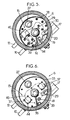
- the metal plates 32.33 are stressed upwards against the upper wall 30 of the housing by a leaf spring 36 (see Figure 3), with interposition resistive heating elements 37 between the two plates 32,33, these resistive elements 37 belonging to the electric heater 18 and preferably being of "PTC" type, that is to say with a positive temperature coefficient.
- the heating elements 37 are thus in contact thermal with metal plates 32.33. advantageously, these plates 32,33 are further connected to the connector electric 17 by electrodes or wires (not shown), so as to ensure the power supply heating elements 37.
- the top wall 30 of the housing is pierced with an orifice which forms the second outlet channel 14 of the thermostatic valve 9, and the underside of this wall 30 further carries the aforementioned thermal control switch 19.
- the underside of the wall 30 includes studs 38 projecting downwards, and a radial partition 39 which extends between the vertical shaft 29 and the side wall 34 of the housing 20, in the vicinity of the second outlet channel 14 of the thermostatic valve.
- This metal plate 33 is split radially, so as to fit on the partition 39, and said plate 33 is based on the aforementioned pads 38, thus being kept away from the wall 30 of the housing.
- the wall 33 itself forms oriented pads 44 down, and it is in contact with the elements heaters 37 above.
- the metal plate 32 is kept apart from the plate 31 by the aforementioned leaf spring 36, which stresses this plate 32 against the heating elements 37 and the pads 44 of the plate 33.
- the plate 31 can advantageously include a radial partition 43 shown in section in FIG. 7, which is arranged between the above-mentioned orifice 42 and the orifice 35 of the plate 31 so that the stream 40 of diesel go around the well 29.
- the diesel which passes in the recirculation loop 15 follows a relatively long path in traversing the three stages of said recirculation loop 15 parallel to the plates 32.33, which allows effectively reheat it in contact with the heating elements 37 and metal plates 32.33.
Landscapes
- Engineering & Computer Science (AREA)
- Chemical & Material Sciences (AREA)
- Combustion & Propulsion (AREA)
- Mechanical Engineering (AREA)
- General Engineering & Computer Science (AREA)
- Chemical Kinetics & Catalysis (AREA)
- Processes For Solid Components From Exhaust (AREA)
- Filtration Of Liquid (AREA)
- Lubrication Details And Ventilation Of Internal Combustion Engines (AREA)
Claims (8)
- Vorrichtung zur Gasölzuführung für Dieselmotoren, die aufweist:und einen Rückführkreis (7), der dazu geeignet, das überschüssige Gasöl stromabwärts von der Pumpe (4) aufzunehmen, wobei dieser Rückführkreis ein Thermostatventil (9) mit drei Wegen aufweist, das einen Einlassweg (10) und einen ersten und zweiten Auslassweg (12, 14) hat, wobei der Einlassweg (10) verbunden ist, um das überschüssige Gasöl stromabwärts von der Pumpe aufzunehmen, wobei der erste Auslassweg (12) mit dem Behälter (1) verbunden ist und der zweite Auslassweg (14) mit einen Rezirkulationskreis (15) in Verbindung steht, der mit dem Speisekreis (3) vor dem Filterelement (5) verbunden ist, wobei das Thermostatventil (9) dazu geeignet ist, das überschüssige Gasöl mehrheitlich zum ersten Auslassweg (12) auszurichten, wenn die Gasöltemperatur höher als eine vorbestimmte Temperatur ist, und das überschüssige Gasöl mehrheitlich zum zweiten Auslassweg (14) auszurichten, wenn die Gasöltemperatur niedriger als die vorbestimmte Temperatur ist, wobei der Rezirkulationskreis (15) nur durch überschüssiges Gasöl, das vom zweiten Auslassweg (14) des Thermostatventils (9) herstammt, durchlaufen wird,einen Gasölbehälter (1),eine Gasöleinspritzvorrichtung (2),einen Speisekreis (3), der den Behälter (1) mit der Einspritzvorrichtung (2) verbindet, wobei der Speisekreis einerseits eine Pumpe (4) aufweist, die die Einspritzvorrichtung speist, und andererseits ein Filterelement (5) aufweist, das sich vor der Pumpe befindet,
dadurch gekennzeichnet, dass der Rezirkulationskreis (15) eine elektrische Vorrichtung (16) zur Erwärmung des Gasöls aufweist. - Vorrichtung nach Anspruch 1, wobei das Filterelement (5) in einem Behältnis (21) enthalten ist, das durch ein Filtergehäuse (20) begrenzt wird, wobei das Gehäuse ebenfalls das Thermostatventil (9) und den Rezirkulationskreis (15) mit seiner elektrischen Heizeinrichtung (16) aufweist.
- Vorrichtung nach Anspruch 2, wobei das Filtergehäuse (20) ferner einen ersten Einlassanschluss (26), der mit dem Behälter (3) vor dem Filterelement (5) verbunden ist, einen ersten Auslassanschluss (28), der mit der Pumpe (4) stromabwärts von dem Filterelement verbunden ist, einen zweiten Einlassanschluss (10), der den Einlassweg des Thermostatventils bildet, und einen zweiten Auslassanschluss (12), der den ersten Auslassweg des Thermostatventils bildet, aufweist.
- Gasölfilter für eine Zuführvorrichtung nach Anspruch 2, der ein Filtergehäuse (20) aufweist, das ein ein Filterelement (5) enthaltendes Behältnis (21) begrenzt, wobei das Filtergehäuse ebenfalls aufweist:einen ersten Einlassanschluss (26), der mit dem Behältnis (21) vor dem Filterelement in Verbindung steht,einen ersten Auslassanschluss (28), der mit dem Behältnis (21) stromabwärts vom Filterelement in Verbindung steht,ein Thermostatventil (9) mit drei Wegen mit einem Einlassweg (10) und einem ersten und zweiten Auslassweg (12, 14), wobei der Einlassweg (10) durch einen zweiten Einlassanschluss gebildet ist, wobei der erste Auslassweg (12) durch einen zweiten Auslassanschluss gebildet wird, wobei das Thermostatventil (9) dazu geeignet ist, einen Gasölstrom vom Einlassweg (10) zum ersten Auslassweg (12) mehrheitlich auszurichten, wenn eine Temperatur des Gasöls höher als eine vorbestimmte Temperatur ist, und den Gasölstrom zum zweiten Auslassweg (14) mehrheitlich auszurichten, wenn die Gasöltemperatur niedriger als die vorbestimmte Temperatur ist,und einen Rezirkulationskreis (15) der den zweiten Auslassweg (14) des Thermostatventils mit dem Behältnis (21) vor dem Filterelement (5) verbindet, wobei der Rezirkulationskreis eine elektrische Vorrichtung (16) zur Erwärmung des Gasöls aufweist.
- Filter nach Anspruch 4, wobei der Rezirkulationskreis (15) zwischen einerseits einer Außenwand (30), die zum Filtergehäuse gehört, und andrerseits einer ersten angebrachten Platte (31), die sich im Behältnis (21) befindet, begrenzt wird, wobei die Außenwand und die erste angebrachte Platte von zwei Leitungen (27, 29) abgedichtet durchquert werden, die mit dem ersten Einlassanschluss (26) bzw. dem ersten Auslassanschluss (28) verbunden sind.
- Filter nach Anspruch 5, wobei der Rezirkulationskreis (15) drei übereinander angeordneten Stufen aufweist, die durch eine zweite und dritte angebrachte Metallplatte (32, 33) voneinander getrennt sind, die sich zwischen der Außenwand (30) des Gehäuses und der ersten angebrachten Platte (31) befinden und die mit den zur elektrischen Heizvorrichtung (16) gehörenden Heizelementen (37) in Wärmeberührung stehen, wobei der Rezirkulationskreis (15) in einer solchen Weise ausgebildet ist, dass das Gasöl, das diesen Rezirkulationskreis durchläuft, parallel zur zweiten und dritten angebrachten Platte (32, 33) in jeder Stufe des Rezirkulationskreises verläuft.
- Filter nach Anspruch 6, wobei die Heizelemente (37) zwischen die zweite und dritte angebrachte Platte (32, 33) die gegeneinander elastisch beansprucht sind, gedrückt sind.
- Filter nach Anspruch 7, wobei die Heizelemente (37) mittels der zweiten und dritten angebrachten Platte elektrisch gespeist sind.
Applications Claiming Priority (2)
| Application Number | Priority Date | Filing Date | Title |
|---|---|---|---|
| FR9810905 | 1998-09-01 | ||
| FR9810905A FR2782750B1 (fr) | 1998-09-01 | 1998-09-01 | Dispositif d'alimentation en gazole pour moteur diesel, et filtre pour un tel dispositif |
Publications (2)
| Publication Number | Publication Date |
|---|---|
| EP0984157A1 EP0984157A1 (de) | 2000-03-08 |
| EP0984157B1 true EP0984157B1 (de) | 2003-07-23 |
Family
ID=9530015
Family Applications (1)
| Application Number | Title | Priority Date | Filing Date |
|---|---|---|---|
| EP99402157A Expired - Lifetime EP0984157B1 (de) | 1998-09-01 | 1999-08-31 | Brennstoffzufuhrvorrichtung für Dieselmotor und Filter dafür |
Country Status (4)
| Country | Link |
|---|---|
| EP (1) | EP0984157B1 (de) |
| DE (1) | DE69909693T2 (de) |
| ES (1) | ES2204085T3 (de) |
| FR (1) | FR2782750B1 (de) |
Families Citing this family (12)
| Publication number | Priority date | Publication date | Assignee | Title |
|---|---|---|---|---|
| DE10030324A1 (de) * | 2000-06-27 | 2002-01-10 | Mann & Hummel Filter | Flüssigkeitskreislauf |
| FR2813807B1 (fr) * | 2000-09-14 | 2002-11-15 | Filtrauto | Filtre a gazole incluant un circuit electrique et dispositif de filtration comportant un tel filtre |
| DE10156408B4 (de) * | 2001-11-16 | 2014-01-09 | Robert Bosch Gmbh | Kraftstoffeinspritzeinrichtung für eine Brennkraftmaschine |
| DE10261690A1 (de) * | 2002-12-31 | 2004-07-15 | Robert Bosch Gmbh | Hochleistungs-Kraftstofffilter |
| WO2008000462A1 (de) | 2006-06-27 | 2008-01-03 | Georg Gruber | Dieselmotorisch betriebene brennkraftmaschine |
| EP2518301B1 (de) * | 2011-04-27 | 2013-09-04 | sigmar S.r.l. | Kraftstofffilterkopf mit integriertem Heizelement |
| JP6187526B2 (ja) * | 2015-04-07 | 2017-08-30 | トヨタ自動車株式会社 | 内燃機関の燃料供給装置 |
| ES2673611T3 (es) * | 2016-02-16 | 2018-06-25 | Willibrord Lösing Filterproduktion Gmbh | Dispositivo para la limpieza de un elemento líquido |
| CN106884750A (zh) * | 2017-03-28 | 2017-06-23 | 浙江嘉隆机械设备有限公司 | 在线检测自控式滤油机 |
| CN108590904B (zh) * | 2018-04-24 | 2020-12-15 | 南京汽车集团有限公司 | 一种柴油机低压燃油供给系统 |
| CN109184975B (zh) * | 2018-10-31 | 2024-03-22 | 东风富士汤姆森调温器有限公司 | 一种燃油温控阀及车辆燃油温控系统 |
| CN114508433B (zh) * | 2022-02-16 | 2022-10-28 | 一汽解放汽车有限公司 | 一种燃油供给系统的控制方法 |
Family Cites Families (10)
| Publication number | Priority date | Publication date | Assignee | Title |
|---|---|---|---|---|
| DE2715587C2 (de) * | 1977-04-07 | 1986-07-03 | Robert Bosch Gmbh, 7000 Stuttgart | Kraftstoffversorgungseinrichtung für Brennkraftmaschinen |
| IT1156963B (it) * | 1978-04-17 | 1987-02-04 | Fiat Veicoli Ind | Sistema per l'alimentazione del combustibile ad un motore a combustione interna |
| FR2490733A2 (fr) * | 1979-05-08 | 1982-03-26 | Elf France | Dispositif ameliorant le fonctionnement des moteurs diesel a basse temperature |
| JPS59224463A (ja) * | 1983-05-27 | 1984-12-17 | フオ−ド・モ−タ−・カンパニ− | デイ−ゼルエンジン用燃料フイルタ−装置 |
| DE3345391C2 (de) * | 1983-12-15 | 1994-05-26 | Bosch Gmbh Robert | Einrichtung zur temperaturabhängigen Umschaltung der Überströmmenge einer Diesel-Einspritzpumpe |
| DE3422979A1 (de) * | 1984-06-22 | 1986-01-02 | Robert Bosch Gmbh, 7000 Stuttgart | Filter fuer dieselkraftstoff |
| DE3717342C1 (en) * | 1987-05-22 | 1988-06-30 | Daimler Benz Ag | Low-pressure fuel circuit for an injection-type internal combustion engine with air compression |
| DE3825470A1 (de) * | 1988-07-27 | 1990-02-01 | Daimler Benz Ag | Fuer eine brennkraftmaschine vorgesehene kraftstoffversorgungseinrichtung |
| DE3923369C1 (en) * | 1989-07-14 | 1990-08-30 | Daimler-Benz Aktiengesellschaft, 7000 Stuttgart, De | Fuel supply unit for IC engine - has control valve taking fuel from return line to supply line if fuel temp. and pressure simultaneously fall below thresholds |
| FR2751242B1 (fr) * | 1996-07-18 | 1998-09-25 | Filtrauto | Filtre a gazole pour moteur diesel et dispositif d'alimentation incluant un tel filtre |
-
1998
- 1998-09-01 FR FR9810905A patent/FR2782750B1/fr not_active Expired - Fee Related
-
1999
- 1999-08-31 ES ES99402157T patent/ES2204085T3/es not_active Expired - Lifetime
- 1999-08-31 EP EP99402157A patent/EP0984157B1/de not_active Expired - Lifetime
- 1999-08-31 DE DE69909693T patent/DE69909693T2/de not_active Expired - Fee Related
Also Published As
| Publication number | Publication date |
|---|---|
| EP0984157A1 (de) | 2000-03-08 |
| DE69909693T2 (de) | 2004-04-15 |
| FR2782750B1 (fr) | 2000-10-20 |
| DE69909693D1 (de) | 2003-08-28 |
| FR2782750A1 (fr) | 2000-03-03 |
| ES2204085T3 (es) | 2004-04-16 |
Similar Documents
| Publication | Publication Date | Title |
|---|---|---|
| EP0984157B1 (de) | Brennstoffzufuhrvorrichtung für Dieselmotor und Filter dafür | |
| EP0819458B1 (de) | Kraftstoffilter für Dieselmotor und Zuführvorrichtung mit solchem Filter | |
| EP2052766B1 (de) | Flüssigkeitsfiltersystem mit Vorwärmung | |
| WO2017129896A1 (fr) | Filtre à carburant et support de montage dont la sortie est obturée par un clapet en cas de retrait d'un insert filtrant | |
| FR2950844A1 (fr) | Dispositif d'acheminement de liquide de nettoyage pour vehicule automobile | |
| FR2579678A1 (fr) | Dispositif d'alimentation en carburant | |
| FR2629875A1 (fr) | Separateur de vapeur | |
| FR2743849A1 (fr) | Module d'alimentation en carburant pour vehicule automobile | |
| EP0120733A1 (de) | Vorrichtung zur Brennstoffvorwärmung eines Dieselmotors | |
| FR2730459A1 (fr) | Dispositif pour transferer du carburant d'un reservoir a un moteur a combustion interne d'un vehicule automobile | |
| EP1188468B1 (de) | Flüssigkeitsfilter für Dieselkraftstoff mit einem elektrischen Stromkreis und Filtervorrichtung mit solchem Filter | |
| FR2915185A1 (fr) | Module pour reservoir a uree. | |
| EP1017937A1 (de) | Pumpvorrichtung für dieselkraftstoff eines kraftfahrzeuges | |
| FR2560406A1 (fr) | Thermostat pour le circuit de refroidissement du moteur d'un vehicule automobile | |
| FR2868331A1 (fr) | Systeme de filtration de liquide comprenant des moyens de chauffage de liquide | |
| FR2661489A1 (fr) | Dispositif de boite a eau et de vase d'expansion pour un echangeur de chaleur, tel qu'un radiateur de refroidissement, et echangeur de chaleur comprenant ce dispositif. | |
| FR2609111A1 (fr) | Dispositif de chauffage de carburant pour moteurs diesel | |
| FR2844461A1 (fr) | Filtre a gazole comportant un detecteur d'eau | |
| FR2589200A1 (fr) | Circuit d'alimentation en combustible avec prechauffage du carburant commande par thermostat pour un moteur a combustion interne a injection avec compression d'air | |
| FR2938881A1 (fr) | Filtre a carburant immerge dans un reservoir | |
| FR2640364A1 (fr) | Dispositif de boite a eau et de vase d'expansion pour echangeur de chaleur, en particulier pour radiateur de refroidissement | |
| FR2636903A1 (fr) | Dispositif de chauffage du liquide de lavage de vitres d'un vehicule automobile | |
| EP0371841B1 (de) | Kühlkreis einer Brennkraftmaschine eines Kraftwagens | |
| FR2621959A1 (fr) | Systeme modulaire de rechauffage, filtrage et decantation de carburant, notamment gazole | |
| FR2756324A1 (fr) | Filtre a carburant |
Legal Events
| Date | Code | Title | Description |
|---|---|---|---|
| PUAI | Public reference made under article 153(3) epc to a published international application that has entered the european phase |
Free format text: ORIGINAL CODE: 0009012 |
|
| AK | Designated contracting states |
Kind code of ref document: A1 Designated state(s): DE ES FR GB IT NL SE |
|
| AX | Request for extension of the european patent |
Free format text: AL;LT;LV;MK;RO;SI |
|
| 17P | Request for examination filed |
Effective date: 20000210 |
|
| AKX | Designation fees paid |
Free format text: DE ES FR GB IT NL SE |
|
| 17Q | First examination report despatched |
Effective date: 20020528 |
|
| GRAH | Despatch of communication of intention to grant a patent |
Free format text: ORIGINAL CODE: EPIDOS IGRA |
|
| GRAH | Despatch of communication of intention to grant a patent |
Free format text: ORIGINAL CODE: EPIDOS IGRA |
|
| GRAA | (expected) grant |
Free format text: ORIGINAL CODE: 0009210 |
|
| AK | Designated contracting states |
Designated state(s): DE ES FR GB IT NL SE |
|
| PG25 | Lapsed in a contracting state [announced via postgrant information from national office to epo] |
Ref country code: NL Free format text: LAPSE BECAUSE OF FAILURE TO SUBMIT A TRANSLATION OF THE DESCRIPTION OR TO PAY THE FEE WITHIN THE PRESCRIBED TIME-LIMIT Effective date: 20030723 |
|
| REG | Reference to a national code |
Ref country code: GB Ref legal event code: FG4D Free format text: NOT ENGLISH |
|
| PGFP | Annual fee paid to national office [announced via postgrant information from national office to epo] |
Ref country code: SE Payment date: 20030728 Year of fee payment: 5 Ref country code: NL Payment date: 20030728 Year of fee payment: 5 |
|
| GRAL | Information related to payment of fee for publishing/printing deleted |
Free format text: ORIGINAL CODE: EPIDOSDIGR3 |
|
| GRAS | Grant fee paid |
Free format text: ORIGINAL CODE: EPIDOSNIGR3 |
|
| REF | Corresponds to: |
Ref document number: 69909693 Country of ref document: DE Date of ref document: 20030828 Kind code of ref document: P |
|
| PG25 | Lapsed in a contracting state [announced via postgrant information from national office to epo] |
Ref country code: SE Free format text: LAPSE BECAUSE OF FAILURE TO SUBMIT A TRANSLATION OF THE DESCRIPTION OR TO PAY THE FEE WITHIN THE PRESCRIBED TIME-LIMIT Effective date: 20031023 |
|
| NLV1 | Nl: lapsed or annulled due to failure to fulfill the requirements of art. 29p and 29m of the patents act | ||
| GBT | Gb: translation of ep patent filed (gb section 77(6)(a)/1977) | ||
| REG | Reference to a national code |
Ref country code: ES Ref legal event code: FG2A Ref document number: 2204085 Country of ref document: ES Kind code of ref document: T3 |
|
| PLBE | No opposition filed within time limit |
Free format text: ORIGINAL CODE: 0009261 |
|
| STAA | Information on the status of an ep patent application or granted ep patent |
Free format text: STATUS: NO OPPOSITION FILED WITHIN TIME LIMIT |
|
| 26N | No opposition filed |
Effective date: 20040426 |
|
| PGFP | Annual fee paid to national office [announced via postgrant information from national office to epo] |
Ref country code: DE Payment date: 20040723 Year of fee payment: 6 |
|
| PGFP | Annual fee paid to national office [announced via postgrant information from national office to epo] |
Ref country code: GB Payment date: 20040728 Year of fee payment: 6 |
|
| PGFP | Annual fee paid to national office [announced via postgrant information from national office to epo] |
Ref country code: ES Payment date: 20040809 Year of fee payment: 6 |
|
| PG25 | Lapsed in a contracting state [announced via postgrant information from national office to epo] |
Ref country code: IT Free format text: LAPSE BECAUSE OF NON-PAYMENT OF DUE FEES;WARNING: LAPSES OF ITALIAN PATENTS WITH EFFECTIVE DATE BEFORE 2007 MAY HAVE OCCURRED AT ANY TIME BEFORE 2007. THE CORRECT EFFECTIVE DATE MAY BE DIFFERENT FROM THE ONE RECORDED. Effective date: 20050831 Ref country code: GB Free format text: LAPSE BECAUSE OF NON-PAYMENT OF DUE FEES Effective date: 20050831 |
|
| PG25 | Lapsed in a contracting state [announced via postgrant information from national office to epo] |
Ref country code: ES Free format text: LAPSE BECAUSE OF NON-PAYMENT OF DUE FEES Effective date: 20050901 |
|
| PG25 | Lapsed in a contracting state [announced via postgrant information from national office to epo] |
Ref country code: DE Free format text: LAPSE BECAUSE OF NON-PAYMENT OF DUE FEES Effective date: 20060301 |
|
| GBPC | Gb: european patent ceased through non-payment of renewal fee |
Effective date: 20050831 |
|
| REG | Reference to a national code |
Ref country code: ES Ref legal event code: FD2A Effective date: 20050901 |
|
| REG | Reference to a national code |
Ref country code: FR Ref legal event code: PLFP Year of fee payment: 17 |
|
| REG | Reference to a national code |
Ref country code: FR Ref legal event code: PLFP Year of fee payment: 18 |
|
| REG | Reference to a national code |
Ref country code: FR Ref legal event code: PLFP Year of fee payment: 19 |
|
| REG | Reference to a national code |
Ref country code: FR Ref legal event code: PLFP Year of fee payment: 20 |
|
| PGFP | Annual fee paid to national office [announced via postgrant information from national office to epo] |
Ref country code: FR Payment date: 20180720 Year of fee payment: 20 |