EP0120986A1 - Procédé pour la production de courant dans un processus de combustion cyclique - Google Patents
Procédé pour la production de courant dans un processus de combustion cyclique Download PDFInfo
- Publication number
- EP0120986A1 EP0120986A1 EP83103243A EP83103243A EP0120986A1 EP 0120986 A1 EP0120986 A1 EP 0120986A1 EP 83103243 A EP83103243 A EP 83103243A EP 83103243 A EP83103243 A EP 83103243A EP 0120986 A1 EP0120986 A1 EP 0120986A1
- Authority
- EP
- European Patent Office
- Prior art keywords
- piston
- combustion process
- coil
- piston system
- combustion
- Prior art date
- Legal status (The legal status is an assumption and is not a legal conclusion. Google has not performed a legal analysis and makes no representation as to the accuracy of the status listed.)
- Withdrawn
Links
- 238000002485 combustion reaction Methods 0.000 title claims abstract description 36
- 238000000034 method Methods 0.000 title claims abstract description 33
- 125000004122 cyclic group Chemical group 0.000 title claims description 5
- 230000006835 compression Effects 0.000 claims abstract description 13
- 238000007906 compression Methods 0.000 claims abstract description 13
- 230000003247 decreasing effect Effects 0.000 claims abstract description 5
- 239000000203 mixture Substances 0.000 claims abstract description 5
- 230000010355 oscillation Effects 0.000 claims description 12
- 238000010248 power generation Methods 0.000 claims description 5
- 230000009471 action Effects 0.000 claims description 2
- 230000003534 oscillatory effect Effects 0.000 claims description 2
- 230000001960 triggered effect Effects 0.000 claims 1
- 239000000446 fuel Substances 0.000 abstract description 9
- 238000010892 electric spark Methods 0.000 abstract 2
- 230000000694 effects Effects 0.000 abstract 1
- 230000004907 flux Effects 0.000 abstract 1
- 230000001939 inductive effect Effects 0.000 abstract 1
- 230000008569 process Effects 0.000 description 14
- 230000005611 electricity Effects 0.000 description 5
- 238000010304 firing Methods 0.000 description 4
- 239000000243 solution Substances 0.000 description 3
- TZCXTZWJZNENPQ-UHFFFAOYSA-L barium sulfate Chemical compound [Ba+2].[O-]S([O-])(=O)=O TZCXTZWJZNENPQ-UHFFFAOYSA-L 0.000 description 2
- 230000008901 benefit Effects 0.000 description 2
- 230000009467 reduction Effects 0.000 description 2
- 206010065929 Cardiovascular insufficiency Diseases 0.000 description 1
- 206010053615 Thermal burn Diseases 0.000 description 1
- 239000000872 buffer Substances 0.000 description 1
- 230000008859 change Effects 0.000 description 1
- 239000004020 conductor Substances 0.000 description 1
- 238000010276 construction Methods 0.000 description 1
- 238000001816 cooling Methods 0.000 description 1
- 238000010790 dilution Methods 0.000 description 1
- 239000012895 dilution Substances 0.000 description 1
- 230000005284 excitation Effects 0.000 description 1
- 239000002360 explosive Substances 0.000 description 1
- 239000002655 kraft paper Substances 0.000 description 1
- 238000005381 potential energy Methods 0.000 description 1
- 230000004044 response Effects 0.000 description 1
- 231100000331 toxic Toxicity 0.000 description 1
- 230000002588 toxic effect Effects 0.000 description 1
- 239000002699 waste material Substances 0.000 description 1
- 238000004804 winding Methods 0.000 description 1
Images
Classifications
-
- H—ELECTRICITY
- H02—GENERATION; CONVERSION OR DISTRIBUTION OF ELECTRIC POWER
- H02K—DYNAMO-ELECTRIC MACHINES
- H02K7/00—Arrangements for handling mechanical energy structurally associated with dynamo-electric machines, e.g. structural association with mechanical driving motors or auxiliary dynamo-electric machines
- H02K7/18—Structural association of electric generators with mechanical driving motors, e.g. with turbines
- H02K7/1869—Linear generators; sectional generators
- H02K7/1876—Linear generators; sectional generators with reciprocating, linearly oscillating or vibrating parts
- H02K7/1884—Linear generators; sectional generators with reciprocating, linearly oscillating or vibrating parts structurally associated with free piston engines
Definitions
- the invention relates to a method for power generation in a cyclic combustion process, in which mechanical linear reciprocating movements of a piston system consisting of two inseparably coupled pistons in two opposite combustion chambers are produced, the combustion chambers successively and cyclically repeating one another an electrical spark initiated burning process takes place, and the kinetic energy of the reciprocating movements of the moving parts is converted into electrical energy.
- Cyclic V are erbrennungsvone onset method is known wherein mechanical vibrations are generated, which are in turn converted into electrical energy.
- So-called gas generators are used in practice. This is shaftless piston V erbrennungs- motors with high power, to drive the compressor. A high-speed gas turbine coupled to an electric rotation generator is then supplied by the compressor to generate electricity.
- these engines work with a limited degree of compression, which results in low efficiency.
- Such engines are not equipped with a flywheel, so they do not store the energy of the previous cycles for the subsequent cycles and have a low vibration frequency in the order of 20 Hz, regardless of the fact that they are operated with low vibration masses.
- the compressed gas that dissipates energy is practically inert.
- the compression required to run a diesel cycle is generated by additional air buffers. This type of piston internal combustion engine requires additional synchronization and starting devices.
- the coil is advantageously automatically switched from generator to motor operation, and from normal to engine operation when the normal operating conditions are restored.
- the process according to the invention has the advantage that operation at a high frequency of the piston system is possible - even above 125 Hz, with frequencies of the order of 300 Hz being possible with a normal piston stroke - at high linear speeds of approximately 20 m / s, which is comparable to the speed of flame propagation in the combustion chambers.
- high pressures are obtained at the end of the piston stroke, which result in a degree of compression which is higher than that which is characteristic of the diesel process and is of the order of more than 25. This leads to a high thermal efficiency.
- the high linear speed of the vibrations reduces the losses due to cooling through the cylinder walls. Ignition at low compression levels and burning with decreasing volume extend the burning time and allow more complete burning of the fuel.
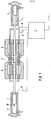
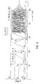
- the speed of the piston system 1, 2 not only increases rapidly as an average. It remains constant or approximately constant, namely during the entire stroke of pistons 1 and 2 to the end points and back (FIG. 2).
- the increase in the oscillation speed leads to a corresponding increase in the counter electromotive force in the coil 5 and to a gradual decrease in the current intensity. After the current intensity reaches the zero value, the current changes its direction and the coil 5 is switched over by the control unit 7 to generator operation.
- the load on the generator 5, 6 gradually increases and reaches its nominal value at a preselected oscillation speed corresponding to a certain generated voltage. While reaching the At the nominal value of the generator output, the piston system is accelerated primarily due to the increase in the reactive compression output.
- the constant operating conditions occur when the derived electrical energy reaches the value of that obtained by the V erbrennungslui kinetic energy and the 'vibrational speed the preselected value.
- the electrical voltage generated has a frequency which is the same as the oscillation frequency of the coil 5. Due to the high oscillation frequency of the coil 5, which has a low weight, an increase in the electrical losses when harmonic frequencies occur is avoided.
- control unit 7 Should the oscillation speed fall below a certain limit for some reason, for example in the event of faults in the combustion process or overloads, the control unit 7 generates pulses again and the coil 5 temporarily switches over to motor operation. Switching the coil 5 from motor to generator operation and vice versa, as well as storing energy from the previous cycles for the subsequent ones, stabilizes the frequency and plays the role of a flywheel without mass.
- the safest way to switch off the device is to interrupt the fuel supply.
Landscapes
- Engineering & Computer Science (AREA)
- Power Engineering (AREA)
- Connection Of Motors, Electrical Generators, Mechanical Devices, And The Like (AREA)
Priority Applications (1)
| Application Number | Priority Date | Filing Date | Title |
|---|---|---|---|
| EP83103243A EP0120986A1 (fr) | 1983-03-31 | 1983-03-31 | Procédé pour la production de courant dans un processus de combustion cyclique |
Applications Claiming Priority (1)
| Application Number | Priority Date | Filing Date | Title |
|---|---|---|---|
| EP83103243A EP0120986A1 (fr) | 1983-03-31 | 1983-03-31 | Procédé pour la production de courant dans un processus de combustion cyclique |
Publications (1)
| Publication Number | Publication Date |
|---|---|
| EP0120986A1 true EP0120986A1 (fr) | 1984-10-10 |
Family
ID=8190388
Family Applications (1)
| Application Number | Title | Priority Date | Filing Date |
|---|---|---|---|
| EP83103243A Withdrawn EP0120986A1 (fr) | 1983-03-31 | 1983-03-31 | Procédé pour la production de courant dans un processus de combustion cyclique |
Country Status (1)
| Country | Link |
|---|---|
| EP (1) | EP0120986A1 (fr) |
Cited By (5)
| Publication number | Priority date | Publication date | Assignee | Title |
|---|---|---|---|---|
| DE4344915A1 (de) * | 1993-12-29 | 1995-07-06 | Jakob Hilt | Linearverbrennungsmotorgenerator |
| WO1998004819A1 (fr) | 1996-07-30 | 1998-02-05 | Rinaldo Lampis | Groupe generateur lineaire a haut rendement, procede de controle et unite de traction associee |
| DE19738375A1 (de) * | 1997-09-03 | 1999-03-18 | Toni Sutor | Zweitaktfreikolbenmotorbetriebener Linearstromgenerator |
| WO2001078219A1 (fr) * | 2000-04-07 | 2001-10-18 | Abb Ab | Machine electrique |
| WO2001045977A3 (fr) * | 1999-12-22 | 2001-11-15 | Abb Ab | Dispositif comprenant un moteur a combustion, utilisation de ce dispositif, et vehicule |
Citations (5)
| Publication number | Priority date | Publication date | Assignee | Title |
|---|---|---|---|---|
| DD30765A (fr) * | ||||
| US3247406A (en) * | 1961-10-03 | 1966-04-19 | Toesca Rene Antoine Michel | Electromechanical energy converting device |
| DE2355728A1 (de) * | 1973-11-08 | 1975-05-15 | Gerhard Noeltner | Motorgenerator |
| DE2654629A1 (de) * | 1976-12-02 | 1978-06-08 | Georg Sontheimer | Pendelkolbenmotor in verbindung mit einer einrichtung zur erzeugung elektrischer spannungen und stroeme |
| DE3139357A1 (de) * | 1981-10-02 | 1983-04-21 | Zuv "Progress", Sofija | Verfahren fuer die stromerzeugung bei einem zyklischen verbrennungsprozess |
-
1983
- 1983-03-31 EP EP83103243A patent/EP0120986A1/fr not_active Withdrawn
Patent Citations (5)
| Publication number | Priority date | Publication date | Assignee | Title |
|---|---|---|---|---|
| DD30765A (fr) * | ||||
| US3247406A (en) * | 1961-10-03 | 1966-04-19 | Toesca Rene Antoine Michel | Electromechanical energy converting device |
| DE2355728A1 (de) * | 1973-11-08 | 1975-05-15 | Gerhard Noeltner | Motorgenerator |
| DE2654629A1 (de) * | 1976-12-02 | 1978-06-08 | Georg Sontheimer | Pendelkolbenmotor in verbindung mit einer einrichtung zur erzeugung elektrischer spannungen und stroeme |
| DE3139357A1 (de) * | 1981-10-02 | 1983-04-21 | Zuv "Progress", Sofija | Verfahren fuer die stromerzeugung bei einem zyklischen verbrennungsprozess |
Cited By (14)
| Publication number | Priority date | Publication date | Assignee | Title |
|---|---|---|---|---|
| DE4344915A1 (de) * | 1993-12-29 | 1995-07-06 | Jakob Hilt | Linearverbrennungsmotorgenerator |
| WO1998004819A1 (fr) | 1996-07-30 | 1998-02-05 | Rinaldo Lampis | Groupe generateur lineaire a haut rendement, procede de controle et unite de traction associee |
| DE19738375A1 (de) * | 1997-09-03 | 1999-03-18 | Toni Sutor | Zweitaktfreikolbenmotorbetriebener Linearstromgenerator |
| DE19738375C2 (de) * | 1997-09-03 | 1999-07-08 | Toni Sutor | Zweitaktfreikolbenmotorbetriebener Linearstromgenerator |
| WO2001045977A3 (fr) * | 1999-12-22 | 2001-11-15 | Abb Ab | Dispositif comprenant un moteur a combustion, utilisation de ce dispositif, et vehicule |
| US6748907B2 (en) | 1999-12-22 | 2004-06-15 | Abb Ab | Device including a combustion engine, a use of the device, and a vehicle |
| AU778457B2 (en) * | 1999-12-22 | 2004-12-09 | Volvo Technology Ab | A device including a combustion engine, a use of the device, and a vehicle |
| KR100809893B1 (ko) | 1999-12-22 | 2008-03-07 | 볼보 테크놀로지 악티에볼라그 | 연소기관을 포함하는 장치 및 이 장치를 구비한 차량 |
| WO2001078218A1 (fr) * | 2000-04-07 | 2001-10-18 | Abb Ab | Machine electrique |
| WO2001078219A1 (fr) * | 2000-04-07 | 2001-10-18 | Abb Ab | Machine electrique |
| JP2004500800A (ja) * | 2000-04-07 | 2004-01-08 | エービービー アクチボラゲット | 電気機械 |
| US6700229B2 (en) | 2000-04-07 | 2004-03-02 | Abb Ab | Electrical machine |
| US6717297B2 (en) | 2000-04-07 | 2004-04-06 | Abb Ab | Electrical machine |
| AU2001247013B2 (en) * | 2000-04-07 | 2005-06-30 | Volvo Technology Ab | An electrical machine |
Similar Documents
| Publication | Publication Date | Title |
|---|---|---|
| DE3139357C2 (de) | Verfahren für die Stromerzeugung bei einem zyklischen Verbrennungsprozeß | |
| DE3913806C2 (de) | Hybridmotor | |
| DE60116598T2 (de) | Energieumwandler | |
| DE69017386T2 (de) | Maschine mit magnetischem Schwungrad. | |
| US4154200A (en) | Non-polluting heat machine with internal combustion | |
| DE2352336A1 (de) | Elektrischer generator, insbesondere fuer verbrennungsmaschinen | |
| EP1534944A1 (fr) | Procede pour reguler le fonctionnement d'un dispositif pour la generation d'energie electrique au moyen d'un generateur entraine par un moteur a combustion interne a piston libre | |
| DE2624283C2 (de) | Wechselstromerzeuger mit Impulserregung | |
| DE3103432A1 (de) | Lineare verbrennungskraftmaschine, die mit einem elektrischen lineargenerator eine baueinheit bildet | |
| AT508410A1 (de) | Schwingungskompensierter freikolbenmotor | |
| WO2021204314A1 (fr) | Système de production d'énergie et procédé de régulation de la vitesse de rotation d'une unité d'entraînement dans un système de production d'énergie | |
| EP0120986A1 (fr) | Procédé pour la production de courant dans un processus de combustion cyclique | |
| DE2355728A1 (de) | Motorgenerator | |
| DE4315046A1 (de) | Freikolbenmotor und Verfahren zur Umwandlung von in Kraftstoff gespeicherter Energie in elektrische Energie bei einem Freikolbenmotor | |
| DE597089C (de) | Zweitakt-Dieselmaschine mit einer von den Maschinenabgasen beaufschlagten Abgasturbine und einem Spuel- und Ladeverdichter | |
| DE102010026889B4 (de) | Systeme für Freikolbenlineargeneratoren | |
| DE102011087790B4 (de) | Vorrichtung und Verfahren zur Stromerzeugung | |
| DE4133948C2 (de) | Freikolbenmotor | |
| DE102014001770A1 (de) | Verbrennungskraftmaschine mit linearer elektrischer Führung | |
| DE3617365A1 (de) | Verfahren und vorrichtung zum antreiben einer welle | |
| DE102011101018B4 (de) | Verbrennungsmotor-Antriebseinheit mit mechanisch-elektrischer Direktumwandlung bei oszillierendem Antrieb | |
| WO1999001649A1 (fr) | Procede d'amelioration du rendement global d'un groupe moteur hybride | |
| DE102017115171B4 (de) | Freikolbenvorrichtung und Verfahren zum Betreiben einer Freikolbenvorrichtung | |
| CH118540A (de) | Kraftanlage. | |
| DE431648C (de) | Kraftanlage mit Flugkolbenmotor |
Legal Events
| Date | Code | Title | Description |
|---|---|---|---|
| PUAI | Public reference made under article 153(3) epc to a published international application that has entered the european phase |
Free format text: ORIGINAL CODE: 0009012 |
|
| AK | Designated contracting states |
Kind code of ref document: A1 Designated state(s): BE CH DE FR GB IT LI SE |
|
| 17P | Request for examination filed |
Effective date: 19850226 |
|
| STAA | Information on the status of an ep patent application or granted ep patent |
Free format text: STATUS: THE APPLICATION IS DEEMED TO BE WITHDRAWN |
|
| 18D | Application deemed to be withdrawn |
Effective date: 19860421 |
|
| RIN1 | Information on inventor provided before grant (corrected) |
Inventor name: MAKEDONSKI, FREDERIK MAXIMOV, DIPL.-ING. Inventor name: KARAMANSKI, STEFAN DIMITROV, DIPL.-ING. Inventor name: KERVANBASCHIEV, STOJU STOEV, DIPL.-ING. Inventor name: ILIEV, MAXIM DIMITROV, DIPL.-ING. |