EP0121063A1 - Entraînement en rotation réglable sans jeu d'au moins un arbre principal pour manipulateurs - Google Patents
Entraînement en rotation réglable sans jeu d'au moins un arbre principal pour manipulateurs Download PDFInfo
- Publication number
- EP0121063A1 EP0121063A1 EP84101542A EP84101542A EP0121063A1 EP 0121063 A1 EP0121063 A1 EP 0121063A1 EP 84101542 A EP84101542 A EP 84101542A EP 84101542 A EP84101542 A EP 84101542A EP 0121063 A1 EP0121063 A1 EP 0121063A1
- Authority
- EP
- European Patent Office
- Prior art keywords
- gear
- drive
- shaft
- axis
- wheel
- Prior art date
- Legal status (The legal status is an assumption and is not a legal conclusion. Google has not performed a legal analysis and makes no representation as to the accuracy of the status listed.)
- Granted
Links
Images


Classifications
-
- B—PERFORMING OPERATIONS; TRANSPORTING
- B25—HAND TOOLS; PORTABLE POWER-DRIVEN TOOLS; MANIPULATORS
- B25J—MANIPULATORS; CHAMBERS PROVIDED WITH MANIPULATION DEVICES
- B25J17/00—Joints
- B25J17/02—Wrist joints
- B25J17/0241—One-dimensional joints
-
- B—PERFORMING OPERATIONS; TRANSPORTING
- B25—HAND TOOLS; PORTABLE POWER-DRIVEN TOOLS; MANIPULATORS
- B25J—MANIPULATORS; CHAMBERS PROVIDED WITH MANIPULATION DEVICES
- B25J9/00—Program-controlled manipulators
- B25J9/10—Program-controlled manipulators characterised by positioning means for manipulator elements
- B25J9/102—Gears specially adapted therefor, e.g. reduction gears
- B25J9/103—Gears specially adapted therefor, e.g. reduction gears with backlash-preventing means
-
- Y—GENERAL TAGGING OF NEW TECHNOLOGICAL DEVELOPMENTS; GENERAL TAGGING OF CROSS-SECTIONAL TECHNOLOGIES SPANNING OVER SEVERAL SECTIONS OF THE IPC; TECHNICAL SUBJECTS COVERED BY FORMER USPC CROSS-REFERENCE ART COLLECTIONS [XRACs] AND DIGESTS
- Y10—TECHNICAL SUBJECTS COVERED BY FORMER USPC
- Y10T—TECHNICAL SUBJECTS COVERED BY FORMER US CLASSIFICATION
- Y10T74/00—Machine element or mechanism
- Y10T74/18—Mechanical movements
- Y10T74/18568—Reciprocating or oscillating to or from alternating rotary
- Y10T74/18832—Reciprocating or oscillating to or from alternating rotary including flexible drive connector [e.g., belt, chain, strand, etc.]
-
- Y—GENERAL TAGGING OF NEW TECHNOLOGICAL DEVELOPMENTS; GENERAL TAGGING OF CROSS-SECTIONAL TECHNOLOGIES SPANNING OVER SEVERAL SECTIONS OF THE IPC; TECHNICAL SUBJECTS COVERED BY FORMER USPC CROSS-REFERENCE ART COLLECTIONS [XRACs] AND DIGESTS
- Y10—TECHNICAL SUBJECTS COVERED BY FORMER USPC
- Y10T—TECHNICAL SUBJECTS COVERED BY FORMER US CLASSIFICATION
- Y10T74/00—Machine element or mechanism
- Y10T74/19—Gearing
- Y10T74/1987—Rotary bodies
- Y10T74/19893—Sectional
- Y10T74/19898—Backlash take-up
Definitions
- manipulators can only be used in practice if they can control the specified target with great accuracy.
- the known manipulators only fulfill this condition incompletely because the play present in the gears used is considerably translated due to the large radius of the cantilever, which means that the mechanical hand reaches its destination in a spreading range corresponding to this transmission ratio.
- This control inaccuracy is particularly noticeable when the part to be moved has to be moved in an oscillating manner, possibly even beyond the dead center of its swivel position.
- the invention is therefore based on the object to develop a play-free adjustment by torsional stresses and, by elastic deformation, a higher load-bearing portion of the torque-transmitting parts and their bearings, and thus to develop a more vibration-resistant rotary actuator, the efficiency of which is significantly increased and which enables faster control or regulation of the According to positioning processes, the natural frequency can be increased and compliance with an elastic symmetry in both directions of rotation is fully effective.
- a manipulator is known from DE-PS 22 26 407, in which individual stages of the swivel drives are formed by toothed belt gears.
- toothed belt gears At the time of the disclosure of this prior art, no backlash-free toothed belt gears were known. Their use was essentially the sense to overcome larger distances between the drive motor and the shaft to be driven in a structurally simple manner, and the engine speed to one for the subsequent switched gearbox to reduce compatible speed.
- the combination according to the invention not only achieves the stated object, but also achieves an unforeseeable combination effect, to which some features contribute in a way that has hitherto remained unknown.
- the last gear stage provided on the output side which is designed as a steel wheel gear, brings the advantage of high reduction in one step. If a toothed belt gear were to be used in its place, an additional gear stage would be necessary to generate the required reduction, because high-reduction and slow-running toothed belt gear units require a larger construction volume than steel wheel stages, which is impossible due to the limited space available.
- the spring constant C depends on the size of the natural frequency according to the formula has a direct effect, it is an essential determining factor for the vibration rigidity of the construction.
- the backlash-free steel gear stage is maintenance-free for months due to its low speed as the last gear stage due to lubrication with adhesive long-term grease. It saves an entire gear stage due to the largest possible reduction and gives the driven machine part an equally high natural vibration number due to its directly acting high natural frequency. It has been shown that torsional vibrations that occur during acceleration and deceleration of the drive processes subside faster, the greater the natural frequency of the machine part to be driven.
- the invention uses the advantages of toothed belt drives, such as freedom from maintenance and backlash, inexpensive construction, bridging longer distances between the driving and driven part, in places from which the vibration rigidity of the construction cannot be adversely affected. It is therefore advisable to design at least the drive-side gear stage as a backlash-free toothed belt gear ....
- the person skilled in the art is given greater freedom with regard to the choice between steel wheel stage or toothed belt stage. If you choose toothed belt gearboxes, this has a positive effect in terms of total costs and freedom from maintenance.
- the invention does not exclude the use of a further steel wheel transmission, preferably at the penultimate transmission stage.
- the backlash-free toothed belt transmissions used in the subject matter of the invention are known assemblies which are referred to in traffic as HTD (high torque drive). These are belts with rounded tooth profiles, which are highly efficient and whose wheels can be manufactured for play-free running.
- a so-called carousel 2 is pivotally mounted about a vertical axis of rotation 3 on a floor-fixed base frame 1.
- the carousel 2 is rotated about the pivot axis 3 by means of a drive motor 4, and the direction of rotation can be changed.
- a drive arm 5 is pivotally mounted in the pivot axis 6, the pivoting movement of which is generated by the drive motor 7.
- This pivot axis 6 is horizontal.
- the weight of the drive arm 5 and the parts arranged thereon is balanced by a schematically indicated weight compensation 8.
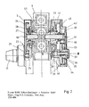
- the swivel gear shown in FIG. 2 is used in the exemplary embodiment to pivot the boom 9 about the swivel axis 10, for which purpose the drive motor 11 is used.
- the principle of the swivel drive shown in FIG. 2 can also be used for all or some of the other axes, in particular for the main axes 3 and 6 according to FIG. 1. It also goes without saying that such swivel drives according to the invention also for manipulators designed in another way can be used with advantage.
- the driven gear 33 of the second gear stage 30 shown in the exemplary embodiment is mounted in a bearing housing 34 via the bearing 35.
- a hub 36 connected to the driven gear 33 acts via a tensioning arrangement 37, which is described in detail in FIG. 3, on the third gear stage 38, which is designed as a steel gear, for example with spur gearing.
- the third gear stage 38 which is designed as a steel gear, for example with spur gearing.
- two pinion halves 39, 40 are provided which are torsionally braced to one another. They act on the driven gear 41, the hub 43 Is clamped to the bearing eye 57 of the bracket 9 via the screw connection 42. So that the driven wheel 41 is rotatably connected to the boom 9. Due to the high reduction of the steel stage 38 (third gear stage), which can be 1: 7, for example, a particularly high rigidity and thus natural frequency is created in the drive of the boom 9, with which a faster and more precise target control can be achieved.
- the pinion half 39 is connected to a torsionally elastic shaft 44 and the pinion half 40 is connected to a torsionally elastic sleeve 45, there being essentially a play 46 between the two parts 44, 45.
- the torsionally elastic sleeve 45 is guided in the region of the pinion half 40 assigned to it via the bearing point 54 on the torsionally elastic shaft 44.
- a direct bearing point 47 is provided between the torsionally elastic shaft 44 and the torsionally elastic sleeve 45.
Landscapes
- Engineering & Computer Science (AREA)
- Robotics (AREA)
- Mechanical Engineering (AREA)
- Gear Transmission (AREA)
- Manipulator (AREA)
- Transmission Devices (AREA)
- Control Of Position Or Direction (AREA)
- Coating By Spraying Or Casting (AREA)
- Gears, Cams (AREA)
Priority Applications (1)
| Application Number | Priority Date | Filing Date | Title |
|---|---|---|---|
| AT84101542T ATE25609T1 (de) | 1983-03-09 | 1984-02-15 | Spielfrei einstellbarer schwenkantrieb fuer mindestens eine hauptachse von manipulatoren. |
Applications Claiming Priority (2)
| Application Number | Priority Date | Filing Date | Title |
|---|---|---|---|
| DE3308413A DE3308413C1 (de) | 1983-03-09 | 1983-03-09 | Spielfrei einstellbarer Schwenkantrieb fuer mindestens eine Hauptachse von Manipulatoren |
| DE3308413 | 1983-03-09 |
Publications (2)
| Publication Number | Publication Date |
|---|---|
| EP0121063A1 true EP0121063A1 (fr) | 1984-10-10 |
| EP0121063B1 EP0121063B1 (fr) | 1987-03-04 |
Family
ID=6192995
Family Applications (1)
| Application Number | Title | Priority Date | Filing Date |
|---|---|---|---|
| EP84101542A Expired EP0121063B1 (fr) | 1983-03-09 | 1984-02-15 | Entraînement en rotation réglable sans jeu d'au moins un arbre principal pour manipulateurs |
Country Status (9)
| Country | Link |
|---|---|
| US (1) | US4741218A (fr) |
| EP (1) | EP0121063B1 (fr) |
| JP (1) | JPS59169791A (fr) |
| AT (1) | ATE25609T1 (fr) |
| AU (1) | AU567546B2 (fr) |
| DD (1) | DD217294A5 (fr) |
| DE (2) | DE3308413C1 (fr) |
| ES (1) | ES8503272A1 (fr) |
| SU (1) | SU1567129A3 (fr) |
Cited By (3)
| Publication number | Priority date | Publication date | Assignee | Title |
|---|---|---|---|---|
| EP0152936A1 (fr) * | 1984-02-21 | 1985-08-28 | EKE Robotersysteme GmbH | Entraînement rotatif mécanique |
| GB2215242A (en) * | 1988-02-24 | 1989-09-20 | Jobs Spa | A head for machine tools having devices for automatically taking up play |
| FR2657933A1 (fr) * | 1990-02-06 | 1991-08-09 | Peugeot | Dispositif de rattrapage de jeu sur un element tel qu'un poignet de robot. |
Families Citing this family (9)
| Publication number | Priority date | Publication date | Assignee | Title |
|---|---|---|---|---|
| JPS60161083A (ja) * | 1984-01-30 | 1985-08-22 | 三菱電機株式会社 | ア−ク溶接ロボツトの旋回軸バツクラツシユ補正装置 |
| DE3448409C2 (en) * | 1984-12-28 | 1993-01-28 | Kuka Schweissanlagen + Roboter Gmbh, 8900 Augsburg, De | Modular driving unit for industrial robot |
| AU584798B2 (en) * | 1986-03-25 | 1989-06-01 | Laser Lab Limited | Work head device |
| DE3777737D1 (de) * | 1986-03-25 | 1992-04-30 | Laser Lab Ltd | Anordnung mit arbeitskopf. |
| JPH0665903B2 (ja) * | 1987-03-12 | 1994-08-24 | 崇 高橋 | 制御用変速装置 |
| CN101246083B (zh) * | 2008-03-24 | 2010-06-02 | 西安电子科技大学 | 直齿圆柱齿轮动态啮合刚度的测量方法 |
| DE102021003318A1 (de) | 2021-06-29 | 2022-12-29 | Günther Zimmer | Industrieroboter mit kompakt aufgebautem Achsantrieb |
| CN116787489B (zh) * | 2023-05-26 | 2026-03-06 | 沈阳新松机器人自动化股份有限公司 | 一种安装位姿自适应型工业机器人关节润滑结构 |
| CN118046421B (zh) * | 2024-04-16 | 2024-06-21 | 以诺康医疗科技(苏州)有限公司 | 手术机器人关节实际力矩的自动采集方法及系统 |
Citations (1)
| Publication number | Priority date | Publication date | Assignee | Title |
|---|---|---|---|---|
| US3020775A (en) * | 1960-05-12 | 1962-02-13 | United Shoe Machinery Corp | Antibacklash devices |
Family Cites Families (9)
| Publication number | Priority date | Publication date | Assignee | Title |
|---|---|---|---|---|
| US2868033A (en) * | 1957-07-03 | 1959-01-13 | Raymond A Gaither | Torsion bar anti-backlash gear |
| US3037396A (en) * | 1959-05-11 | 1962-06-05 | Merrill David Martin | Backlash preventing gears for coupled driven and drive shafts |
| DE2226407C3 (de) * | 1972-05-31 | 1978-10-12 | Industrie-Werke Karlsruhe Augsburg Ag, 7500 Karlsruhe | Gerät zur maschinellen, durch veränderbare Programme steuerbaren Handreichung |
| SU560746A2 (ru) * | 1975-06-13 | 1977-06-05 | Московское Ордена Ленина И Ордена Трудового Красного Знамени Высшее Техническое Училище Им.Н.Э.Баумана | Исполнительный орган манипул тора |
| JPS5276070U (fr) * | 1975-12-04 | 1977-06-07 | ||
| US4072064A (en) * | 1977-02-02 | 1978-02-07 | Westinghouse Electric Corporation | Anti-backlash gear assembly |
| FR2483300A1 (fr) * | 1980-05-28 | 1981-12-04 | Expl Mat Indls Const | Manipulateur industriel perfectionne |
| DE3115061C2 (de) * | 1980-05-29 | 1985-05-30 | Kuka Schweissanlagen + Roboter Gmbh, 8900 Augsburg | Spielfreier Schwenkantrieb für schwenkbar gelagerte Bauteile |
| JPS576826U (fr) * | 1980-06-13 | 1982-01-13 |
-
1983
- 1983-03-09 DE DE3308413A patent/DE3308413C1/de not_active Expired
-
1984
- 1984-02-15 DE DE8484101542T patent/DE3462448D1/de not_active Expired
- 1984-02-15 EP EP84101542A patent/EP0121063B1/fr not_active Expired
- 1984-02-15 AT AT84101542T patent/ATE25609T1/de not_active IP Right Cessation
- 1984-02-20 DD DD84260192A patent/DD217294A5/de not_active IP Right Cessation
- 1984-02-22 ES ES529939A patent/ES8503272A1/es not_active Expired
- 1984-03-02 SU SU843707966A patent/SU1567129A3/ru active
- 1984-03-07 JP JP59042245A patent/JPS59169791A/ja active Granted
- 1984-03-09 AU AU25473/84A patent/AU567546B2/en not_active Ceased
-
1986
- 1986-06-26 US US06/880,953 patent/US4741218A/en not_active Expired - Fee Related
Patent Citations (1)
| Publication number | Priority date | Publication date | Assignee | Title |
|---|---|---|---|---|
| US3020775A (en) * | 1960-05-12 | 1962-02-13 | United Shoe Machinery Corp | Antibacklash devices |
Cited By (5)
| Publication number | Priority date | Publication date | Assignee | Title |
|---|---|---|---|---|
| EP0152936A1 (fr) * | 1984-02-21 | 1985-08-28 | EKE Robotersysteme GmbH | Entraînement rotatif mécanique |
| WO1985003753A1 (fr) * | 1984-02-21 | 1985-08-29 | Hasso Beyer | Entrainement rotatif mecanique |
| US4770059A (en) * | 1984-02-21 | 1988-09-13 | Hasso Beyer | Mechanical rotary drive |
| GB2215242A (en) * | 1988-02-24 | 1989-09-20 | Jobs Spa | A head for machine tools having devices for automatically taking up play |
| FR2657933A1 (fr) * | 1990-02-06 | 1991-08-09 | Peugeot | Dispositif de rattrapage de jeu sur un element tel qu'un poignet de robot. |
Also Published As
| Publication number | Publication date |
|---|---|
| AU2547384A (en) | 1984-09-13 |
| SU1567129A3 (ru) | 1990-05-23 |
| ES529939A0 (es) | 1985-02-16 |
| DE3308413C1 (de) | 1984-10-04 |
| ES8503272A1 (es) | 1985-02-16 |
| JPH0369674B2 (fr) | 1991-11-01 |
| EP0121063B1 (fr) | 1987-03-04 |
| JPS59169791A (ja) | 1984-09-25 |
| AU567546B2 (en) | 1987-11-26 |
| DD217294A5 (de) | 1985-01-09 |
| DE3462448D1 (en) | 1987-04-09 |
| US4741218A (en) | 1988-05-03 |
| ATE25609T1 (de) | 1987-03-15 |
Similar Documents
| Publication | Publication Date | Title |
|---|---|---|
| EP0054763B1 (fr) | Dispositif d'entraînement pour une tête articulée, disposée à l'extrémité d'un bras de manipulateur | |
| EP0041136B1 (fr) | Entraînement orientable pour éléments pivotants de machines, en particulier pour manipulateurs | |
| EP0121063B1 (fr) | Entraînement en rotation réglable sans jeu d'au moins un arbre principal pour manipulateurs | |
| DE19514812A1 (de) | Industrieroboter | |
| DE1785587B2 (de) | Antriebsvorrichtung für ein Nitschelwerk. Ausscheidung aus: 1510219 | |
| EP0101569B1 (fr) | Dispositif d'actionnement des deux axes de poignet d'un robot industriel | |
| EP0207150A1 (fr) | Robots industriels pour differentes applications. | |
| DE3721064A1 (de) | Spielfreies planetengetriebe | |
| DE3444420A1 (de) | Vorrichtung zur erzeugung von schwenkbewegungen | |
| DE69221588T2 (de) | Stufenloses getriebe | |
| DE1129029B (de) | Umlaufkurbelgetriebe | |
| EP0267572A2 (fr) | Poupée pour tour | |
| DE3117996A1 (de) | Windkraftanlage | |
| DE19622060C1 (de) | Spielfreier Antrieb | |
| DE69309059T2 (de) | Getriebeaggregat zum antrieb von zwei im wesentlichen parallelen wellen | |
| EP0055379B1 (fr) | Transmission pour obtenir une rotation de sortie à variation cyclique à partir d'une rotation d'entrée constante | |
| AT505628B1 (de) | Getriebe zur umkehrspielfreien kraftübertragung | |
| DE2942076C2 (fr) | ||
| EP0396978A1 (fr) | Segment denté arqué et boîte de vitesses avec un tel segment | |
| DE840037C (de) | Geschwindigkeitswechselgetriebe | |
| DE3621441C2 (fr) | ||
| DE2908860A1 (de) | Geschlossenes verspanngetriebe zur pruefung von rotierenden mechanischen uebertragungselementen | |
| DE69603621T2 (de) | Getriebe | |
| DE2723075B1 (de) | Antriebseinrichtung fuer eine Reckvorrichtung zum kontinuierlichen Recken von Baendern oder Draehten | |
| CH655898A5 (de) | Pressenantrieb. |
Legal Events
| Date | Code | Title | Description |
|---|---|---|---|
| PUAI | Public reference made under article 153(3) epc to a published international application that has entered the european phase |
Free format text: ORIGINAL CODE: 0009012 |
|
| AK | Designated contracting states |
Designated state(s): AT CH DE FR GB IT LI SE |
|
| 17P | Request for examination filed |
Effective date: 19850330 |
|
| 17Q | First examination report despatched |
Effective date: 19860404 |
|
| GRAA | (expected) grant |
Free format text: ORIGINAL CODE: 0009210 |
|
| STAA | Information on the status of an ep patent application or granted ep patent |
Free format text: STATUS: THE PATENT HAS BEEN GRANTED |
|
| AK | Designated contracting states |
Kind code of ref document: B1 Designated state(s): AT CH DE FR GB IT LI SE |
|
| REF | Corresponds to: |
Ref document number: 25609 Country of ref document: AT Date of ref document: 19870315 Kind code of ref document: T |
|
| REF | Corresponds to: |
Ref document number: 3462448 Country of ref document: DE Date of ref document: 19870409 |
|
| ITF | It: translation for a ep patent filed | ||
| ET | Fr: translation filed | ||
| PLBI | Opposition filed |
Free format text: ORIGINAL CODE: 0009260 |
|
| 26 | Opposition filed |
Opponent name: MESSERSCHMITT - BOELKOW - BLOHM GMBH, OTTOBRUNN Effective date: 19871207 |
|
| ITTA | It: last paid annual fee | ||
| PGFP | Annual fee paid to national office [announced via postgrant information from national office to epo] |
Ref country code: CH Payment date: 19930209 Year of fee payment: 10 |
|
| PGFP | Annual fee paid to national office [announced via postgrant information from national office to epo] |
Ref country code: AT Payment date: 19930224 Year of fee payment: 10 |
|
| PGFP | Annual fee paid to national office [announced via postgrant information from national office to epo] |
Ref country code: FR Payment date: 19940118 Year of fee payment: 11 |
|
| PGFP | Annual fee paid to national office [announced via postgrant information from national office to epo] |
Ref country code: DE Payment date: 19940120 Year of fee payment: 11 |
|
| PGFP | Annual fee paid to national office [announced via postgrant information from national office to epo] |
Ref country code: GB Payment date: 19940207 Year of fee payment: 11 |
|
| PG25 | Lapsed in a contracting state [announced via postgrant information from national office to epo] |
Ref country code: AT Effective date: 19940215 |
|
| PGFP | Annual fee paid to national office [announced via postgrant information from national office to epo] |
Ref country code: SE Payment date: 19940215 Year of fee payment: 11 |
|
| PG25 | Lapsed in a contracting state [announced via postgrant information from national office to epo] |
Ref country code: LI Effective date: 19940228 Ref country code: CH Effective date: 19940228 |
|
| REG | Reference to a national code |
Ref country code: CH Ref legal event code: PL |
|
| EAL | Se: european patent in force in sweden |
Ref document number: 84101542.3 |
|
| PG25 | Lapsed in a contracting state [announced via postgrant information from national office to epo] |
Ref country code: GB Effective date: 19950215 |
|
| PG25 | Lapsed in a contracting state [announced via postgrant information from national office to epo] |
Ref country code: SE Effective date: 19950216 |
|
| GBPC | Gb: european patent ceased through non-payment of renewal fee |
Effective date: 19950215 |
|
| PG25 | Lapsed in a contracting state [announced via postgrant information from national office to epo] |
Ref country code: FR Effective date: 19951031 |
|
| PG25 | Lapsed in a contracting state [announced via postgrant information from national office to epo] |
Ref country code: DE Effective date: 19951101 |
|
| EUG | Se: european patent has lapsed |
Ref document number: 84101542.3 |
|
| REG | Reference to a national code |
Ref country code: FR Ref legal event code: ST |
|
| RIN2 | Information on inventor provided after grant (corrected) |
Inventor name: ZIMMER, ERNST |
|
| RIC2 | Information provided on ipc code assigned after grant |
Ipc: B25J 17/02 20060101AFI19840712BHEP Ipc: B25J 11/00 20060101ALI19840712BHEP Ipc: F16H 55/18 20060101ALI19840712BHEP |