EP0121069B1 - Reflexionssystem zur Verbesserung der Uniformität eines Lichtbündels - Google Patents
Reflexionssystem zur Verbesserung der Uniformität eines Lichtbündels Download PDFInfo
- Publication number
- EP0121069B1 EP0121069B1 EP84101727A EP84101727A EP0121069B1 EP 0121069 B1 EP0121069 B1 EP 0121069B1 EP 84101727 A EP84101727 A EP 84101727A EP 84101727 A EP84101727 A EP 84101727A EP 0121069 B1 EP0121069 B1 EP 0121069B1
- Authority
- EP
- European Patent Office
- Prior art keywords
- reflecting surface
- plane reflecting
- primary
- focus line
- axis
- Prior art date
- Legal status (The legal status is an assumption and is not a legal conclusion. Google has not performed a legal analysis and makes no representation as to the accuracy of the status listed.)
- Expired
Links
- 238000009826 distribution Methods 0.000 claims description 11
- 230000003287 optical effect Effects 0.000 claims description 6
- 238000000034 method Methods 0.000 description 2
- NIXOWILDQLNWCW-UHFFFAOYSA-N acrylic acid group Chemical group C(C=C)(=O)O NIXOWILDQLNWCW-UHFFFAOYSA-N 0.000 description 1
- 239000012141 concentrate Substances 0.000 description 1
- 239000007788 liquid Substances 0.000 description 1
- 238000001459 lithography Methods 0.000 description 1
- 230000003362 replicative effect Effects 0.000 description 1
- 230000009897 systematic effect Effects 0.000 description 1
Images


Classifications
-
- G—PHYSICS
- G02—OPTICS
- G02B—OPTICAL ELEMENTS, SYSTEMS OR APPARATUS
- G02B27/00—Optical systems or apparatus not provided for by any of the groups G02B1/00 - G02B26/00, G02B30/00
- G02B27/09—Beam shaping, e.g. changing the cross-sectional area, not otherwise provided for
- G02B27/0927—Systems for changing the beam intensity distribution, e.g. Gaussian to top-hat
-
- G—PHYSICS
- G02—OPTICS
- G02B—OPTICAL ELEMENTS, SYSTEMS OR APPARATUS
- G02B19/00—Condensers, e.g. light collectors or similar non-imaging optics
- G02B19/0004—Condensers, e.g. light collectors or similar non-imaging optics characterised by the optical means employed
- G02B19/0019—Condensers, e.g. light collectors or similar non-imaging optics characterised by the optical means employed having reflective surfaces only (e.g. louvre systems, systems with multiple planar reflectors)
-
- G—PHYSICS
- G02—OPTICS
- G02B—OPTICAL ELEMENTS, SYSTEMS OR APPARATUS
- G02B19/00—Condensers, e.g. light collectors or similar non-imaging optics
- G02B19/0004—Condensers, e.g. light collectors or similar non-imaging optics characterised by the optical means employed
- G02B19/0028—Condensers, e.g. light collectors or similar non-imaging optics characterised by the optical means employed refractive and reflective surfaces, e.g. non-imaging catadioptric systems
-
- G—PHYSICS
- G02—OPTICS
- G02B—OPTICAL ELEMENTS, SYSTEMS OR APPARATUS
- G02B19/00—Condensers, e.g. light collectors or similar non-imaging optics
- G02B19/0033—Condensers, e.g. light collectors or similar non-imaging optics characterised by the use
- G02B19/0047—Condensers, e.g. light collectors or similar non-imaging optics characterised by the use for use with a light source
-
- G—PHYSICS
- G02—OPTICS
- G02B—OPTICAL ELEMENTS, SYSTEMS OR APPARATUS
- G02B27/00—Optical systems or apparatus not provided for by any of the groups G02B1/00 - G02B26/00, G02B30/00
- G02B27/09—Beam shaping, e.g. changing the cross-sectional area, not otherwise provided for
-
- G—PHYSICS
- G02—OPTICS
- G02B—OPTICAL ELEMENTS, SYSTEMS OR APPARATUS
- G02B27/00—Optical systems or apparatus not provided for by any of the groups G02B1/00 - G02B26/00, G02B30/00
- G02B27/09—Beam shaping, e.g. changing the cross-sectional area, not otherwise provided for
- G02B27/0938—Using specific optical elements
- G02B27/0977—Reflective elements
-
- G—PHYSICS
- G03—PHOTOGRAPHY; CINEMATOGRAPHY; ANALOGOUS TECHNIQUES USING WAVES OTHER THAN OPTICAL WAVES; ELECTROGRAPHY; HOLOGRAPHY
- G03F—PHOTOMECHANICAL PRODUCTION OF TEXTURED OR PATTERNED SURFACES, e.g. FOR PRINTING, FOR PROCESSING OF SEMICONDUCTOR DEVICES; MATERIALS THEREFOR; ORIGINALS THEREFOR; APPARATUS SPECIALLY ADAPTED THEREFOR
- G03F7/00—Photomechanical, e.g. photolithographic, production of textured or patterned surfaces, e.g. printing surfaces; Materials therefor, e.g. comprising photoresists; Apparatus specially adapted therefor
- G03F7/70—Microphotolithographic exposure; Apparatus therefor
- G03F7/70058—Mask illumination systems
Definitions
- the present invention relates to light beams and more particularly to apparatus for improving the uniformity of the intensity distribution across a light beam.
- page 5368 discloses a wedge-shaped acrylic light guide used to illuminate a liquid display.
- the wedge causes multiple internal reflections to concentrate the light on the display surface.
- Myer in Applied Optics, Vol. 10 No. 9, pages 2179-2182 (1971) describes the use of mirrors forming a cone for replicating images. According to this description a plane parallel mirror tunnel will replicate images in an orthogonal pattern whereas a cone mirror tunnel will replicate images in a virtual spherical pattern. None of the references describes the use of beam folding to increase beam uniformity and to sharpen edge definition.
- the object of the present invention is to provide an apparatus for improving the uniformity of the intensity distribution across a light beam.
- the apparatus for improving the uniformity of the intensity distribution across the width of a light beam is characterized by primary optical means for focusing the beam into a primary focus line extending across the axis of the beam and a primary plane reflecting surface located so as to reflect the beam in the region of the primary focus line, the primary plane reflecting surface being located so . that the primary focus line extends parallel to and adjacent to a front edge of the primary plane reflecting surface, and the primary plane reflecting surface being parallel to or slightly inclined at a first angle to the axis of the beam.
- the apparatus of the above type is characterised by an additional primary plane reflecting surface located so as to reflect the beam in the region of the primary focus line, the additional primary plane reflecting surface being located so that the primary focus line extends parallel to and adjacent to a front edge of the additional primary plane reflecting surface, and the additional primary plane reflecting surface being inclined at a second angle to the axis of the beam.
- the action of reflecting the light beam at each primary plane reflecting surface folds the beam onto itself and improves the uniformity of the intensity distribution across the beam.
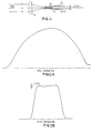
- the intensity across a beam from a laser source that is to be made more uniform has a profile 10.
- the profile 10 of the intensity is substantially the same on either side of the axis 12.
- the beam is made uniform by folding it onto itself one or more times about an axis such as the axis 12. The folding process averages out the short-range noise-like fluctuations as well as the systematic long-range variations in the original profile of the intensity.
- the beam 14 to be made more uniform is converted, using a primary optical system consisting of a cylindrical lens 16, into a wedged shaped beam which is focussed into a primary focus line at P.
- the line P is located near the end of a primary plane reflecting surface consisting of a plane mirror 18 placed near the axis of the beam and with its reflecting surface extending parallel to the axis of the beam.
- the line P extends out of the plane of the paper parallel to the reflecting surface of the mirror 18.
- the wedge angle of the light beam incident at P is 28 in the plane of the paper. From the position of the mirror it can be seen that the lower half of the incident wedged shaped beam, as denoted by rays 1, 2 and 3, leaves the mirror without reflection.
- the upper half of the incident wedged shaped beam undergoes one reflection at the mirror surface and folds over to overlap with the unreflected half of the beam to form a beam 20.
- the profile 22 of the intensity across the beam 20 after reflection by the mirror 18 is shown in Figure 1 B.
- the divergence of the beam 20 in the plane of the paper is 8, that is one-half of the incident wedge angle. While this folding operation reduces the fluctuation noise, it does not flatten the profile.
- a third reflection will provide the beam with a profile as shown in Figure 1E which has a high degree of uniformity.
- This third reflection can be obtained in several ways. One way is to refocus by means of a cylindrical lens 23 the light beam emerging from mirrors 18 and 24 into a line near 'the end of a further plane mirror 25 the reflecting surface of which lies parallel to the axis of the beam on emergence from the lens 23.
- the third reflection may alternatively be obtained more simply by making the angle between the first two mirrors 18 and 24 8/4, instead of 8/2 as shown in Figure 2B.
- the angle between the mirrors 18, 24 must be 8/2", where 8 is the incident wedge angle.
- 8 is the incident wedge angle.
- the combination of the two mirrors 18, 24 as shown in Figure 2C it is not necessary for either of the reflecting surfaces of the mirrors to extend accurately parallel to the axis of the incident wedge shaped beam. This allows the possibility of folding the beam about some line other than the axis of the beam which defines the centre of the input intensity distribution.
- the overlap will be slightly less than 100%. As a result, a little cropping will be required to pick out the most uniform portion of the beam thereby making the throughput slightly less than 100%.
- the first wedge tunnel consists of mirrors 26 and 28 which fold a beam emerging from a cylindrical lens 32 as described with reference to mirrors 18, 24 in Figure 2C and then direct the beam to a cylindrical lens 30 that has its axis at 90° to the axis of the first lens 32.
- the second wedge tunnel consists of mirrors 34 and 36 which are oriented at 90° to mirrors 26 and 28 and fold the beam in directions orthogonal to the directions of folding performed by mirrors 26, 28.
- the output light beam will be diverging after the final reflection. It is desirable to use an additional lens, focused on the primary focus line P, in order to render the output light beam collimated and, thus, more generally useful.
Landscapes
- Physics & Mathematics (AREA)
- General Physics & Mathematics (AREA)
- Optics & Photonics (AREA)
- Optical Elements Other Than Lenses (AREA)
- Optical Communication System (AREA)
- Exposure And Positioning Against Photoresist Photosensitive Materials (AREA)
Claims (7)
Applications Claiming Priority (2)
| Application Number | Priority Date | Filing Date | Title |
|---|---|---|---|
| US481011 | 1983-03-31 | ||
| US06/481,011 US4547044A (en) | 1983-03-31 | 1983-03-31 | Beam-folding wedge tunnel |
Publications (3)
| Publication Number | Publication Date |
|---|---|
| EP0121069A2 EP0121069A2 (de) | 1984-10-10 |
| EP0121069A3 EP0121069A3 (en) | 1986-04-30 |
| EP0121069B1 true EP0121069B1 (de) | 1989-01-11 |
Family
ID=23910227
Family Applications (1)
| Application Number | Title | Priority Date | Filing Date |
|---|---|---|---|
| EP84101727A Expired EP0121069B1 (de) | 1983-03-31 | 1984-02-20 | Reflexionssystem zur Verbesserung der Uniformität eines Lichtbündels |
Country Status (4)
| Country | Link |
|---|---|
| US (1) | US4547044A (de) |
| EP (1) | EP0121069B1 (de) |
| JP (1) | JPS59184317A (de) |
| DE (1) | DE3476127D1 (de) |
Families Citing this family (10)
| Publication number | Priority date | Publication date | Assignee | Title |
|---|---|---|---|---|
| US4744615A (en) * | 1986-01-29 | 1988-05-17 | International Business Machines Corporation | Laser beam homogenizer |
| DE3787463T2 (de) * | 1986-07-08 | 1994-04-28 | Komatsu Seisakusho Tokio Kk | Vorrichtung zum formen eines laserstrahls. |
| US5148442A (en) * | 1986-09-30 | 1992-09-15 | The United States Of America As Represented By The Department Of Energy | Dye lasing arrangement including an optical assembly for altering the cross-section of its pumping beam and method |
| JPH02175090A (ja) * | 1988-12-27 | 1990-07-06 | Isamu Miyamoto | レーザビーム成形装置 |
| US5303084A (en) * | 1991-08-27 | 1994-04-12 | Kaman Aerospace Corporation | Laser light beam homogenizer and imaging lidar system incorporating same |
| US6022117A (en) * | 1996-10-09 | 2000-02-08 | Canon Kabushiki Kaisha | Illuminating device for projecting light |
| JP3372785B2 (ja) * | 1996-10-09 | 2003-02-04 | キヤノン株式会社 | 照明装置及びそれを用いた撮影装置 |
| EP0881514A1 (de) * | 1997-05-30 | 1998-12-02 | Lasag Ag | Optisches Koppelelement zur räumlichen Begrenzung und Homogenisierung eines Strahls mit grossem Öffnungswinkel |
| EP1816949A1 (de) * | 2004-11-29 | 2007-08-15 | The General Hospital Corporation | Anordnungen, vorrichtungen, endoskope, katheter und verfahren für die optische bilddarstellung durch gleichzeitige beleuchtung und nachweis von mehreren punkten auf einer probe |
| US20070127005A1 (en) * | 2005-12-02 | 2007-06-07 | Asml Holding N.V. | Illumination system |
Family Cites Families (7)
| Publication number | Priority date | Publication date | Assignee | Title |
|---|---|---|---|---|
| US2604005A (en) * | 1949-01-21 | 1952-07-22 | Charles A Hahn | Projection light source and light beam modifier combination |
| US3660778A (en) * | 1970-06-16 | 1972-05-02 | Leo J Le Blanc Sr | Laser beam folding device |
| US4042821A (en) * | 1975-10-28 | 1977-08-16 | The Magnavox Company | Remote control light receiver |
| JPS5945123B2 (ja) * | 1977-07-08 | 1984-11-05 | 富士写真光機株式会社 | 線状照明法 |
| DE2916741A1 (de) * | 1979-04-25 | 1980-11-06 | Doering Geb Thurnhofer Karolin | Spiegelanordnung zum ausrichten und konzentrieren ungerichteter elektromagnetischer strahlung, insbesondere diffusen lichts und verfahren zu ihrer herstellung |
| JPS5817715B2 (ja) * | 1980-08-28 | 1983-04-08 | 積水樹脂株式会社 | フエンスの製造方法 |
| US4382656A (en) * | 1980-11-12 | 1983-05-10 | The Foxboro Company | Non-imaging optical energy transfer system |
-
1983
- 1983-03-31 US US06/481,011 patent/US4547044A/en not_active Expired - Fee Related
- 1983-11-30 JP JP58224566A patent/JPS59184317A/ja active Pending
-
1984
- 1984-02-20 EP EP84101727A patent/EP0121069B1/de not_active Expired
- 1984-02-20 DE DE8484101727T patent/DE3476127D1/de not_active Expired
Also Published As
| Publication number | Publication date |
|---|---|
| DE3476127D1 (en) | 1989-02-16 |
| EP0121069A2 (de) | 1984-10-10 |
| JPS59184317A (ja) | 1984-10-19 |
| EP0121069A3 (en) | 1986-04-30 |
| US4547044A (en) | 1985-10-15 |
Similar Documents
| Publication | Publication Date | Title |
|---|---|---|
| US4826299A (en) | Linear deiverging lens | |
| US5055653A (en) | Laser beam machining device | |
| KR960013550A (ko) | 레이저가공용 광학장치 | |
| ATE14263T1 (de) | Wellenlaengensortierer. | |
| GB2261528A (en) | High power light source | |
| JPS62258416A (ja) | 光線集中方法および装置 | |
| US5285320A (en) | Mirror for changing the geometrical form of a light beam | |
| JPH01306088A (ja) | 可変ビームレーザ加工装置 | |
| EP0102221B1 (de) | Gerät zum Projizieren von Leuchtspuren auf ein Objekt mittels eines Laserstrahls | |
| CA2171590A1 (en) | Method and device for focusing laser beam | |
| EP0121069A2 (de) | Reflexionssystem zur Verbesserung der Uniformität eines Lichtbündels | |
| JPH07175013A (ja) | 光ビーム・エキスパンダー | |
| KR100659438B1 (ko) | 레이저 가공 장치 및 레이저 가공 방법 | |
| US4796965A (en) | Optical scanning device | |
| EP0196335A4 (de) | Projektor. | |
| DE69737669T2 (de) | Verfahren und Vorrichtung zum Steuern des Durchmessers eines Lichtstrahls | |
| US4192578A (en) | Method of projecting a line image of uniform brightness | |
| KR970703540A (ko) | 광학 광선 분할 소자(Optical beam-splitting element) | |
| Latta et al. | Beam intensity uniformization by mirror folding | |
| US4398787A (en) | Optical leverage telecentric scanning apparatus | |
| CA1284046C (en) | Wobble correction by two reflections on a facet without bow | |
| US4707055A (en) | Scanning apparatus | |
| GB1281773A (en) | Optical deflection apparatus | |
| US5153768A (en) | Multiple wavelength, multiple diode laser ROS | |
| JPS63189981A (ja) | 走査パタ−ン読取装置 |
Legal Events
| Date | Code | Title | Description |
|---|---|---|---|
| PUAI | Public reference made under article 153(3) epc to a published international application that has entered the european phase |
Free format text: ORIGINAL CODE: 0009012 |
|
| AK | Designated contracting states |
Designated state(s): DE FR GB |
|
| 17P | Request for examination filed |
Effective date: 19841123 |
|
| PUAL | Search report despatched |
Free format text: ORIGINAL CODE: 0009013 |
|
| RHK1 | Main classification (correction) |
Ipc: G02B 17/00 |
|
| AK | Designated contracting states |
Kind code of ref document: A3 Designated state(s): DE FR GB |
|
| 17Q | First examination report despatched |
Effective date: 19870601 |
|
| GRAA | (expected) grant |
Free format text: ORIGINAL CODE: 0009210 |
|
| AK | Designated contracting states |
Kind code of ref document: B1 Designated state(s): DE FR GB |
|
| REF | Corresponds to: |
Ref document number: 3476127 Country of ref document: DE Date of ref document: 19890216 |
|
| ET | Fr: translation filed | ||
| PLBE | No opposition filed within time limit |
Free format text: ORIGINAL CODE: 0009261 |
|
| STAA | Information on the status of an ep patent application or granted ep patent |
Free format text: STATUS: NO OPPOSITION FILED WITHIN TIME LIMIT |
|
| 26N | No opposition filed | ||
| PGFP | Annual fee paid to national office [announced via postgrant information from national office to epo] |
Ref country code: DE Payment date: 19910204 Year of fee payment: 8 |
|
| PGFP | Annual fee paid to national office [announced via postgrant information from national office to epo] |
Ref country code: GB Payment date: 19920113 Year of fee payment: 9 |
|
| PGFP | Annual fee paid to national office [announced via postgrant information from national office to epo] |
Ref country code: FR Payment date: 19920124 Year of fee payment: 9 |
|
| PG25 | Lapsed in a contracting state [announced via postgrant information from national office to epo] |
Ref country code: DE Effective date: 19921103 |
|
| PG25 | Lapsed in a contracting state [announced via postgrant information from national office to epo] |
Ref country code: GB Effective date: 19930220 |
|
| GBPC | Gb: european patent ceased through non-payment of renewal fee |
Effective date: 19930220 |
|
| PG25 | Lapsed in a contracting state [announced via postgrant information from national office to epo] |
Ref country code: FR Effective date: 19931029 |
|
| REG | Reference to a national code |
Ref country code: FR Ref legal event code: ST |