EP0121097A2 - Gerät zur Identifizierung von Sektoren auf einem Datenspeichergerät mit einem Vielspurmagnetkopf - Google Patents
Gerät zur Identifizierung von Sektoren auf einem Datenspeichergerät mit einem Vielspurmagnetkopf Download PDFInfo
- Publication number
- EP0121097A2 EP0121097A2 EP84102105A EP84102105A EP0121097A2 EP 0121097 A2 EP0121097 A2 EP 0121097A2 EP 84102105 A EP84102105 A EP 84102105A EP 84102105 A EP84102105 A EP 84102105A EP 0121097 A2 EP0121097 A2 EP 0121097A2
- Authority
- EP
- European Patent Office
- Prior art keywords
- sector
- data
- sectors
- read
- tracks
- Prior art date
- Legal status (The legal status is an assumption and is not a legal conclusion. Google has not performed a legal analysis and makes no representation as to the accuracy of the status listed.)
- Ceased
Links
Images

Classifications
-
- G—PHYSICS
- G11—INFORMATION STORAGE
- G11B—INFORMATION STORAGE BASED ON RELATIVE MOVEMENT BETWEEN RECORD CARRIER AND TRANSDUCER
- G11B20/00—Signal processing not specific to the method of recording or reproducing; Circuits therefor
- G11B20/10—Digital recording or reproducing
- G11B20/12—Formatting, e.g. arrangement of data block or words on the record carriers
-
- G—PHYSICS
- G11—INFORMATION STORAGE
- G11B—INFORMATION STORAGE BASED ON RELATIVE MOVEMENT BETWEEN RECORD CARRIER AND TRANSDUCER
- G11B27/00—Editing; Indexing; Addressing; Timing or synchronising; Monitoring; Measuring tape travel
- G11B27/10—Indexing; Addressing; Timing or synchronising; Measuring tape travel
- G11B27/19—Indexing; Addressing; Timing or synchronising; Measuring tape travel by using information detectable on the record carrier
- G11B27/28—Indexing; Addressing; Timing or synchronising; Measuring tape travel by using information detectable on the record carrier by using information signals recorded by the same method as the main recording
- G11B27/30—Indexing; Addressing; Timing or synchronising; Measuring tape travel by using information detectable on the record carrier by using information signals recorded by the same method as the main recording on the same track as the main recording
- G11B27/3027—Indexing; Addressing; Timing or synchronising; Measuring tape travel by using information detectable on the record carrier by using information signals recorded by the same method as the main recording on the same track as the main recording used signal is digitally coded
-
- G—PHYSICS
- G11—INFORMATION STORAGE
- G11B—INFORMATION STORAGE BASED ON RELATIVE MOVEMENT BETWEEN RECORD CARRIER AND TRANSDUCER
- G11B5/00—Recording by magnetisation or demagnetisation of a record carrier; Reproducing by magnetic means; Record carriers therefor
- G11B5/012—Recording on, or reproducing or erasing from, magnetic disks
-
- G—PHYSICS
- G11—INFORMATION STORAGE
- G11B—INFORMATION STORAGE BASED ON RELATIVE MOVEMENT BETWEEN RECORD CARRIER AND TRANSDUCER
- G11B2220/00—Record carriers by type
- G11B2220/20—Disc-shaped record carriers
-
- G—PHYSICS
- G11—INFORMATION STORAGE
- G11B—INFORMATION STORAGE BASED ON RELATIVE MOVEMENT BETWEEN RECORD CARRIER AND TRANSDUCER
- G11B2220/00—Record carriers by type
- G11B2220/20—Disc-shaped record carriers
- G11B2220/25—Disc-shaped record carriers characterised in that the disc is based on a specific recording technology
- G11B2220/2508—Magnetic discs
Definitions
- This invention pertains to direct access disk storage devices and more particularly to a format and mode of operation that enables all sector identifier (ID) fields in a cylinder to be read in a single revolution.
- ID sector identifier
- a disk file is most commonly operated in a physical mode wherein a track is read continuously sector by sector in sequence.
- a second mode of operation is a logical mode wherein the sectors within a cylinder are staggered in a mount 1/n of a sector wherein n is a number of tracks forming the cylinder.
- ID scan mode of operation permits the ID or identifier sector portions of a sector for each track to be read during the passage of a single sector arcuate length past the head assembly. By continuing and repeating this process during the passage of each arc equivalent to a sector, all the sector ID's are read during a single revolution of the disk assembly.
- This mode of operation not only permits all ID fields to be read in a single revolution, but also affords enough time between successive comparisons of an address to an ID field to permit a mode change to physical mode when a desired sector ID is identified. This permits the data to be read immediately and results in an average delay or latency of one-half revolution when seeking a sector within a cylinder and a maximum delay of one full revolution.
- This sector staggering format also permits the data rate of the file to be tailored to any slower data rate by selecting as the logical sequence the head and sector with the proper intersector delay to the nearest 1/n sector time.
- the invention is shown in the environment of a disk drive that has a dedicated servo surface and 14 heads mounted on a single actuator, which is combination with a multi disk media assembly that rotates in unison defines a single cylinder of 14 tracks.
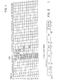
- a typical sector format is shown in figure 2 which includes an initial gap of 20 bytes duration, a 6 byte identifier (ID) field, a 2 byte check field and a gap of 22 bytes.
- the data portion of the data sector has two 256 byte data fields separated by an 8 byte error correction field and a 20 byte gap and followed by an 8 byte error correction field and an 11 byte gap to complete the sector.
- the sectors are uniformly staggered by one-fourteenth sector between successively staggered sectors.
- this causes successively staggered sectors to be displaced by 43 and one-half bytes.
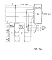
- Figures 3A and 3B illustrate the control circuit that controls the head select in the physical mode wherein a single track is read continuously or the scan mode in which all ID fields are read during a single revolution of the media assembly.
- the control counter 6 is set to 0 ⁇ by the index mark signal which indicates the beginning of sector 0, track 0.
- the index mark signal on line 7 also sets the next head register to head 0.
- the counter 6 functions to count to 43 1/2 bytes and reset to 0.
- Counter 6 receives a pulse train from the servo clock which generates 1 pulse for each 1 1/2 bytes of the data sectors. Accordingly, counter 6 decodes a count of 29 to provide a 1 count pulse on sector strobe line 9 and also reset the counter to 0 ⁇ . Also decoded by the counter is a count of 24 on line 11 which advances the count in the next head register 16.
- Multiplexer 18 functions in accordance with the condition of ID scan line 20 to load the present head register with the content of either the next head register 16 (when the ID scan mode line 20 is active) or the head load register 24 (when the ID scan mode line 20 is inactive).
- the selected content of multiplexer 18 is gated to present head register 22 by the sector strobe pulse on line 9. If the present head register 22 is loaded with the content of the next head register 16, both register 16 and 22 contain the same head address and a compare occurs at comparator 26 causing a sector pulse output on line 27 during the sector strobe pulse.
- the content of the present head register 22 is also available on the head select bus 28.
- the value in the next head register 16 is loaded to the present head register 22 each time a sector strobe signal on line 9 occurs. This enables an ID field on each track to be read during each sector time and all ID fields to be read during a single revolution of the media.
- the ID scan mode line 20 is inactive causing the content of the head load register 24 to be gated into the present head register 22. The same track location will then continuously appear on the head select bus 28 to make such head continuously active, as long as a new address on bus 30 is not gated by a signal on the load head address line and the ID scan mode select line remains inactive. It will also be noted that under such conditions the sector pulse from comparator 26 will occur only at the beginning of the sectors corresponding to the track associated with the head indicated on the head select bus 28.
- the sector format which enable the ID scan mode to read all ID field during a single revolution may also be utilized in a logical mode to permit a data rate that is reduced by one-fourteenth increments in the illustrated embodiment of a 14 head device.
- the fastest reading data rate is continuous sectors on a single track such as numbered sectors 0, 1, 2, 3.
- the fastest rate is obtained through switching heads in a sequence such as sectors , 51, 102, 153 to enable minimizing the intersector gaps.
- Progressively reduced data rates can be obtained by sector sequences such as 0 ⁇ , 101, 202, 303 and 0, 151, 302, 453.
Landscapes
- Engineering & Computer Science (AREA)
- Signal Processing (AREA)
- Signal Processing For Digital Recording And Reproducing (AREA)
- Indexing, Searching, Synchronizing, And The Amount Of Synchronization Travel Of Record Carriers (AREA)
Applications Claiming Priority (2)
| Application Number | Priority Date | Filing Date | Title |
|---|---|---|---|
| US06/482,099 US4504873A (en) | 1983-04-04 | 1983-04-04 | Identification field scan apparatus |
| US482099 | 1990-02-20 |
Publications (2)
| Publication Number | Publication Date |
|---|---|
| EP0121097A2 true EP0121097A2 (de) | 1984-10-10 |
| EP0121097A3 EP0121097A3 (de) | 1987-08-05 |
Family
ID=23914651
Family Applications (1)
| Application Number | Title | Priority Date | Filing Date |
|---|---|---|---|
| EP84102105A Ceased EP0121097A3 (de) | 1983-04-04 | 1984-02-29 | Gerät zur Identifizierung von Sektoren auf einem Datenspeichergerät mit einem Vielspurmagnetkopf |
Country Status (3)
| Country | Link |
|---|---|
| US (1) | US4504873A (de) |
| EP (1) | EP0121097A3 (de) |
| JP (1) | JPS6022776A (de) |
Families Citing this family (12)
| Publication number | Priority date | Publication date | Assignee | Title |
|---|---|---|---|---|
| EP0177737A3 (en) * | 1984-08-28 | 1988-07-06 | Fuji Photo Film Co., Ltd. | Optical memory disk and track access therefor |
| JPS6278623A (ja) * | 1985-10-02 | 1987-04-10 | Toshiba Corp | 磁気デイスク装置 |
| JP2500239Y2 (ja) * | 1990-10-02 | 1996-06-05 | 矢崎総業株式会社 | コネクタの固定構造 |
| JP2560143B2 (ja) * | 1990-10-19 | 1996-12-04 | 富士通株式会社 | 直接アクセス装置の制御方式 |
| US5370553A (en) * | 1993-03-12 | 1994-12-06 | At&T Corp. | Adjustable terminations in equipment housing for cables |
| WO1995024038A1 (en) * | 1994-03-03 | 1995-09-08 | Cirrus Logic, Inc. | Defect management for automatic track processing without id field |
| US6025966A (en) * | 1994-03-03 | 2000-02-15 | Cirrus Logic, Inc. | Defect management for automatic track processing without ID field |
| US5696775A (en) * | 1994-09-23 | 1997-12-09 | Cirrus Logic, Inc. | Method and apparatus for detecting the transfer of a wrong sector |
| US5667398A (en) * | 1995-09-13 | 1997-09-16 | General Motors Corporation | Modular connection system |
| US5760993A (en) * | 1995-12-14 | 1998-06-02 | International Business Machines Corporation | Information storage device with an odd number of track sequences in a zone |
| US7522760B1 (en) | 2003-10-17 | 2009-04-21 | Carreker Corporation | Method for inspecting document images |
| US7461197B2 (en) * | 2005-12-19 | 2008-12-02 | Broadcom Corporation | Disk formatter and methods for use therewith |
Family Cites Families (6)
| Publication number | Priority date | Publication date | Assignee | Title |
|---|---|---|---|---|
| BE626488A (de) * | 1961-12-26 | |||
| JPS5172413A (ja) * | 1974-12-20 | 1976-06-23 | Hitachi Ltd | Indetsukusushingohatsuseihoshiki |
| US4016603A (en) * | 1975-05-30 | 1977-04-05 | International Business Machines Corporation | Disk storage apparatus having signals recorded in a specific format |
| US4210941A (en) * | 1975-08-11 | 1980-07-01 | Casio Computer Co., Ltd. | Data-recording device |
| JPS5284708A (en) * | 1975-12-31 | 1977-07-14 | Fujitsu Ltd | Magnetic disc apparatus |
| NL7702570A (nl) * | 1977-03-10 | 1978-09-12 | Philips Nv | Magneetschijfgeheugen en magneetschijf voor dat geheugen. |
-
1983
- 1983-04-04 US US06/482,099 patent/US4504873A/en not_active Expired - Lifetime
-
1984
- 1984-01-18 JP JP59005870A patent/JPS6022776A/ja active Pending
- 1984-02-29 EP EP84102105A patent/EP0121097A3/de not_active Ceased
Also Published As
| Publication number | Publication date |
|---|---|
| US4504873A (en) | 1985-03-12 |
| EP0121097A3 (de) | 1987-08-05 |
| JPS6022776A (ja) | 1985-02-05 |
Similar Documents
| Publication | Publication Date | Title |
|---|---|---|
| US4001883A (en) | High density data storage on magnetic disk | |
| US4656532A (en) | Sector identification method for hard sectored hard files | |
| US6105104A (en) | Method and apparatus for optimizing the data transfer rate to and from a plurality of disk surfaces | |
| EP0026320B1 (de) | Datenaufzeichnungs/-wiedergabegerät und Verfahren zu dessen Betrieb | |
| US6606589B1 (en) | Disk storage subsystem with internal parallel data path and non-volatile memory | |
| US4811124A (en) | Defect skipping mechanism for disk drives | |
| JP2576512B2 (ja) | デ−タレコ−ダ | |
| US5757568A (en) | System and method for encoding a servo address | |
| US4504873A (en) | Identification field scan apparatus | |
| JPH0620393A (ja) | ディスク駆動システム | |
| US5274507A (en) | Parallel data encoding for moving media | |
| KR19980020110A (ko) | 하드 디스크 드라이브의 데이타 어드레스 마크구성 및 처리방법 | |
| WO2004010433A1 (ja) | データ記録再生装置及びデータ記録再生方法 | |
| US5864440A (en) | Data processing method and data storage system | |
| US4926272A (en) | Method for controlling a rotating storage unit | |
| US6104558A (en) | System and method of encoding an index mark into a servo address | |
| US4663733A (en) | Programmable universal synchronization byte detector | |
| JP2002184113A (ja) | ディスク装置 | |
| US6259577B1 (en) | Method and apparatus for organizing servo data to expand data region and counting sector numbers from headerless servo format in a disk drive | |
| US6005728A (en) | Disk recording medium for embodying high capacity hard disk drive | |
| EP0459726A2 (de) | Magnetplattengerät | |
| US6366419B1 (en) | Method of head disc assembly serial number encoding and retrieval and disc drive apparatus having an encoded head disc assembly serial number | |
| US4575774A (en) | Disk subsystem read write control | |
| KR950002701B1 (ko) | 고속 억세스용 하드 디스크의 억세스 회로 | |
| KR100273750B1 (ko) | 하드디스크드라이브의헤드위치검출방법 |
Legal Events
| Date | Code | Title | Description |
|---|---|---|---|
| PUAI | Public reference made under article 153(3) epc to a published international application that has entered the european phase |
Free format text: ORIGINAL CODE: 0009012 |
|
| AK | Designated contracting states |
Designated state(s): DE FR GB |
|
| 17P | Request for examination filed |
Effective date: 19841123 |
|
| PUAL | Search report despatched |
Free format text: ORIGINAL CODE: 0009013 |
|
| AK | Designated contracting states |
Kind code of ref document: A3 Designated state(s): DE FR GB |
|
| 17Q | First examination report despatched |
Effective date: 19871030 |
|
| STAA | Information on the status of an ep patent application or granted ep patent |
Free format text: STATUS: THE APPLICATION IS DEEMED TO BE WITHDRAWN |
|
| 18D | Application deemed to be withdrawn |
Effective date: 19891213 |
|
| 18RA | Request filed for re-establishment of rights before grant |
Effective date: 19900724 |
|
| 18RR | Decision to grant the request for re-establishment of rights before grant |
Free format text: 900817 ANGENOMMEN |
|
| R18Z | Request filed for re-establishment of rights before grant (corrected) |
Free format text: 900718 |
|
| 18R | Application refused |
Effective date: 19910510 |
|
| RIN1 | Information on inventor provided before grant (corrected) |
Inventor name: HOLTAN, DONALD CARLTON Inventor name: BANDY, PETER BURGHARDT Inventor name: DANEN, JOHN ANTHONY Inventor name: HEISE, NYLES, NORBER |