EP0121173B1 - Méthode de fabrication d'un paquet de tôles feuilletées pour machines et appareils électriques - Google Patents
Méthode de fabrication d'un paquet de tôles feuilletées pour machines et appareils électriques Download PDFInfo
- Publication number
- EP0121173B1 EP0121173B1 EP84103014A EP84103014A EP0121173B1 EP 0121173 B1 EP0121173 B1 EP 0121173B1 EP 84103014 A EP84103014 A EP 84103014A EP 84103014 A EP84103014 A EP 84103014A EP 0121173 B1 EP0121173 B1 EP 0121173B1
- Authority
- EP
- European Patent Office
- Prior art keywords
- stack
- laminated plates
- laminated
- sheet metal
- plates
- Prior art date
- Legal status (The legal status is an assumption and is not a legal conclusion. Google has not performed a legal analysis and makes no representation as to the accuracy of the status listed.)
- Expired
Links
- 238000004519 manufacturing process Methods 0.000 title description 6
- 238000000034 method Methods 0.000 claims description 13
- 238000000137 annealing Methods 0.000 claims description 6
- 239000011347 resin Substances 0.000 claims description 6
- 229920005989 resin Polymers 0.000 claims description 6
- 230000006835 compression Effects 0.000 claims description 5
- 238000007906 compression Methods 0.000 claims description 5
- 238000005266 casting Methods 0.000 claims description 2
- 229920006395 saturated elastomer Polymers 0.000 claims 1
- 239000002184 metal Substances 0.000 description 46
- 241000446313 Lamella Species 0.000 description 16
- 238000003475 lamination Methods 0.000 description 14
- 238000003825 pressing Methods 0.000 description 10
- 210000002105 tongue Anatomy 0.000 description 6
- 238000004080 punching Methods 0.000 description 4
- 210000000078 claw Anatomy 0.000 description 2
- 239000011248 coating agent Substances 0.000 description 2
- 238000000576 coating method Methods 0.000 description 2
- 238000005470 impregnation Methods 0.000 description 2
- 239000000463 material Substances 0.000 description 2
- 230000001590 oxidative effect Effects 0.000 description 2
- 238000004806 packaging method and process Methods 0.000 description 2
- 125000006850 spacer group Chemical group 0.000 description 2
- 229910000831 Steel Inorganic materials 0.000 description 1
- 230000001419 dependent effect Effects 0.000 description 1
- 238000005516 engineering process Methods 0.000 description 1
- 230000002349 favourable effect Effects 0.000 description 1
- 238000005304 joining Methods 0.000 description 1
- 238000012544 monitoring process Methods 0.000 description 1
- 239000007787 solid Substances 0.000 description 1
- 239000010959 steel Substances 0.000 description 1
- 238000003466 welding Methods 0.000 description 1
- 238000004804 winding Methods 0.000 description 1
Images
Classifications
-
- H—ELECTRICITY
- H02—GENERATION; CONVERSION OR DISTRIBUTION OF ELECTRIC POWER
- H02K—DYNAMO-ELECTRIC MACHINES
- H02K15/00—Processes or apparatus specially adapted for manufacturing, assembling, maintaining or repairing of dynamo-electric machines
- H02K15/02—Processes or apparatus specially adapted for manufacturing, assembling, maintaining or repairing of dynamo-electric machines of stator or rotor bodies
- H02K15/021—Magnetic cores
-
- H—ELECTRICITY
- H02—GENERATION; CONVERSION OR DISTRIBUTION OF ELECTRIC POWER
- H02K—DYNAMO-ELECTRIC MACHINES
- H02K1/00—Details of the magnetic circuit
- H02K1/04—Details of the magnetic circuit characterised by the material used for insulating the magnetic circuit or parts thereof
-
- H—ELECTRICITY
- H02—GENERATION; CONVERSION OR DISTRIBUTION OF ELECTRIC POWER
- H02K—DYNAMO-ELECTRIC MACHINES
- H02K2201/00—Specific aspects not provided for in the other groups of this subclass relating to the magnetic circuits
- H02K2201/09—Magnetic cores comprising laminations characterised by being fastened by caulking
-
- Y—GENERAL TAGGING OF NEW TECHNOLOGICAL DEVELOPMENTS; GENERAL TAGGING OF CROSS-SECTIONAL TECHNOLOGIES SPANNING OVER SEVERAL SECTIONS OF THE IPC; TECHNICAL SUBJECTS COVERED BY FORMER USPC CROSS-REFERENCE ART COLLECTIONS [XRACs] AND DIGESTS
- Y10—TECHNICAL SUBJECTS COVERED BY FORMER USPC
- Y10T—TECHNICAL SUBJECTS COVERED BY FORMER US CLASSIFICATION
- Y10T29/00—Metal working
- Y10T29/49—Method of mechanical manufacture
- Y10T29/49002—Electrical device making
- Y10T29/49009—Dynamoelectric machine
-
- Y—GENERAL TAGGING OF NEW TECHNOLOGICAL DEVELOPMENTS; GENERAL TAGGING OF CROSS-SECTIONAL TECHNOLOGIES SPANNING OVER SEVERAL SECTIONS OF THE IPC; TECHNICAL SUBJECTS COVERED BY FORMER USPC CROSS-REFERENCE ART COLLECTIONS [XRACs] AND DIGESTS
- Y10—TECHNICAL SUBJECTS COVERED BY FORMER USPC
- Y10T—TECHNICAL SUBJECTS COVERED BY FORMER US CLASSIFICATION
- Y10T29/00—Metal working
- Y10T29/49—Method of mechanical manufacture
- Y10T29/49002—Electrical device making
- Y10T29/4902—Electromagnet, transformer or inductor
- Y10T29/49075—Electromagnet, transformer or inductor including permanent magnet or core
- Y10T29/49078—Laminated
Definitions
- the invention relates to a method for producing a package from layered sheet metal laminations for electrical machines and devices according to the preamble of claim 1; such a method is known from DE-AS 14 33 774.
- the known method for producing rotor and / or stator plates of electrical machines by means of annealing treatment after punching the plates in a reducing atmosphere is characterized in that the stands punched out of a steel plate with higher electrical losses than with conventional dynamo plates with a hardness which is favorable in terms of stamping technology - or rotor plates spaced from each other, hung on mandrels, placed in a continuous furnace in a reducing atmosphere of about 800 ° C, then cooled to about 550 to 6500C and then provided with an insulating coating from this temperature in an oxidizing gas atmosphere; the sheets which have been electrically refined in this way are then produced in accordance with a predetermined sheet package parameter, such as, for. B. layered the number of laminations per laminated core, weight or height of the laminated core, compressed with plane-parallel end faces and z. B. secured in place by riveting, screwing or welding the laminated core.
- a predetermined sheet package parameter such as, for. B. layered
- the object of the present invention is to simplify the production of packages from layered sheet metal lamellae, which after punching have to be subjected to an annealing treatment with a gas atmosphere covering the surface of the sheet metal lamellae, in particular in such a way that, in view of the automation of the manufacturing process, the number of individual processing or assembly steps can be reduced.
- the method according to the invention allows the use of the known stamping-packetizing method with its simple possibility of forming a laminated core and holding the laminations among one another immediately after the stamping of the laminations, without this resulting in the use of cheap sheets and the treatment of the punched-out laminations required a reducing atmosphere, which requires free access to the entire surface of the metal fins, must be dispensed with;
- the pre-pressing on the one hand already achieves a sufficiently secure bond between the laminations of a laminated core and, on the other hand, a sufficient distance between the individual laminations can be ensured, which ensures safe access to a reducing atmosphere for the electrical finishing of the sheets and, if necessary, an additional oxidizing gas Atmosphere for an insulating coating.
- the subsequent re-pressing then axially compresses the laminated core into its final design by pressing rams pressing against both end faces and running parallel to one another.
- the spacing stops expediently consist of flaps which are connected on the outer circumference of a sheet metal lamella radially on the inside with the sheet metal lamella and are otherwise stamped out and bent out on the edge.
- the laminations of a laminated core are layered without an envelope; which after the plane-parallel compression of the laminated core on one side Side of this package, possibly due to different material thickness of the gaps provided for the stamped sheet metal strip, are filled with casting resin.
- Such a filling can take place in the usual cast resin impregnation of the finished laminated core.
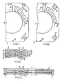
- sheet metal tongues 11, 12 or 21, 22 are stamped or stamped in to form elevations or depressions for joining the sheet metal lamellae together.
- the sheet metal tongues 11, 12 and 21, 22 are punched free on their long sides, while they remain integrally connected to them on their short end faces in the plane of the sheet metal laminations 1 and 2, respectively.
- the sheet-metal tongues 11, 12 and 21, 22 are pressed out conically axially out of the plane of the sheet-metal fins 1 and 2 in their punched-out area between the end faces.
- the pressed-out sheet metal tongue 12 of the one sheet metal lamella 1 engages in the slit-shaped opening created by pressing out the sheet metal tongue 22 of the following sheet metal lamella 2 and claws in a positive and / or non-positive manner with the side walls of this opening.
- the same type of connection is repeated - as can be seen in FIG. 3 by clawing the tip of the sheet metal tongue 22 of the sheet metal lamella 2 by engaging in the opening of the sheet metal lamella underneath, which is identical to the sheet metal lamella 1.
- FIG. 3 shows a section of a laminated core, the laminations 1, 2, 1 of which are joined together by pressing to a mutual minimum distance a and which, in this state, can be brought as a bandage into an annealing furnace for treatment in a reducing gas atmosphere.
- spacers 13-17 and 23-27 are arranged as spacing stops on the outer circumference of each sheet metal lamella 1 or 2 which are connected radially on the inside with the sheet metal lamella and are otherwise punched out and axially bent out.
- the tabs 13-17 of the sheet metal lamella 1 are offset in relation to the tabs 23-27 of the sheet lamella 2 next in the sheet metal package in such a way that, as can be seen from FIG. 3, the parts of the spacer stops which are axially bent out from the plane of the sheet metal lamellae are only open a flat, not bent-out part of the next sheet metal lamella can come to rest.
- FIG. 4 shows the pre-pressed bandage of the laminated core according to FIG. 3 after the final pressing.
- the pressure of a pressure device which presses plane-parallel to one another on both end faces of the laminated core is increased to such an extent that the bent-out tabs 13-17 and 23-27 bend back into the plane of their laminated plates 1 to 2.
- the laminations of a laminated core are layered without an envelope, it can happen that - as shown in Fig. 4 in the right part of the sectional view - between the laminations Spaces are created while the sheet metal fins are close together on the left outside of the sheet stack.
- the laminated core which has been annealed and stamped in such a simple manner, is subjected to an impregnation with hardening cast resin, so that the interstices are filled with cast resin and a solid cast resin intermediate layer 4 is formed between the laminations.
- the fixed assembly is additionally secured even under the pressure of the bearing plates axially counter-tensioned during the final assembly of the motor.
Landscapes
- Engineering & Computer Science (AREA)
- Power Engineering (AREA)
- Manufacturing & Machinery (AREA)
- Manufacture Of Motors, Generators (AREA)
Claims (6)
Applications Claiming Priority (2)
| Application Number | Priority Date | Filing Date | Title |
|---|---|---|---|
| DE3311852 | 1983-03-31 | ||
| DE3311852A DE3311852C2 (de) | 1983-03-31 | 1983-03-31 | Verfahren zur Herstellung eines Paketes aus geschichteten Blechlamellen für elektrische Maschinen und Geräte |
Publications (3)
| Publication Number | Publication Date |
|---|---|
| EP0121173A2 EP0121173A2 (fr) | 1984-10-10 |
| EP0121173A3 EP0121173A3 (en) | 1985-07-10 |
| EP0121173B1 true EP0121173B1 (fr) | 1987-09-23 |
Family
ID=6195274
Family Applications (1)
| Application Number | Title | Priority Date | Filing Date |
|---|---|---|---|
| EP84103014A Expired EP0121173B1 (fr) | 1983-03-31 | 1984-03-19 | Méthode de fabrication d'un paquet de tôles feuilletées pour machines et appareils électriques |
Country Status (4)
| Country | Link |
|---|---|
| US (1) | US4538345A (fr) |
| EP (1) | EP0121173B1 (fr) |
| JP (1) | JPS59185144A (fr) |
| DE (2) | DE3311852C2 (fr) |
Cited By (1)
| Publication number | Priority date | Publication date | Assignee | Title |
|---|---|---|---|---|
| DE102016005329A1 (de) * | 2016-04-26 | 2017-10-26 | Kienle + Spiess Gmbh | Lamellenpaket zur Herstellung von Statoren und/oder Rotoren von Elektromotoren und Generatoren |
Families Citing this family (38)
| Publication number | Priority date | Publication date | Assignee | Title |
|---|---|---|---|---|
| US4728842A (en) * | 1986-09-29 | 1988-03-01 | Carbet Corporation | Laminated assembly for a dynamoelectric machine and method for manufacturing laminated assemblies having ridges formed on projections which interlock with recesses of adjacent laminations |
| US4809429A (en) * | 1986-09-29 | 1989-03-07 | Carbet Corporation | Apparatus for manufacturing laminated assemblies having ridges formed on projections which interlock with recesses of adjacent laminations |
| US5075150A (en) * | 1987-06-22 | 1991-12-24 | Linton And Hirst | Pack of laminations with projections and depressions in torsionally flexible contact |
| DE3879930D1 (de) * | 1988-04-22 | 1993-05-06 | Mannesmann Ag | Verfahren zum herstellen von ankern des elektromagnetspulen-anker-systems fuer matrixdruckkoepfe und anker, insbes. der klappankerbauart. |
| DE3818195A1 (de) * | 1988-05-28 | 1989-12-07 | Asea Brown Boveri | Spindeln mit elektromotorischem einzelantrieb fuer eine spinnereimaschine |
| US4972113A (en) * | 1989-07-14 | 1990-11-20 | Emerson Electric Co. | Structure and method of assembly of bearing support means to the stator assembly of an electric motor |
| US5142178A (en) * | 1991-04-12 | 1992-08-25 | Emerson Electric Co. | Apparatus for aligning stacked laminations of a dynamoelectric machine |
| US7249546B1 (en) | 1991-05-13 | 2007-07-31 | Franklin Electric Co., Ltd. | Die-shaping apparatus and process and product formed thereby |
| US5349741A (en) * | 1992-06-24 | 1994-09-27 | L.H. Carbide Corporation | Method of making an interlocked core spaced for anneal penetration |
| JPH0614481A (ja) * | 1992-06-25 | 1994-01-21 | Mitsubishi Electric Corp | 電機子鉄心 |
| US5809638A (en) * | 1992-10-26 | 1998-09-22 | L.H. Carbide Corporation | Method for manufacturing laminated parts with center interlock |
| US5331735A (en) * | 1993-04-28 | 1994-07-26 | General Electric Company | Method of forming a flexible connector |
| DE9416669U1 (de) * | 1994-10-17 | 1994-12-22 | AEG Zähler GmbH, 31785 Hameln | Kernpaket aus aufeinandergeschichteten Blechlamellen |
| US6195875B1 (en) | 1996-06-05 | 2001-03-06 | L.H. Carbide Corporation | Apparatus for manufacturing long, slender lamina stacks from nonuniform laminae |
| US6163949A (en) | 1996-06-05 | 2000-12-26 | L.H. Carbide Corporation | Method for manufacturing long, slender lamina stack from nonuniform laminae |
| US5799387A (en) * | 1996-06-05 | 1998-09-01 | L.H. Carbide Corpordation | Lamina stack having a plurality of outer perimeter configurations and an apparatus and method for manufacturing said stack |
| US6636137B1 (en) | 1996-06-05 | 2003-10-21 | L.H. Carbide Corporation | Ignition coil assembly |
| US5755023A (en) * | 1996-06-05 | 1998-05-26 | L.H. Carbide Corporation | Lamina stack with at least one lamina layer having a plurality of discrete segments and an apparatus and method for manufacturing said stack |
| US5771565A (en) * | 1997-01-14 | 1998-06-30 | Oberg Industries, Inc. | Method of making a dimple compensated laminar stack |
| US5826323A (en) * | 1997-01-14 | 1998-10-27 | Oberg Industries, Inc. | Method of making a height compensated laminar stack |
| US5992003A (en) * | 1997-11-13 | 1999-11-30 | Oberg Industries, Inc. | Method for spacing laminations |
| DE19842948A1 (de) * | 1998-09-18 | 2000-03-30 | Siemens Ag | Elektromotor |
| US6504274B2 (en) * | 2001-01-04 | 2003-01-07 | General Electric Company | Generator stator cooling design with concavity surfaces |
| US6877214B2 (en) * | 2002-11-05 | 2005-04-12 | L. H. Carbide Corporation | Method of manufacturing a stack of laminations |
| DE10258606A1 (de) * | 2002-12-16 | 2004-06-24 | Robert Bosch Gmbh | Elektrische Maschine |
| EP1833145B1 (fr) | 2006-03-10 | 2012-05-16 | Kienle + Spiess GmbH | Procédé, outil et dispositif destinés à la production de paquets de tôles et un paquet de tôles |
| DE102008057390A1 (de) * | 2008-11-14 | 2010-05-20 | Robert Bosch Gmbh | Segmentierte Stator-/Rotorelemente von Elektromotoren |
| JP5641902B2 (ja) | 2010-10-08 | 2014-12-17 | 日本発條株式会社 | モーターのステーター・コア及び製造方法 |
| JP5519550B2 (ja) * | 2011-02-15 | 2014-06-11 | トヨタ自動車株式会社 | 分割コアおよびステータコア |
| DE102012005795A1 (de) | 2012-03-14 | 2013-09-19 | Kienle + Spiess Gmbh | Lamellenpaket und Verfahren zu seiner Herstellung |
| JP6406788B2 (ja) | 2014-01-10 | 2018-10-17 | 株式会社三井ハイテック | 積層鉄心の製造方法 |
| DE102014011474A1 (de) * | 2014-07-30 | 2016-02-04 | Kienle + Spiess Gmbh | Lamellenpaket sowie Verfahren zu dessen Herstellung |
| EP3002852A1 (fr) * | 2014-09-30 | 2016-04-06 | Siemens Aktiengesellschaft | Rotor doté d'arêtes dépassant vers l'intérieur |
| DE102015211738A1 (de) * | 2015-06-24 | 2016-12-29 | Robert Bosch Gmbh | Elektrische Maschine |
| RU2670094C2 (ru) * | 2016-02-25 | 2018-10-18 | Российская Федерация, от имени которой выступает Государственная корпорация по космической деятельности "РОСКОСМОС" | Способ изготовления статора электрической машины |
| EP3937347A1 (fr) * | 2020-07-08 | 2022-01-12 | Siemens Aktiengesellschaft | Couche de matière pour un paquet de tôles d'une machine électrique |
| JP2024050176A (ja) * | 2022-09-29 | 2024-04-10 | トヨタ紡織株式会社 | モータコアの製造方法及びモータコアのかしめ装置 |
| EP4531242A1 (fr) | 2023-09-28 | 2025-04-02 | Siemens Aktiengesellschaft | Procédé de fabrication d'un paquet de couches de matériau pour une machine électrique |
Family Cites Families (10)
| Publication number | Priority date | Publication date | Assignee | Title |
|---|---|---|---|---|
| CH256086A (de) * | 1947-05-21 | 1948-07-31 | Oerlikon Maschf | Verfahren zum Zusammensetzen von Bleckpaketen für elektrische Maschinen. |
| US3110831A (en) * | 1961-07-19 | 1963-11-12 | Gen Motors Corp | Dynamoelectric machine core assembly |
| DE1433774B2 (de) * | 1962-11-29 | 1971-10-28 | Siemens AG, 1000 Berlin u. 8000 München | Verfahren zur herstellung von laeufer und oder staenderblechen elektrischer maschinen |
| DE1882073U (de) * | 1963-03-21 | 1963-11-07 | Siemens Ag | Geblechter schaltmagnet fuer elektromagnetische schaltgeraete. |
| DE1638223A1 (de) * | 1968-01-05 | 1971-04-15 | Licentia Gmbh | Durch Verschweissen der Bleche untereinander hergestelltes Staender-oder Laeuferblechpaket mit geschraegten Nuten |
| JPS5128401B2 (fr) * | 1971-10-12 | 1976-08-19 | ||
| FR2342575A1 (fr) * | 1976-02-24 | 1977-09-23 | Ducellier & Cie | Procede de production d'un paquet de toles pour induit de machines electriques et induit ainsi obtenu |
| JPS6046620B2 (ja) * | 1980-10-24 | 1985-10-17 | 株式会社デンソー | 回転電機用鉄心 |
| DE3105601A1 (de) * | 1981-02-16 | 1982-09-02 | Siemens AG, 1000 Berlin und 8000 München | Datensichtgeraet |
| JPS5914622A (ja) * | 1982-07-16 | 1984-01-25 | Fuji Electric Co Ltd | 電気機器用積層鉄心 |
-
1983
- 1983-03-31 DE DE3311852A patent/DE3311852C2/de not_active Expired
-
1984
- 1984-03-19 EP EP84103014A patent/EP0121173B1/fr not_active Expired
- 1984-03-19 US US06/591,308 patent/US4538345A/en not_active Expired - Fee Related
- 1984-03-19 DE DE8484103014T patent/DE3466455D1/de not_active Expired
- 1984-03-30 JP JP59063132A patent/JPS59185144A/ja active Pending
Cited By (1)
| Publication number | Priority date | Publication date | Assignee | Title |
|---|---|---|---|---|
| DE102016005329A1 (de) * | 2016-04-26 | 2017-10-26 | Kienle + Spiess Gmbh | Lamellenpaket zur Herstellung von Statoren und/oder Rotoren von Elektromotoren und Generatoren |
Also Published As
| Publication number | Publication date |
|---|---|
| EP0121173A3 (en) | 1985-07-10 |
| EP0121173A2 (fr) | 1984-10-10 |
| DE3466455D1 (en) | 1987-10-29 |
| JPS59185144A (ja) | 1984-10-20 |
| DE3311852C2 (de) | 1986-11-06 |
| US4538345A (en) | 1985-09-03 |
| DE3311852A1 (de) | 1984-10-11 |
Similar Documents
| Publication | Publication Date | Title |
|---|---|---|
| DE3311852C2 (de) | Verfahren zur Herstellung eines Paketes aus geschichteten Blechlamellen für elektrische Maschinen und Geräte | |
| EP1171945B1 (fr) | Procédé de production d'un noyau à excitation magnetique comprenant un enroulement de noyau, destiné à une machine électrique | |
| EP2507896B1 (fr) | Procédé de fabrication d'un stator de moteur électrique | |
| DE3145645C2 (fr) | ||
| DE4343037A1 (de) | Blech(schicht)kern für einen Elektromotor | |
| DE102012100158A1 (de) | Stator für drehende elektrische Maschinen und Verfahren zum Herstellen desselben | |
| DE112009005388T5 (de) | Verfahren zum Herstellen eine geformten Stators einer rotationselektrischen Maschine | |
| WO2021003509A1 (fr) | Stator conçu pour une machine à flux axial | |
| DE102014011474A1 (de) | Lamellenpaket sowie Verfahren zu dessen Herstellung | |
| EP1087497B1 (fr) | Stator pour un moteur avec un rotor interne | |
| DE3883325T2 (de) | Lammellierter Körper von Metallblechen. | |
| DE102009000621A1 (de) | Motor | |
| EP0100871B1 (fr) | Procédé de production d'un paquet de tôle, notamment pour l'induit de machines et appareils électriques | |
| EP1127400B1 (fr) | Procede permettant de produire un rotor ou un stator d'une machine electrique a partir de sections de toles | |
| WO2018167214A1 (fr) | Stator segmenté pour ou dans une machine à flux axial | |
| DE602004001901T2 (de) | Läufer einer elektrischen Drehmaschine sowie Verfahren zu seiner Herstellung | |
| EP4420226A1 (fr) | Procédé de production d'au moins un canal de liquide dans un noyau feuilleté et noyau feuilleté avec ledit canal de liquide | |
| DE2838697C2 (de) | Transformator mit mehreren Lagen Kernblechen und Jochblechen zur Bildung von drei Kernen sowie Verfahren zu seiner Herstellung | |
| DE102021111346A1 (de) | Verfahren zum Herstellen eines Blechpakets einer elektrischen Maschine | |
| DE3435508A1 (de) | Nach dem stanzpaketier-verfahren zusammengesetztes laeufer-blechpaket eines elektromotors | |
| WO2012089404A2 (fr) | Dent d'enroulement pour une machine électrique, composants de machine et machine électrique | |
| DE8309658U1 (de) | Paket aus geschichteten Blechlamellen für elektrische Maschinen und Geräte | |
| EP4331097A1 (fr) | Procédé de fabrication d'un électro-aimant, de préférence pour un stator d'un moteur électrique, et électro-aimant | |
| DE10133872A1 (de) | Langstatorblechpaket für einen Linearmotor | |
| DE102007044799A1 (de) | Magnetflussleiteranordnung für eine elektrische Maschine |
Legal Events
| Date | Code | Title | Description |
|---|---|---|---|
| PUAI | Public reference made under article 153(3) epc to a published international application that has entered the european phase |
Free format text: ORIGINAL CODE: 0009012 |
|
| AK | Designated contracting states |
Designated state(s): DE FR GB IT |
|
| ITCL | It: translation for ep claims filed |
Representative=s name: STUDIO VETTOR GALLETTI |
|
| 17P | Request for examination filed |
Effective date: 19841221 |
|
| PUAL | Search report despatched |
Free format text: ORIGINAL CODE: 0009013 |
|
| AK | Designated contracting states |
Designated state(s): DE FR GB IT |
|
| 17Q | First examination report despatched |
Effective date: 19860217 |
|
| GRAA | (expected) grant |
Free format text: ORIGINAL CODE: 0009210 |
|
| AK | Designated contracting states |
Kind code of ref document: B1 Designated state(s): DE FR GB IT |
|
| REF | Corresponds to: |
Ref document number: 3466455 Country of ref document: DE Date of ref document: 19871029 |
|
| ET | Fr: translation filed | ||
| ITF | It: translation for a ep patent filed | ||
| GBT | Gb: translation of ep patent filed (gb section 77(6)(a)/1977) | ||
| PLBE | No opposition filed within time limit |
Free format text: ORIGINAL CODE: 0009261 |
|
| STAA | Information on the status of an ep patent application or granted ep patent |
Free format text: STATUS: NO OPPOSITION FILED WITHIN TIME LIMIT |
|
| 26N | No opposition filed | ||
| PGFP | Annual fee paid to national office [announced via postgrant information from national office to epo] |
Ref country code: DE Payment date: 19900528 Year of fee payment: 7 |
|
| PGFP | Annual fee paid to national office [announced via postgrant information from national office to epo] |
Ref country code: GB Payment date: 19910218 Year of fee payment: 8 |
|
| PGFP | Annual fee paid to national office [announced via postgrant information from national office to epo] |
Ref country code: FR Payment date: 19910321 Year of fee payment: 8 |
|
| ITTA | It: last paid annual fee | ||
| PG25 | Lapsed in a contracting state [announced via postgrant information from national office to epo] |
Ref country code: DE Effective date: 19920101 |
|
| PG25 | Lapsed in a contracting state [announced via postgrant information from national office to epo] |
Ref country code: GB Effective date: 19920319 |
|
| GBPC | Gb: european patent ceased through non-payment of renewal fee | ||
| PG25 | Lapsed in a contracting state [announced via postgrant information from national office to epo] |
Ref country code: FR Effective date: 19921130 |
|
| REG | Reference to a national code |
Ref country code: FR Ref legal event code: ST |