EP0121304A2 - Selbsttätiges Kalibrieren einer Vorrichtung zur gesteuerten Tröpfchenerzeugung - Google Patents
Selbsttätiges Kalibrieren einer Vorrichtung zur gesteuerten Tröpfchenerzeugung Download PDFInfo
- Publication number
- EP0121304A2 EP0121304A2 EP84300844A EP84300844A EP0121304A2 EP 0121304 A2 EP0121304 A2 EP 0121304A2 EP 84300844 A EP84300844 A EP 84300844A EP 84300844 A EP84300844 A EP 84300844A EP 0121304 A2 EP0121304 A2 EP 0121304A2
- Authority
- EP
- European Patent Office
- Prior art keywords
- ejector
- droplet
- droplets
- detection zone
- drop
- Prior art date
- Legal status (The legal status is an assumption and is not a legal conclusion. Google has not performed a legal analysis and makes no representation as to the accuracy of the status listed.)
- Withdrawn
Links
- 238000001514 detection method Methods 0.000 claims abstract description 36
- 238000000034 method Methods 0.000 claims abstract description 8
- 238000012937 correction Methods 0.000 abstract description 6
- 230000003287 optical effect Effects 0.000 description 8
- 239000013307 optical fiber Substances 0.000 description 8
- 239000012528 membrane Substances 0.000 description 5
- 230000015572 biosynthetic process Effects 0.000 description 3
- 230000000903 blocking effect Effects 0.000 description 2
- 230000004913 activation Effects 0.000 description 1
- 230000001419 dependent effect Effects 0.000 description 1
- 230000003760 hair shine Effects 0.000 description 1
- 238000009736 wetting Methods 0.000 description 1
Images

Classifications
-
- B—PERFORMING OPERATIONS; TRANSPORTING
- B41—PRINTING; LINING MACHINES; TYPEWRITERS; STAMPS
- B41J—TYPEWRITERS; SELECTIVE PRINTING MECHANISMS, i.e. MECHANISMS PRINTING OTHERWISE THAN FROM A FORME; CORRECTION OF TYPOGRAPHICAL ERRORS
- B41J2/00—Typewriters or selective printing mechanisms characterised by the printing or marking process for which they are designed
- B41J2/005—Typewriters or selective printing mechanisms characterised by the printing or marking process for which they are designed characterised by bringing liquid or particles selectively into contact with a printing material
- B41J2/01—Ink jet
- B41J2/07—Ink jet characterised by jet control
- B41J2/125—Sensors, e.g. deflection sensors
Definitions
- the invention relates to the automatic calibration of drop-on-demand ink jet ejectors.
- Drop-on-demand ink ejectors are well known in the art, commercial units being available. Drop-on-demand ink jet ejectors eject droplets only when a mark is required by the image to be formed.
- ink is contained in a chamber, the chamber including inlet means to supply ink and an exit orifice through which ink droplets are expelled. The ink is held in the chamber by utilizing an exit orifice small enough for the surface tension of the ink to prevent ink from running out.
- One wall of the chamber is provided with a flexible membrane, which membrane is in contact with the ink.
- An electromechanical transducer is bonded to the free surface of the flexible membrane in such a manner that when the transducer is "fired" by an electrical drive pulse, it bends the membrane causing the membrane to pass a pressure wave into the ink sufficient to eject an ink droplet from the exit orifice.
- Conventional drop-on-demand ink jet printers utilize ;a substantially vertical array of ejectors mounted on a carriage which is scanned one or more times horizontally along a line of, printing across a stationary print-receiving surface, e.g., a sheet of paper on which it is desired to print. See, for example, U5-A- 4 340 893 which shows a typical carriage mounted printer.
- a stationary print-receiving surface e.g., a sheet of paper on which it is desired to print.
- U5-A- 4 340 893 which shows a typical carriage mounted printer.
- the paper is advanced stepwise to be in position for the next line of printing. Since the ejector array is being moved in relation to the print-receiving surface, when printing occurs, the timing of the droplet ejection must be controlled to provide high-quality images. If the timing is not controlled, the droplets will impact the record-receiving surface other than where desired.
- the present invention provides a method for periodically calibrating the ejectors in an array of drop-on-demand ejectors:
- the system is capable of correcting for horizontal directional errors in droplet placement. Also, the velocity at which droplets are ejected can be determined, and corrections can be made for velocity errors.
- the calibration method comprises using a droplet detection zone which is a vertical light beam in the plane of the printed surface.
- the array of ejectors is moved at a constant predetermined horizontal velocity past the detection zone while droplets are ejected from the ejector being calibrated.
- the time between ejection and interruption of the light beam provides a measure of droplet velocity.
- a measure of the directional accuracy of the ejector is obtained.
- Drive pulse timing and/or drive pulse waveshape are corrected accordingly.
- a drop-on-demand ink jet ejector 1 made up of ejector body 3 having ink channel 5 formed therein.
- Ink channel 5 is provided with ink 7 from ink reservoir 9.
- An exit orifice 11 is formed in ejector body 3.
- An ejector controller 17 provides a drive pulse 15 of controlled frequency, pulse width and amplitude to electromechanical transducer 16.
- emitter-optical fiber 19 connected to optical emitter 21 shines light on optical detector optical fiber 23 connected to optical detector 24.
- the light beam (not shown), in passing from optical fiber 19 to optical fiber 23, forms a detection zone 13 between the ends of the two optical fibers 19, 23.
- the detection zone 13 here, by way of example, would be a vertical cylinder having a diameter approximately equal to the diameter of the optical fibers 19, 23.
- the detector output pulse 25 is fed to ejector controller 17.
- electromechanical transducer 16 typically a piezoelectric disk, is subjected across its thickness to an electrical potential difference having a predetermined wave form, causing a droplet 31 to be expelled.
- a drop-on-demand ink jet ejector 1 has a definite operating region defined by maximum and minimum energy boundaries, which, produce acceptable drop formation. That is, drop formation without satellite formation or face wetting and acceptable droplet velocity.
- the operating point within this operating region is established by jet drive pulse amplitude and pulse width;
- the maximum operating region boundary is usually limited by satellite onset condition and produces a high velocity, whereas the minimum boundary is limited by a minimum acceptable drop velocity, which provides consistently accurate droplet position.
- the apparatus as shown in Figure 1 can be used to determine the velocity of droplet 31 ejection.
- a light beam is transmitted from emitter-optical fiber 19 to detector optical fiber 23 forming detection zone 13.
- Ejector controller 17 activates electromechanical transducer 16 at time T.
- Droplet 31 is ejected from exit orifice 11' in direction R.
- a detector output pulse 25 is generated by optical detector 24 as shown in Figure 2.
- This pulse 25 is fed to ejector controller 17 which measures the time between drive pulse 15 activation and light beam interruption. Since the distance between the ejector 1 and detection zone 13 is known, the ejector controller 17 can calculate jet droplet velocity.
- a jet position detector 27 which may be, by way of example, an optical linear- encoder, supplies position information to ejector controller 17.
- the ejector controller 17 compares the output of jet position detector 27 with the pulse 25 received from optical detector 24. Ejector controller 17 determines horizontal directional errors in the droplet 31 path direction R.
- FIG A represents top views of the detection zone 13 of the optical detector system with ink droplets 31 represented by the black circles, and detection zone 13 represented by the clear circles at ejector increments preset and controlled by ejector controller 17. It is assumed here that position 1 represents a position to the left of the detection zone 13 and that the ejector 14 is moved horizontally to the right past the detection zone 13. As the ejector 1 is moved from left to right, ejector controller 17 causes droplet 31 ejection at predetermined intervals represented in Figure 3, Column A, as positions 1-9. The ink droplets 31 and detection zone 13 here are shown at the moment of maximum interruption of the detection zone 13 by the droplets 31.
- the droplet misses the detector resulting in no change in output, as represented by Column B, line 1.
- the ejector 1 is then fired again as the carriage moves through position 2.
- the ink droplet 31 interrupts the light beam, providing the change in output shown at Column B, line 2.
- the droplet 31 in a properly operating ejector would pass through the center of the light beam or detection zone 13 at position 5. It is also assumed that an error in horizontal position of the droplet of ⁇ x is present.
- a series of analog pulses is produced represented by lines 1-9 in Column B.
- the smaller pulses are produced from a partial blocking of the light beam, and the larger pulses are produced from a substantial or complete blocking of the light beam. Since these signals will be processed in a digital processor, these pulses are converted by the ejector controller to digital signals of uniform height and variable width as shown in Column C, the larger analog pulses corresponding to the longer digital pulses. Times T 1 and T 2 fully characterize these digital pulses.
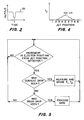
- Figure 4 shows a plot of the digital pulse widths T 2 of Figure 3, Column C, plotted against ejector 1 position. As the ejector 1 moves from left to right, the pulse widths T 2 become wider and then narrower. Using a digital program to fit the curve, the position of the drop 31 in relation to the ejector 1 is computed. Here the droplet is found from analysis of the data to be offset to the right a distance ⁇ x from the preferred droplet 31 position. The program also computes drop velocity from the digital waveshapes of Figure 3, Column C. The droplet velocity is equal to the distance from the ejector 1 to the detection area divided by T 1 plus T 2 /2. That is:
- the ejector controller 17 calculates the correction necessary to correct the change in error ⁇ x by causing the ejector 1 to expel droplets 31 sooner or later than normal operation.
- the droplet is off a distance Ax to the right of where it is supposed to be. Accordingly, when the ejector 1 is printing from left to right, the ejector controller 17, using the ejector position detector signal 29, causes ejector 1 to eject droplets at a position to the left of or before it would normally eject.
- the ejector controller 17 would cause the ejector,4.to eject droplets again further to the left but timewise after it would normally cause droplets to be ejected.
- the calibration cycle would be repeated for each ejector. If each ejector in the array of jets is offset horizontally from each other, then it would be possible to calibrate all jets in a single pass.
- FIG. 5 is a simplified flowchart of the process used in the operation of the apparatus of Figure 1.
- the program waits for a pulse in signal 25. If a pulse is detected, T 1 and T 2 are stored. If no pulse is detected, but a prior droplet was detected,-the prior droplet becomes the last of the series, and the program branches to the curve fitting portion of the program to produce an error determination and, if required, a calibration correction.
- the ejector 1 is scanned by the detection zone 13 at a calibration velocity (V ) less than the print velocity (Vp). Also, the ejector 1 is fired during calibration at a rate such that only a single droplet is in flight between the ejector 1 and the droplet detection zone 13 at a time. This is in order to keep track of data, since one can fire the jet and detect the resultant droplet 31 before the next droplet 31 is ejected.
- the X p is the correction in horizontal droplet placement which must be corrected for by delaying or advancing the time of droplet ejection. In this formula, care must be taken to use the correct mathematical signs, dependent upon the direction of the motion.
Landscapes
- Particle Formation And Scattering Control In Inkjet Printers (AREA)
- Ink Jet (AREA)
Applications Claiming Priority (2)
| Application Number | Priority Date | Filing Date | Title |
|---|---|---|---|
| US06/468,834 US4509057A (en) | 1983-03-28 | 1983-03-28 | Automatic calibration of drop-on-demand ink jet ejector |
| US468834 | 1983-03-28 |
Publications (2)
| Publication Number | Publication Date |
|---|---|
| EP0121304A2 true EP0121304A2 (de) | 1984-10-10 |
| EP0121304A3 EP0121304A3 (de) | 1985-12-18 |
Family
ID=23861433
Family Applications (1)
| Application Number | Title | Priority Date | Filing Date |
|---|---|---|---|
| EP84300844A Withdrawn EP0121304A3 (de) | 1983-03-28 | 1984-02-10 | Selbsttätiges Kalibrieren einer Vorrichtung zur gesteuerten Tröpfchenerzeugung |
Country Status (3)
| Country | Link |
|---|---|
| US (1) | US4509057A (de) |
| EP (1) | EP0121304A3 (de) |
| JP (1) | JPS59214660A (de) |
Cited By (1)
| Publication number | Priority date | Publication date | Assignee | Title |
|---|---|---|---|---|
| US8197022B2 (en) | 2009-09-29 | 2012-06-12 | Eastman Kodak Company | Automated time of flight speed compensation |
Families Citing this family (36)
| Publication number | Priority date | Publication date | Assignee | Title |
|---|---|---|---|---|
| JP2522770B2 (ja) * | 1986-08-05 | 1996-08-07 | キヤノン株式会社 | インクジェット装置 |
| US4872028A (en) * | 1988-03-21 | 1989-10-03 | Hewlett-Packard Company | Thermal-ink-jet print system with drop detector for drive pulse optimization |
| US5109239A (en) * | 1989-01-31 | 1992-04-28 | Hewlett-Packard Company | Inter pen offset determination and compensation in multi-pen ink jet printing systems |
| US4922268A (en) * | 1989-01-31 | 1990-05-01 | Hewlett-Packard Company | Piezoelectric detector for drop position determination in multi-pen thermal ink jet pen printing systems |
| US4922270A (en) * | 1989-01-31 | 1990-05-01 | Hewlett-Packard Company | Inter pen offset determination and compensation in multi-pen thermal ink jet pen printing systems |
| US5160938A (en) * | 1990-08-06 | 1992-11-03 | Iris Graphics, Inc. | Method and means for calibrating an ink jet printer |
| US5646654A (en) * | 1995-03-09 | 1997-07-08 | Hewlett-Packard Company | Ink-jet printing system having acoustic transducer for determining optimum operating energy |
| US5844581A (en) * | 1996-05-25 | 1998-12-01 | Moore Business Forms Inc. | Electronic control for consistent ink jet images |
| US5929875A (en) * | 1996-07-24 | 1999-07-27 | Hewlett-Packard Company | Acoustic and ultrasonic monitoring of inkjet droplets |
| US6227643B1 (en) | 1997-05-20 | 2001-05-08 | Encad, Inc. | Intelligent printer components and printing system |
| JP4003273B2 (ja) * | 1998-01-19 | 2007-11-07 | セイコーエプソン株式会社 | パターン形成方法および基板製造装置 |
| DE60119191T2 (de) * | 2000-02-23 | 2007-04-12 | Seiko Epson Corp. | Detektion einer nicht funktionierenden Düse mittels eines Lichtstrahles durch eine Öffnung |
| AU2002239566A1 (en) * | 2000-11-09 | 2002-05-27 | Therics, Inc. | Method and apparatus for obtaining information about a dispensed fluid during printing |
| US6764156B2 (en) * | 2000-12-12 | 2004-07-20 | Xerox Corporation | Head signature correction in a high resolution printer |
| WO2002055310A1 (en) | 2001-01-09 | 2002-07-18 | Encad, Inc. | Ink jet printhead quality management system and method |
| US6655777B2 (en) * | 2001-07-18 | 2003-12-02 | Lexmark International, Inc. | Automatic horizontal and vertical head-to-head alignment method and sensor for an ink jet printer |
| US6626513B2 (en) | 2001-07-18 | 2003-09-30 | Lexmark International, Inc. | Ink detection circuit and sensor for an ink jet printer |
| US6631971B2 (en) | 2001-07-18 | 2003-10-14 | Lexmark International, Inc. | Inkjet printer and method for use thereof |
| US6616261B2 (en) | 2001-07-18 | 2003-09-09 | Lexmark International, Inc. | Automatic bi-directional alignment method and sensor for an ink jet printer |
| US6843547B2 (en) | 2001-07-18 | 2005-01-18 | Lexmark International, Inc. | Missing nozzle detection method and sensor for an ink jet printer |
| US6897466B2 (en) * | 2001-07-19 | 2005-05-24 | Seiko Epson Corporation | Instrument and method for measuring ejection velocity of liquid |
| US6858860B2 (en) * | 2001-07-24 | 2005-02-22 | Seiko Epson Corporation | Apparatus and method for measuring natural period of liquid |
| US6530640B1 (en) * | 2001-08-29 | 2003-03-11 | Hewlett-Packard Company | Focused ink drop detection |
| US6726318B2 (en) * | 2001-11-30 | 2004-04-27 | Konica Corporation | Microscopic droplet detecting device and ink-jet recording apparatus |
| US6629747B1 (en) | 2002-06-20 | 2003-10-07 | Lexmark International, Inc. | Method for determining ink drop velocity of carrier-mounted printhead |
| JP4107198B2 (ja) * | 2002-11-20 | 2008-06-25 | セイコーエプソン株式会社 | 液滴吐出装置、液滴吐出方法および電気光学装置 |
| US7055925B2 (en) * | 2003-07-31 | 2006-06-06 | Hewlett-Packard Development Company, L.P. | Calibration and measurement techniques for printers |
| JP5008307B2 (ja) * | 2005-02-03 | 2012-08-22 | オセ−テクノロジーズ・ベー・ヴエー | インクジェットプリンタの印刷方法、およびこの方法が適用されるように修正されたインクジェットプリンタ |
| US8251476B2 (en) | 2010-02-03 | 2012-08-28 | Xerox Corporation | Ink drop position correction in the process direction based on ink drop position history |
| US8262190B2 (en) | 2010-05-14 | 2012-09-11 | Xerox Corporation | Method and system for measuring and compensating for process direction artifacts in an optical imaging system in an inkjet printer |
| US8721026B2 (en) | 2010-05-17 | 2014-05-13 | Xerox Corporation | Method for identifying and verifying dash structures as candidates for test patterns and replacement patterns in an inkjet printer |
| US8840223B2 (en) | 2012-11-19 | 2014-09-23 | Xerox Corporation | Compensation for alignment errors in an optical sensor |
| US8764149B1 (en) | 2013-01-17 | 2014-07-01 | Xerox Corporation | System and method for process direction registration of inkjets in a printer operating with a high speed image receiving surface |
| DE102013006106A1 (de) * | 2013-04-09 | 2014-10-09 | Delo Industrie Klebstoffe Gmbh & Co. Kgaa | Dosiervorrichtung |
| EP3233497B1 (de) * | 2015-02-27 | 2021-09-15 | Hewlett-Packard Development Company, L.P. | Tropfgeschwindigkeitsabweichungsnachweis |
| WO2019089036A1 (en) * | 2017-11-02 | 2019-05-09 | Hewlett-Packard Development Company, L.P. | Carriage repositioning |
Family Cites Families (14)
| Publication number | Priority date | Publication date | Assignee | Title |
|---|---|---|---|---|
| US3886564A (en) * | 1973-08-17 | 1975-05-27 | Ibm | Deflection sensors for ink jet printers |
| US3911818A (en) * | 1973-09-04 | 1975-10-14 | Moore Business Forms Inc | Computer controlled ink jet printing |
| US3907429A (en) * | 1974-08-08 | 1975-09-23 | Ibm | Method and device for detecting the velocity of droplets formed from a liquid stream |
| US3911445A (en) * | 1974-09-25 | 1975-10-07 | Dick Co Ab | Ink drop stream integrity checker in an ink jet printer |
| US4045770A (en) * | 1976-11-11 | 1977-08-30 | International Business Machines Corporation | Method and apparatus for adjusting the velocity of ink drops in an ink jet printer |
| CA1085445A (en) * | 1976-12-30 | 1980-09-09 | Lawrence Kuhn | Time correction system for multi-nozzle ink jet printer |
| US4150384A (en) * | 1977-10-17 | 1979-04-17 | International Business Machines Corporation | Method and apparatus for synchronizing charging of droplets of a pressurized conductive liquid stream |
| US4217594A (en) * | 1977-10-17 | 1980-08-12 | International Business Machines Corporation | Method and apparatus for determining the velocity of a liquid stream of droplets |
| US4136345A (en) * | 1977-10-31 | 1979-01-23 | International Business Machines Corporation | Object deflection sensor |
| US4138688A (en) * | 1977-12-23 | 1979-02-06 | International Business Machines Corporation | Method and apparatus for automatically controlling the inclination of patterns in ink jet printers |
| US4255754A (en) * | 1979-03-19 | 1981-03-10 | Xerox Corporation | Differential fiber optic sensing method and apparatus for ink jet recorders |
| US4323908A (en) * | 1980-08-01 | 1982-04-06 | International Business Machines Corp. | Resonant purging of drop-on-demand ink jet print heads |
| US4340893A (en) * | 1980-11-05 | 1982-07-20 | Xerox Corporation | Scanning dryer for ink jet printers |
| US4323905A (en) * | 1980-11-21 | 1982-04-06 | Ncr Corporation | Ink droplet sensing means |
-
1983
- 1983-03-28 US US06/468,834 patent/US4509057A/en not_active Expired - Fee Related
-
1984
- 1984-02-10 EP EP84300844A patent/EP0121304A3/de not_active Withdrawn
- 1984-03-22 JP JP59055930A patent/JPS59214660A/ja active Pending
Cited By (1)
| Publication number | Priority date | Publication date | Assignee | Title |
|---|---|---|---|---|
| US8197022B2 (en) | 2009-09-29 | 2012-06-12 | Eastman Kodak Company | Automated time of flight speed compensation |
Also Published As
| Publication number | Publication date |
|---|---|
| EP0121304A3 (de) | 1985-12-18 |
| JPS59214660A (ja) | 1984-12-04 |
| US4509057A (en) | 1985-04-02 |
Similar Documents
| Publication | Publication Date | Title |
|---|---|---|
| US4509057A (en) | Automatic calibration of drop-on-demand ink jet ejector | |
| US7104634B2 (en) | Ink jet printers and methods | |
| US5534895A (en) | Electronic auto-correction of misaligned segmented printbars | |
| US4328504A (en) | Optical sensing of ink jet printing | |
| JPH0729439B2 (ja) | インクジエツトプリンタ | |
| US20010040599A1 (en) | Easy to make printer and process for embodiment | |
| US4047183A (en) | Method and apparatus for controlling the formation and shape of droplets in an ink jet stream | |
| US6609777B2 (en) | Determination of recording position misalignment adjustment value in main scanning forward and reverse passes | |
| US20110273500A1 (en) | Liquid ejecting apparatus | |
| KR100636480B1 (ko) | 잉크 방울 분사 타이밍 제어 장치 및 방법과, 잉크 젯 용지 형상 보상 장치 | |
| US7621616B2 (en) | Ink jet recording apparatus and method and program for checking nozzles thereof | |
| US7246890B2 (en) | Detection device for detecting ejection condition of nozzles | |
| US20250367923A1 (en) | Ejection apparatus and ejection speed calculation method | |
| US6843548B2 (en) | Ink-jet printer | |
| US6669324B1 (en) | Method and apparatus for optimizing a relationship between fire energy and drop velocity in an imaging device | |
| EP1245397B1 (de) | Vorrichtung und Verfahren zur Tintentropfenerfassung in einem Druckgerät | |
| JP7494007B2 (ja) | 吐出装置及び吐出手段の制御方法 | |
| JPH10217444A (ja) | インクジェット式記録装置 | |
| JP2025118920A (ja) | 吐出装置及び吐出タイミングの決定方法 | |
| JP7700329B2 (ja) | 吐出装置及び吐出タイミングの決定方法 | |
| US11850847B2 (en) | Inkjet printing apparatus and inkjet printing method | |
| US6322184B1 (en) | Method and apparatus for improved swath-to-swath alignment in an inkjet print engine device | |
| JP2024180095A (ja) | 記録装置 | |
| JP2024088387A (ja) | 記録装置 | |
| JPH05254121A (ja) | インクジェット記録装置 |
Legal Events
| Date | Code | Title | Description |
|---|---|---|---|
| PUAI | Public reference made under article 153(3) epc to a published international application that has entered the european phase |
Free format text: ORIGINAL CODE: 0009012 |
|
| AK | Designated contracting states |
Designated state(s): DE GB IT |
|
| PUAL | Search report despatched |
Free format text: ORIGINAL CODE: 0009013 |
|
| AK | Designated contracting states |
Designated state(s): DE GB IT |
|
| STAA | Information on the status of an ep patent application or granted ep patent |
Free format text: STATUS: THE APPLICATION IS DEEMED TO BE WITHDRAWN |
|
| 18D | Application deemed to be withdrawn |
Effective date: 19860819 |
|
| RIN1 | Information on inventor provided before grant (corrected) |
Inventor name: LEICHT, JOHN ROYCE Inventor name: SOHL, GORDON Inventor name: ORT, DONALD LEROY |