EP0121780A1 - Vorrichtung zur Bildung der Knieschenkeloberfläche - Google Patents
Vorrichtung zur Bildung der Knieschenkeloberfläche Download PDFInfo
- Publication number
- EP0121780A1 EP0121780A1 EP84102489A EP84102489A EP0121780A1 EP 0121780 A1 EP0121780 A1 EP 0121780A1 EP 84102489 A EP84102489 A EP 84102489A EP 84102489 A EP84102489 A EP 84102489A EP 0121780 A1 EP0121780 A1 EP 0121780A1
- Authority
- EP
- European Patent Office
- Prior art keywords
- femur
- main body
- guide
- long axis
- central long
- Prior art date
- Legal status (The legal status is an assumption and is not a legal conclusion. Google has not performed a legal analysis and makes no representation as to the accuracy of the status listed.)
- Granted
Links
- 238000007493 shaping process Methods 0.000 title claims abstract description 24
- 210000000689 upper leg Anatomy 0.000 claims abstract description 97
- 238000002271 resection Methods 0.000 claims abstract description 68
- 210000003127 knee Anatomy 0.000 claims description 13
- 238000000034 method Methods 0.000 description 23
- 241001227561 Valgus Species 0.000 description 6
- 210000002303 tibia Anatomy 0.000 description 4
- 238000001356 surgical procedure Methods 0.000 description 3
- 208000006735 Periostitis Diseases 0.000 description 2
- 210000000501 femur body Anatomy 0.000 description 2
- 238000005259 measurement Methods 0.000 description 2
- 239000002184 metal Substances 0.000 description 2
- 229910052751 metal Inorganic materials 0.000 description 2
- 210000003460 periosteum Anatomy 0.000 description 2
- 230000000007 visual effect Effects 0.000 description 2
- 210000001264 anterior cruciate ligament Anatomy 0.000 description 1
- 230000001419 dependent effect Effects 0.000 description 1
- 201000010099 disease Diseases 0.000 description 1
- 208000037265 diseases, disorders, signs and symptoms Diseases 0.000 description 1
- 238000002224 dissection Methods 0.000 description 1
- 210000003414 extremity Anatomy 0.000 description 1
- 230000005021 gait Effects 0.000 description 1
- 230000001771 impaired effect Effects 0.000 description 1
- 239000007943 implant Substances 0.000 description 1
- 238000002513 implantation Methods 0.000 description 1
- 238000013150 knee replacement Methods 0.000 description 1
- 210000002414 leg Anatomy 0.000 description 1
- 150000002739 metals Chemical class 0.000 description 1
- 239000000203 mixture Substances 0.000 description 1
- 210000004417 patella Anatomy 0.000 description 1
- 230000003014 reinforcing effect Effects 0.000 description 1
- 230000000284 resting effect Effects 0.000 description 1
- 229910001220 stainless steel Inorganic materials 0.000 description 1
- 239000010935 stainless steel Substances 0.000 description 1
- 210000001519 tissue Anatomy 0.000 description 1
- 230000000472 traumatic effect Effects 0.000 description 1
Images

Classifications
-
- A—HUMAN NECESSITIES
- A61—MEDICAL OR VETERINARY SCIENCE; HYGIENE
- A61B—DIAGNOSIS; SURGERY; IDENTIFICATION
- A61B17/00—Surgical instruments, devices or methods
- A61B17/14—Surgical saws
- A61B17/15—Guides therefor
- A61B17/154—Guides therefor for preparing bone for knee prosthesis
- A61B17/155—Cutting femur
Definitions
- This invention relates to an apparatus for shaping the distal surface of a human femur using certain alignment guides to guide the shaping of that surface to receive a distal femoral prosthesis.
- the long central axis of the femur as a guide in determining the manner in which the distal femoral surface should be shaped to receive a properly aligned distal femoral prosthesis.
- a pre-operative single, long anterior-posterior radiograph showing the shaft of the tibia and femur is made and the angle of the long central axis of the femur relative to the vertical axis of the body (physiological valgus, generally from 5°-12°) is visualized. That angle is then used as a reference when the distal femoral surface is shaped using various cutting instruments and guides.
- a long axial alignment jig (rod) which is positioned over the outside surface of the patient's leg in a position which the surgeon visually determines to correspond to the central long axis of the femur and the femur is shaped relative to the alignment of that rod.
- a long axial alignment jig (rod) which is positioned over the outside surface of the patient's leg in a position which the surgeon visually determines to correspond to the central long axis of the femur and the femur is shaped relative to the alignment of that rod.
- the external alignment rod has a disadvantage in that the surgeon is relying upon visual and tactile means for positioning the alignment rod and thereby the femoral surface resection guide since the patient's skin covers the major portion of the femur and screens it from view.
- a femoral drill jig having two posterior skids which align with the posterior surfaces of the femoral condyles and a drill bit which is caused to rest in the center of the patello-femoral (intercondylar) groove to obtain correct medial-lateral and rotational positioning of the jig prior to using the jig to bore holes in the femur to receive the fixation studs of a distal femoral prosthesis.
- reference points located directly on the distal femoral surface are employed to position the jig.
- the initial resection of the distal femoral condyles is made using a jig employing an external alignment rod.
- Resection of the anterior and posterior aspects of the distal femoral condyles is accomplished through the use of another jig which has locking studs which are inserted into the fixation stud holes remaining in the femur after the femoral drill jig is removed.
- a method for shaping the distal femoral surface employing the use of a relatively short femoral alignment rod which is positioned in the intramedullary canal is shown in a brochure entitled "New Jersey Tricompartmental Total Knee Replacement Surgical Procedure by Frederick F. Buechel, M.D.”, 13 pages, issue date 1/1981, Form. No.-1280-32, from DePuy Division, Boehringer Mannheim Corporation, Warsaw, Indiana 46580.
- the alignment rods employed may not enable a surgeon to accurately follow the central long axis of the femur because the femur is not exposed to visual observation along its length. This can especially become a problem when the femur possesses a deformity which may somewhat alter its true central long axis.
- One object of the present invention is to provide a means by which certain reproducible reference points for the shaping of the distal femoral surface can be instrumentally located and fixed.
- the problem of the invention is solved by the means according to the claims which results in a method which comprises placing a main body of an alignment guide having a resection guide 5 instrument holder affixed thereto on the anterior surface of the tibia wherein the holder is adjusted to hold a pivotable resection guide instrument at a preselected angle with respect to the central long axis of the main body and of the femur; inserting a locator pin through the ) pivot point of the holder; advancing the main body along the anterior surface of the femur until it contacts the center of the intercondylar notch of the distal femoral condyles; rotating the main body to properly align the central axis of the locator pin transversely with respect to the posterior aspects of the femoral condyles; affixing the main body to the femur; attaching a distal femoral surface shaping guide instrument to the instrument holder; modifying the distal femoral surface through the use of that instrument; attach
- This invention relates to a distal femoral alignment guide which is a combination of a main body, an instrument holder, a locator pin, a distal femoral surface shaping guide and a means for affixing the main body to the femur.
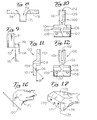
- FIG. 1-3 show the preferred form for the main body 10 of the alignment guide of the present invention.
- Main body 10 contains a pair of positioning fins 11 and 12 which are adapted to rest on the anterior surface of the shaft of the distal femur and in the embodiment shown are 0.5" (12.7 mm)--the symbol " means inches and mm means millimeters--in width at edge 21 appearing in the side view of FIG. 2.
- Arm 13 connects fins 11 and 12 to transverse positioning plate 14.
- plate 14 is 1.47" (37.3 mm) high and 0.25" (6.4 mm) thick having a distance of 0.69" (17.5 mm) between the upper surface of plate 15 and the upper surface of arm 13. Arm 13 is 0.28" (7.1 mm) in thickness.
- plate 14 is 1.87" (47.5 mm) in width.
- Cylindrical guideplate holder 16 extends upward from plateau 15 and is designed to cooperatively engage with the hereinafter described resection instrument guide * of arm holder and in the preferred embodiment shown in 0.497" (12.6 mm) in diameter 0.63" (16 mm) high and has a concentric passage 17 through its center which is transverse to and passes through plateau 15. Passage 17 is adapted to cooperatively engage a locator pin as will be described infra.
- - passage 17 is 0.257" (6.5 mm) in diameter and the center (central long axis) of passage 17 is 0.38" (9.7 mm) from edge 23 of plate 15.
- the preferred main body 10 shown in FIG. 1 is 5.63" (143 mm) in length from a vertical plane defined by the distal edges of fins 11 and 12 to the edge 23 of plateau 15, i.e., along its central long axis.
- four threaded passages 18 and corresponding threaded passages 19 pass through the surface of plateau 15 with the centers of passages 18 and 19 which are closest to holder 16 being a horizontal distance of 1" (25.4 mm) from the central long axis (center) of holder 16, the measurement being taken along the horizontal central long axis of main body 15, and the remainder of passages 18 and 19 are situated a horizontal distance of 1.25", 1.50" and 1.75" (31.8 mm, 38.1 mm and 44.4 mm), respectively, from that axis.
- Each passage is placed on plateau 15 such that when the hereinafter described resection guide instrument holder is affixed to the main body, the holder can be adjusted to hold a resection guide instrument at a fixed angle with respect to the horizontal central long,axis,of the upper portion of main body 10 and thereby to the central long axis of the femur which is caused to run through the horizontal central long axis of the upper portion of the main body 10 by means of the hereinafter described manner in which it is affixed to the distal femur.
- the centers of the closest of passages 18 and 19 to passage 17 are each typically situated 0.0435" (1.10 mm) from the horizontal central long axis of main body 10 while the remaining passages are situated 0.0765", 0.119" and 0.170" (1.94 mm, 3.02 mm and 4.32 mm), respectively, away from the central long axis (center) of holder 16.
- a reinforcing means shown as rib 20 may be fitted between positioning plate 14 and plateau 15 to strengthen and rigidify plateau 15. All measurements specified herein are nominal.
- FIG. 3 shows main body 10 from the front showing the recess 24 in positioning plate 14 which as a configuration similar to fins 11 and 12 and is likewise adapted to rest on the anterior surface of the distal femur to securely affix main body 10 to that surface.
- the recess 21 extends 0 ⁇ .5" (12.7 mm) upward in the center and the sides are set at a 45° angle with respect to a plane running across recess 24 along the bottom edge of positioning plate 14.
- Holder 40 is composed of a locator plate 41 having a raised portion 42 which cooperatively engages guideplate holder 16 of main body 10 by means of passage 44. Passage 44 fits over guideplate holder 16 and allows plate 41 to pivot about the central long axis of guideplate holder 16 to enable resection guide instruments which cooperatively engage with guideplate 43 to be pivoted about the same axis.
- Guideplate 43 is affixed to and forms a part of raised portion 42 and locator place 41.
- passages 47 which are marked with numerals 48 are brought into alignment with passages 18 (for the right femur) and passages 19 (for the left femur as indicated by reference numeral 46).
- a locking bolt or other position fixing means can then be placed through the preselected passage 47 and corresponding appropriate passage 18 or 19 to cause the front surface 49 of guideplate 43 to assume a specific angle (5°, 7°, 9°, 11° or some other preselected angle) with respect to the horizontal central long axis of the main body 10 and thus with respect to the central long axis of the femur to shape the femur to the preselected degree of physiological valgus.
- guideplate 43 is of a suitable configuration which enables a distal femoral surface resection guide to be cooperatively engaged with it such that the distal femoral surface is resected relative to the position of holder 40 to the horizontal central long axis of main body 10.
- guideplate 43 contains passages 45 and 5.0 which are threaded or contain some other means therein to receive a means for fixedly securing a resection guide instrument to guideplate 43.
- passage 44 has a 0.500" (12.7 mm) inner diameter when main body 10 having holder 16 of 0.497" (12.6 mm) outer diameter is employed.
- the centers of passages 47 are located 1.004", 1.259", 1.519" and 1.783" (25.50 mm, 31.98 mm, 38.58 mm and 45.29 mm), respectively, from the center of passage 44.
- the planar surface 49 of guideplate 43 facing shown in FIGS. 5 and 6 is vertically (FIG. 5) parallel to the central long axis of passage 44 and horizontally transverse (FIG.
- locator plate 41 is 0.25" (6.4 mm) in thickness and is 0.375" (9.5 mm) above the lower edge of guideplate 43, raised portion 42 is 0.63" (16 mm) in height and guideplate 43 is 0.38" (9.7 mm) in thickness.
- guideplate 43 shown in 1.5" (38.1 mm) in height and 0.75 " (19.1 mm) in width with passages 45 and 50 being 0.25" (6.4 mm) in diameter and are spaced 1" (25.4 mm) apart.
- FIGS. 7-9 show a preferred embodiment of a distal femoral condyle resection guide instrument 70.
- Instrument 70 has a recessed portion 71 which is adapted to cooperatively engage the front surface 49 and sides of guideplate 43 shown in FIG. 6.
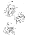
- a locking bolt or other means is passed through slot 72 in portion 71 to secure instrument 70 to holder 40 as shown in FIG. 14.
- Portion 71 has resection guides 75 and 76 attached to it by means of arms 74 and 73, respectively.
- Arms 74 and 73 hold the guide surfaces 77 and 78, respectively of resection guides 75 and 76 at a fixed and preselected distance from and parallel to the central long axis of passage 44.
- guide surfaces 77 and 78 are held in a position which is transverse to the central long axis of main body 10 (not shown).
- the central long axis of passage 44 axis is adapted to be concentric with the central long axis of passage 17 in main body 10, the position of the guide surfaces 77 and 78 of guideplates 75 and 76 which are distal to recessed portion 71 and which are used to guide a resection means such as a saw blade are situated along the distal femoral condyles relative to the position of the central long axis of passage 17.
- a locator pin 129 having handle 131 and having a positioning portion 130 which is adapted to cooperatively engage with passage 17 is passed through passage 17 and main body 10 is moved toward the proximal end of the femur until the rear surface of portion 130 rests in the middle of and against the distal intercondylar notch 135 of ' distal femur 134.
- the guide surfaces 77 and 78 are spaced away from notch 135 a distance equal to the distance between a plane formed by guide surfaces 77 and 78 of guideplates 75 and 76 and the central long axis of passage 17 plus an amount equal to the radius of portion 130 (0.250" (6.35 mm) in diameter when passage 17 is 0.257" (6.53 mm) in diameter) because the central long axis of portion 130 is adapted to be concentric with passage 17.
- the actual distance selected is dependent upon the configuration of the distal femoral prosthesis for which the distal femoral surface is being shaped to receive.
- Instrument 70 enables a surgeon to easily and reproducibly resect the distal femoral condyles of either the right or left femur using the same guide instrument 70 and the resection is always made relative to the distal intercondylar notch and transverse to and at a preselected angle with respect to the central long axis of the femur.
- Another advantage is that the alignment guide is noninvasive, i.e., it is not affixed to the femur by boring holes or by using other fixation means which extend through the surface of the femur.
- FIGS. 10-12 show a preferred embodiment of an anterior-posterior condyle resection guide instrument 100 which contains a recessed portion 101 which is adapted to cooperatively engage the front surface 49 and sides of guideplate 43 of FIG. 6.
- a locking bolt or other means is passed through slot 102 to holder 40 as shown in FIG. 15.
- Recessed portion 101 functions in the same manner as does the previously described recessed portion 71 of instrument 70.
- portion 101 further includes passage 103 which is also adapted to cooperatively engage a locator pin 129 having positioning portion 130 as shown in FIG.
- the distance between the lower surface of portion 103 and the upper surface of guideplate 104 is selected to suit the requirements of the distal femoral prosthesis for which the distal femoral surface is being shaped to receive because the upper surfaces of guideplate 104 located on either side of portion 101 are employed as resection guide surfaces upon which a resection means such as a saw blade is placed to accomplish resection of the anterior aspects of the medial and lateral femoral condyles.
- the lower surface of guideplate 104 is likewise located at a preselected distance from the lower surface of positioning portion 130 which suits the requirements of the distal femoral prosthesis selected and those lower surfaces are used to guide a resection means in resecting the posterior aspects of the medial and lateral femoral condyles.
- the rear surface of guideplate 104 is parallel to the central long axis of passage 17 of main body 10 and is thus transverse to the central long axis of the main body 10 and of the femur.
- Bevel cutting guides 105 and 106 are located in guideplate 104 in such a manner that the anterior distal femoral aspects of the femoral condyles are resected at an angle 9 as shown in FIG. 11.
- angle 9 is 45° with respect to an extension of slot 106 and the rear surface of guideplate 104.
- the location of slots 105 and 106 relative to the lower surface (contacting the femur) of positioning portion 130 as well as the angle 9 will be dictated by the type of distal femoral prosthesis selected to be affixed to the distal femoral surface.
- Passages 107 and 108 act as guides for the boring of holes in the distal femoral surface to receive distal femoral prosthesis fixation studs which are used to hold the selected distal femoral prosthesis to the femur and their location on guideplate 104 is likewise dictated by the prosthesis selected. It is another advantage of the present invention that instrument 100 and the other apparatus described herein can be used to shape the distal femoral surface of both the left and the right femur.
- Distal femoral prostheses are well known to those skilled in the art as shown in the previously noted Howmedica, Inc. brochure and no specific details as to their design are included herein. It is well within the ability of those skilled in the art to construct guide instruments in accordance with the aforementioned description which meet the specific design requirements to produce a shaped distal femoral surface for a particular distal femoral prosthesis.
- the above described main body, locator plate, resection instruments and components thereof are all preferably manufactured from a suitable surgical grade of stainless steel of the type commonly employed by those skilled in the art to construct surgical tools for use in contact with the body.
- the exact composition of the metal from which the above are constructed forms no part of the present invention and other metals suitable for use within the body and for the intended uses of the instruments may be used without altering the nature of the invention.
- the extremity is prepared and draped in the usual manner.
- An anterior 5 w to 6" (127 mm to 152 mm) midline incision is made with the knee flexed to 90 degrees.
- the knee is then placed in extension and dissection is carried out in line with the skin incision down through the medial retinaculum.
- Subperiosteal flaps are developed medially and laterally about the metaphyseal flares.
- the patella is reflected laterally and the knee is flexed to 90 degrees.
- the anterior portion of the menisci are excised and the anterior cruciate ligament is incised.
- the proximal tibial surface may preferably now be shaped to receive that proximal tibial prosthesis in the manner typically employed for such a prosthesis.
- the tibial surface should be prepared such that the tibial prosthesis will properly align and cooperate with the distal femoral prosthesis which is attached to the distal femoral surface being shaped in accordance with the method of the present invention.
- the knee is placed in extension and a "T" incision is made in the synovial recess off the anterior femur.
- a plane is developed between the soft areolar tissue and the periosteum. Care should be taken not to strip the periosteum from the anterior portion of the femur.
- Locator 40 is cooperatively engaged with main body 10 by inserting holder 16 through passage 44 and locking bolt 133 is passed through the appropriate passage in locator plate 41 corresponding to the desired degree of valgus radiographically determined to be needed for the patient. Typically, an angle of 5°, 7°, 9° or 11° will suffice with 9° being the most commonly used degree of valgus.
- Locator plate 41 is rotated about holder 16 until the correct passage (18 for the right and 19 for the left femur) in main body 10 lines up with passage 44 and locking bolt 133 is passed into passage 18 or 19 to fix locator 40 to main body 10.
- Positioning portion 130 of locator pin 129 is placed through passage 17 in main body 10 and main body 10 is then inserted along the anterior shaft of the femur with fins 11 and 12 resting along that shaft until positioning portion 130 contacts the distal intracondylar notch 135 and main body 10 cannot be inserted any further.
- the central long axis of positioning portion 130 should then be aligned perpendicular to a plane defined by the posterior aspects of the medial and lateral femoral condyles by moving main body 10 from side to side until it is aligned as above. Generally, if there is no angular deformity in the distal femoral surface, the central long axis of positioning will point down the shaft of the tibia.
- the alignment may be checked by placing a straight edge transversely along the posterior surfaces of the femoral condyles to insure that the central long axis of positioning portion 130 is perpendicular to'the plane defined by the posterior surfaces of the femoral condyles. This positioning determines the proper rotational alignment for the distal femoral prosthesis to be attached.
- Main body 10 with locator 40 attached thereto is then securely fixed to the distal femur 134 by some suitable means such as clamp 136.
- locator pin 129 is shown above passage 17 for the purposes of clarity.
- Locking bolt 132 which is employed to secure resection guide instruments to guideplate 43 is shown in exploded fashion set away from passage 50. For some distal femoral surfaces, it may be more desirable to place locking bolt 132 in passage 45 instead of passage 50.
- distal femoral condyle resection guide instrument 70 is cooperatively engaged with guideplate 43 of locator 40 and lowered until the arms 73 and 74 rest on the anterior surfaces of the distal femoral condyles and secured to guideplate 43 by means of locking bolt 132.
- a resection means such as an oscillating saw (not shown) is placed against the distal surface of guide 76 and the saw is brought across the guide 76 in the direction of arrows 142 to transversely reset the distal femoral condyle.
- the same procedure is repeated for the opposite distal condylar surface using guide 75 to guide a resection means in the direction of arrows 142.
- Instrument 70 is then removed and the resection of each distal condylar surface is completed if it could not be completed with instrument 70 in place.
- the resulting resected distal femoral surface is transverse to the central long axis of the femur and offset from that axis-by the preselected angle of physiological valgus.
- anterior-posterior condyle resection guide instrument 100 placed on guideplate 43 and locking bolt 132 is loosely placed in passage 50 such that instrument 100 can slide up and down on guideplate 43 in the direction of the arrows.
- the prosthesis selected and thus the size of the guideplate 104 of instrument 100 selected should be as large as possible consistent with the size of the distal femur such that the prosthesis to be implanted will provide stability with the knee in flexion.
- Positioning portion 130 of locating pin,129 is inserted into passage 103 and instrument 100 is lowered until the lower surface of portion 130 contacts the anterior surface of the femur located in the intercondylar notch 150 located between the anterior aspects of the lateral and medial distal femoral condyles.
- the upper surface of guideplate 104 is located relative to the lower surface of portion 130 such that when portion 130 touches the intercondylar notch 150, the upper surface of guideplate 104 is parallel to the apex of the anterior surface of the shaft of the femur 134.
- Resection of the distal femoral surface using instrument 100 is accomplished by using the upper surface of guideplate 104 as a guide for transversely resecting the anterior aspects of the distal femoral condyles and the lower edge of guideplate 104 is employed as a guide for transversely resecting the posterior aspects of the distal femoral condyles in the direction of arrows 151 and 152.
- the anterior distal femoral surface is bevelled by placing a resection means in each of the bevelled slots 105 and 106 using the anterior bevelled surface of each slot as a resection guide surface.
- Fixation stud holes are drilled in the distal femoral surface using holes 107 and 108 in guideplate 104 as a guide. Instrument 100 is removed and any resections which could not be completed with instrument 100 in place are completed. Main body 10 and locator 40 are removed from the femur by releasing clamp 136.
- FIG. 16 shows the appearance of distal femur 134 and further shows the last step of bevelling the posterior surface at a preselected angle which is suitable for the distal femoral prosthesis selected.
- oscillating saw blade 160 is employed to bevel the posterior aspect of distal femur 134 at a 45° angle relative to with respect to the distal surface of the femur which is transverse to the central long axis of the femur.
- FIGS. 16 and 17 For purposes of clarity, only the femur is shown in FIGS. 16 and 17.
- FIG. 17 is a perspective view of distal femur 134 which has been shaped in accordance with the method of the present invention. Fixation stud holes 170 and 171 are shown located on the distal femoral surface with the anterior aspect of distal femur 134 shown by reference numeral 172. Bevelled surface 173 is the result of the procedure depicted in FIG. 16.
- the preselected distal femoral prosthesis (not shown) and, if one is to be implanted, an appropriate proximal tibial prosthesis can then affixed in accordance with methods known to those skilled in the art.
- the wound is then closed in the usual fashion employed during the implantation of such prostheses.
- the use of the means according to the invention results in a method of preparing a human femur having a distal femoral surface containing medial and lateral condyles to receive a distal femoral knee prosthesis, said method comprising the steps of
- This method includes that at least one of the shaping guide instruments employed in step (F) is a distal femoral condyle resection guide instrument comprising a recessed portion which is adapted to cooperatively engage said guide means of the holder and maintain said guide in proper alignment with respect to said holder, said guide having a plurality of resection guides for transversely resecting the distal femoral surfaces of the medial and lateral condyles, each of said resection guides being attached to said recessed portion by means of an interconnecting arm, said guides being held transversely to the central long axis of said main body and the femur and further being held at a fixed distance from the intercondylar notch of the femur by means of the position of said main body with respect to said locator pin.
- This method further includes that at least one of the shaping guide instruments of said (F) is an anterior-posterior condyle resection guide instrument which comprises a plate having an upper resection guide i surface for a resecting means used to resect the anterior aspects of the femoral condyles, a lower resection guide surface for a resecting means used to resect the posterior aspect of the femoral condyles, and a bevel resection guide surface for a resecting means used to resect the ) medial and lateral distal condyles at a preselected angle, all of said guide surfaces being adapted to resect said distal femoral surface relative to the central long axis of the main body and of the femur, said plate having a recessed portion attached thereto for cooperatively engaging said holder and maintaining said plate in a fixed relationship with respect to the main body, said instrument further having a means located near the upper resection guide surface for receiving said
Landscapes
- Health & Medical Sciences (AREA)
- Surgery (AREA)
- Life Sciences & Earth Sciences (AREA)
- Biomedical Technology (AREA)
- Medical Informatics (AREA)
- Oral & Maxillofacial Surgery (AREA)
- Nuclear Medicine, Radiotherapy & Molecular Imaging (AREA)
- Transplantation (AREA)
- Physical Education & Sports Medicine (AREA)
- Engineering & Computer Science (AREA)
- Orthopedic Medicine & Surgery (AREA)
- Heart & Thoracic Surgery (AREA)
- Dentistry (AREA)
- Molecular Biology (AREA)
- Animal Behavior & Ethology (AREA)
- General Health & Medical Sciences (AREA)
- Public Health (AREA)
- Veterinary Medicine (AREA)
- Prostheses (AREA)
- Surgical Instruments (AREA)
Applications Claiming Priority (2)
| Application Number | Priority Date | Filing Date | Title |
|---|---|---|---|
| US473466 | 1974-05-28 | ||
| US06/473,466 US4502483A (en) | 1983-03-09 | 1983-03-09 | Method and apparatus for shaping a distal femoral surface |
Publications (2)
| Publication Number | Publication Date |
|---|---|
| EP0121780A1 true EP0121780A1 (de) | 1984-10-17 |
| EP0121780B1 EP0121780B1 (de) | 1987-07-29 |
Family
ID=23879639
Family Applications (1)
| Application Number | Title | Priority Date | Filing Date |
|---|---|---|---|
| EP84102489A Expired EP0121780B1 (de) | 1983-03-09 | 1984-03-08 | Vorrichtung zur Bildung der Knieschenkeloberfläche |
Country Status (4)
| Country | Link |
|---|---|
| US (1) | US4502483A (de) |
| EP (1) | EP0121780B1 (de) |
| CA (1) | CA1211330A (de) |
| DE (1) | DE3465010D1 (de) |
Cited By (7)
| Publication number | Priority date | Publication date | Assignee | Title |
|---|---|---|---|---|
| WO1987002883A1 (fr) * | 1985-11-15 | 1987-05-21 | Jean Manuel Aubaniac | Appareillage pour la pose d'une endo prothese du genou |
| WO1988004912A3 (en) * | 1986-12-24 | 1988-07-28 | Orthomet Inc | Bone cutting guide and methods for using same |
| WO1990001299A1 (en) * | 1988-07-29 | 1990-02-22 | Gregory James Roger | Further improved method and apparatus for removing prosthetic cement |
| FR2635675A1 (fr) * | 1988-08-23 | 1990-03-02 | Laboureau Jacques Philippe | Instrumentation ancillaire pour l'implantation d'une prothese totale du genou et secondairement pour osteotomies de correction axiale |
| FR2648699A1 (fr) * | 1989-06-26 | 1990-12-28 | Matco | Viseur polyvalent pour prothese totale du genou a glissement |
| US5415662A (en) * | 1992-02-20 | 1995-05-16 | Wright Medical Technology, Inc. | Modular shaping and trial reduction guide for implantation of posterior-stabilized femoral prosthesis and method of using same |
| US8523870B2 (en) | 2009-08-20 | 2013-09-03 | Wright Medical Technology, Inc. | Adjustable femoral resection guide |
Families Citing this family (48)
| Publication number | Priority date | Publication date | Assignee | Title |
|---|---|---|---|---|
| US4738253A (en) * | 1981-12-31 | 1988-04-19 | Biomedical Engineering Trust | Guides for inclined surgical cuts or resections |
| US4738254A (en) * | 1981-12-31 | 1988-04-19 | Biomedical Engineering Trust | Positioner for surgical instruments |
| US4825857A (en) * | 1982-02-18 | 1989-05-02 | Howmedica, Inc. | Prosthetic knee implantation |
| US4565191A (en) * | 1984-01-12 | 1986-01-21 | Slocum D Barclay | Apparatus and method for performing cuneiform osteotomy |
| US4636217A (en) * | 1985-04-23 | 1987-01-13 | Regents Of The University Of Minnesota | Anterior spinal implant |
| DE3644624A1 (de) * | 1985-12-27 | 1987-07-02 | Toshiba Kk | Mikrofilm lese-druckgeraet |
| US4703751A (en) * | 1986-03-27 | 1987-11-03 | Pohl Kenneth P | Method and apparatus for resecting a distal femoral surface |
| US4722330A (en) * | 1986-04-22 | 1988-02-02 | Dow Corning Wright Corporation | Femoral surface shaping guide for knee implants |
| US4907578A (en) * | 1986-07-23 | 1990-03-13 | Petersen Thomas D | Method and instruments for resection of the distal femur |
| US5002547A (en) * | 1987-02-07 | 1991-03-26 | Pfizer Hospital Products Group, Inc. | Apparatus for knee prosthesis |
| US5122144A (en) * | 1989-09-26 | 1992-06-16 | Kirschner Medical Corporation | Method and instrumentation for unicompartmental total knee arthroplasty |
| US5171244A (en) * | 1990-01-08 | 1992-12-15 | Caspari Richard B | Methods and apparatus for arthroscopic prosthetic knee replacement |
| GB9202561D0 (en) * | 1992-02-07 | 1992-03-25 | Howmedica | Orthopaedic instrument |
| US5258032A (en) | 1992-04-03 | 1993-11-02 | Bertin Kim C | Knee prosthesis provisional apparatus and resection guide and method of use in knee replacement surgery |
| US5423822A (en) * | 1993-01-27 | 1995-06-13 | Biomet, Inc. | Method and apparatus for preparing a bone for receiving a prosthetic device |
| US8603095B2 (en) | 1994-09-02 | 2013-12-10 | Puget Bio Ventures LLC | Apparatuses for femoral and tibial resection |
| US6695848B2 (en) | 1994-09-02 | 2004-02-24 | Hudson Surgical Design, Inc. | Methods for femoral and tibial resection |
| US5667510A (en) * | 1995-08-03 | 1997-09-16 | Combs; C. Robert | Joint fixation system and method |
| US5830216A (en) * | 1996-10-30 | 1998-11-03 | Bristol-Myers Squibb Company | Apparatus and method for knee implantation |
| US7302288B1 (en) | 1996-11-25 | 2007-11-27 | Z-Kat, Inc. | Tool position indicator |
| US8545569B2 (en) | 2001-05-25 | 2013-10-01 | Conformis, Inc. | Patient selectable knee arthroplasty devices |
| US9603711B2 (en) | 2001-05-25 | 2017-03-28 | Conformis, Inc. | Patient-adapted and improved articular implants, designs and related guide tools |
| US7635390B1 (en) | 2000-01-14 | 2009-12-22 | Marctec, Llc | Joint replacement component having a modular articulating surface |
| US6558391B2 (en) | 2000-12-23 | 2003-05-06 | Stryker Technologies Corporation | Methods and tools for femoral resection in primary knee surgery |
| US7909831B2 (en) | 2001-02-28 | 2011-03-22 | Howmedica Osteonics Corp. | Systems used in performing femoral and tibial resection in knee surgery |
| US6595997B2 (en) | 2001-02-28 | 2003-07-22 | Howmedica Osteonics Corp. | Methods used in performing femoral and tibial resection in knee surgery |
| US6685711B2 (en) | 2001-02-28 | 2004-02-03 | Howmedica Osteonics Corp. | Apparatus used in performing femoral and tibial resection in knee surgery |
| US8062377B2 (en) | 2001-03-05 | 2011-11-22 | Hudson Surgical Design, Inc. | Methods and apparatus for knee arthroplasty |
| US7708741B1 (en) | 2001-08-28 | 2010-05-04 | Marctec, Llc | Method of preparing bones for knee replacement surgery |
| US7618421B2 (en) | 2001-10-10 | 2009-11-17 | Howmedica Osteonics Corp. | Tools for femoral resection in knee surgery |
| US7141053B2 (en) * | 2001-11-28 | 2006-11-28 | Wright Medical Technology, Inc. | Methods of minimally invasive unicompartmental knee replacement |
| WO2003045256A2 (en) * | 2001-11-28 | 2003-06-05 | Wright Medical Technology, Inc. | Instrumentation for minimally invasive unicompartmental knee replacement |
| US8114083B2 (en) * | 2004-01-14 | 2012-02-14 | Hudson Surgical Design, Inc. | Methods and apparatus for improved drilling and milling tools for resection |
| US20060030854A1 (en) * | 2004-02-02 | 2006-02-09 | Haines Timothy G | Methods and apparatus for wireplasty bone resection |
| US7857814B2 (en) * | 2004-01-14 | 2010-12-28 | Hudson Surgical Design, Inc. | Methods and apparatus for minimally invasive arthroplasty |
| US7815645B2 (en) * | 2004-01-14 | 2010-10-19 | Hudson Surgical Design, Inc. | Methods and apparatus for pinplasty bone resection |
| US8021368B2 (en) * | 2004-01-14 | 2011-09-20 | Hudson Surgical Design, Inc. | Methods and apparatus for improved cutting tools for resection |
| US20060030855A1 (en) * | 2004-03-08 | 2006-02-09 | Haines Timothy G | Methods and apparatus for improved profile based resection |
| US7736367B2 (en) * | 2004-06-03 | 2010-06-15 | Howmedica Osteonics Corp. | Ribbed femoral cutting guide |
| EP2649951A3 (de) | 2006-02-06 | 2013-12-25 | ConforMIS, Inc. | Vom Patienten auswählbare Gelenkarthroplastie-Vorrichtungen und chirurgische Instrumente |
| US7678115B2 (en) * | 2006-06-21 | 2010-03-16 | Howmedia Osteonics Corp. | Unicondylar knee implants and insertion methods therefor |
| US8313530B2 (en) * | 2007-02-12 | 2012-11-20 | Jmea Corporation | Total knee arthroplasty system |
| GB2447702A (en) | 2007-03-23 | 2008-09-24 | Univ Leeds | Surgical bone cutting template |
| US8403935B2 (en) * | 2009-11-10 | 2013-03-26 | Wright Medical Technology, Inc. | Adjustable revision guide |
| AU2012273645B2 (en) | 2011-06-22 | 2016-11-17 | Medacta International S.A. | Device for patellar resurfacing |
| US9486226B2 (en) | 2012-04-18 | 2016-11-08 | Conformis, Inc. | Tibial guides, tools, and techniques for resecting the tibial plateau |
| US9675471B2 (en) | 2012-06-11 | 2017-06-13 | Conformis, Inc. | Devices, techniques and methods for assessing joint spacing, balancing soft tissues and obtaining desired kinematics for joint implant components |
| CN103735302A (zh) * | 2013-12-31 | 2014-04-23 | 张文涛 | 一种截骨导向板 |
Citations (1)
| Publication number | Priority date | Publication date | Assignee | Title |
|---|---|---|---|---|
| US4409973A (en) * | 1981-01-29 | 1983-10-18 | Neufeld John A | Method and apparatus for corrective osteotomy |
Family Cites Families (3)
| Publication number | Priority date | Publication date | Assignee | Title |
|---|---|---|---|---|
| US4211228A (en) * | 1979-01-24 | 1980-07-08 | Cloutier Jean Marie | Multipurpose tibial template |
| US4349018A (en) * | 1980-12-29 | 1982-09-14 | Chambers Gary R | Osteotomy apparatus |
| US4457307A (en) * | 1982-08-20 | 1984-07-03 | Stillwell William T | Bone cutting device for total knee replacement |
-
1983
- 1983-03-09 US US06/473,466 patent/US4502483A/en not_active Expired - Lifetime
-
1984
- 1984-02-02 CA CA000446634A patent/CA1211330A/en not_active Expired
- 1984-03-08 DE DE8484102489T patent/DE3465010D1/de not_active Expired
- 1984-03-08 EP EP84102489A patent/EP0121780B1/de not_active Expired
Patent Citations (1)
| Publication number | Priority date | Publication date | Assignee | Title |
|---|---|---|---|---|
| US4409973A (en) * | 1981-01-29 | 1983-10-18 | Neufeld John A | Method and apparatus for corrective osteotomy |
Non-Patent Citations (1)
| Title |
|---|
| JOURNAL OF BONE AND JOINT SURGERY, vol. 65-a, no. 3, March 1983, pages 293-309, Journal of Bone and Joint Surgery, Inc., Boston, Massachusetts, US; N.S. EFTEKHAR et al.: "Total knee-replacement arthroplasty" * |
Cited By (10)
| Publication number | Priority date | Publication date | Assignee | Title |
|---|---|---|---|---|
| WO1987002883A1 (fr) * | 1985-11-15 | 1987-05-21 | Jean Manuel Aubaniac | Appareillage pour la pose d'une endo prothese du genou |
| FR2590159A1 (fr) * | 1985-11-15 | 1987-05-22 | Aubaniac Jean | Appareillage pour la mise en place de protheses du genou notamment mono-compartimentaires internes et/ou externes, trochleo-condyliennes internes ou externes |
| WO1988004912A3 (en) * | 1986-12-24 | 1988-07-28 | Orthomet Inc | Bone cutting guide and methods for using same |
| WO1990001299A1 (en) * | 1988-07-29 | 1990-02-22 | Gregory James Roger | Further improved method and apparatus for removing prosthetic cement |
| US5171277A (en) * | 1988-07-29 | 1992-12-15 | Roger Gregory J | Method and apparatus for removing prosthetic cement |
| FR2635675A1 (fr) * | 1988-08-23 | 1990-03-02 | Laboureau Jacques Philippe | Instrumentation ancillaire pour l'implantation d'une prothese totale du genou et secondairement pour osteotomies de correction axiale |
| FR2648699A1 (fr) * | 1989-06-26 | 1990-12-28 | Matco | Viseur polyvalent pour prothese totale du genou a glissement |
| US5415662A (en) * | 1992-02-20 | 1995-05-16 | Wright Medical Technology, Inc. | Modular shaping and trial reduction guide for implantation of posterior-stabilized femoral prosthesis and method of using same |
| US8523870B2 (en) | 2009-08-20 | 2013-09-03 | Wright Medical Technology, Inc. | Adjustable femoral resection guide |
| US8828015B2 (en) | 2009-08-20 | 2014-09-09 | Microport Orthopedics Holdings Inc. | Adjustable femoral resection guide |
Also Published As
| Publication number | Publication date |
|---|---|
| CA1211330A (en) | 1986-09-16 |
| DE3465010D1 (en) | 1987-09-03 |
| US4502483A (en) | 1985-03-05 |
| EP0121780B1 (de) | 1987-07-29 |
Similar Documents
| Publication | Publication Date | Title |
|---|---|---|
| EP0121780B1 (de) | Vorrichtung zur Bildung der Knieschenkeloberfläche | |
| EP0121142B1 (de) | Vorrichtung zur Bildung der Knieschenkeloberfläche | |
| US4467801A (en) | Method and apparatus for shaping a proximal tibial surface | |
| EP0378294B1 (de) | Femurkopf-Osteomielehre für Kniegelenksimplantate | |
| EP0243109B1 (de) | Femurkopf-Osteotomielehre für Kniegelenkimplantate | |
| US5702460A (en) | Revision femoral trial prosthesis | |
| US6558391B2 (en) | Methods and tools for femoral resection in primary knee surgery | |
| JP3858201B2 (ja) | 遠位大腿サイズ測定の機器 | |
| US4567885A (en) | Triplanar knee resection system | |
| US4349018A (en) | Osteotomy apparatus | |
| US4718413A (en) | Bone cutting guide and methods for using same | |
| US6013081A (en) | Apparatus and method for anterior and posterior referenced sizing and distal femur resection | |
| US5683398A (en) | Distal femoral cutting block assembly | |
| US4759350A (en) | Instruments for shaping distal femoral and proximal tibial surfaces | |
| US4487203A (en) | Triplanar knee resection method | |
| AU696251B2 (en) | Distal femoral cutting guide | |
| US5720752A (en) | Distal femoral cutting guide apparatus with anterior or posterior referencing for use in knee joint replacement surgery | |
| EP0384562B1 (de) | Lehre zur Formung der Tibiaoberfläche für Kniegelenks-Endoprothese | |
| US9078669B2 (en) | Orthopaedic cutting guide instrument | |
| EP0555003A1 (de) | Orthopädische Einrichtung | |
| JPS59200643A (ja) | 大腿骨頚部切断用ガイドおよびその製造方法 | |
| EP0971638A4 (de) | Verfahren und vorrichtung zur femoral-resektion | |
| WO1998032384A9 (en) | Method and apparatus for femoral resection | |
| EP3784150A1 (de) | Schneid- und bohrschablone für unikondyläre kniearthroplastik | |
| JP2004537368A (ja) | 大腿骨切除平面の位置を定めるガイド |
Legal Events
| Date | Code | Title | Description |
|---|---|---|---|
| PUAI | Public reference made under article 153(3) epc to a published international application that has entered the european phase |
Free format text: ORIGINAL CODE: 0009012 |
|
| AK | Designated contracting states |
Designated state(s): CH DE FR GB IT LI |
|
| 17P | Request for examination filed |
Effective date: 19850312 |
|
| 17Q | First examination report despatched |
Effective date: 19860509 |
|
| GRAA | (expected) grant |
Free format text: ORIGINAL CODE: 0009210 |
|
| AK | Designated contracting states |
Kind code of ref document: B1 Designated state(s): CH DE FR GB IT LI |
|
| REF | Corresponds to: |
Ref document number: 3465010 Country of ref document: DE Date of ref document: 19870903 |
|
| ET | Fr: translation filed | ||
| ITF | It: translation for a ep patent filed | ||
| PLBE | No opposition filed within time limit |
Free format text: ORIGINAL CODE: 0009261 |
|
| STAA | Information on the status of an ep patent application or granted ep patent |
Free format text: STATUS: NO OPPOSITION FILED WITHIN TIME LIMIT |
|
| 26N | No opposition filed | ||
| ITTA | It: last paid annual fee | ||
| REG | Reference to a national code |
Ref country code: CH Ref legal event code: PUE Owner name: WRIGHT MEDICAL TECHNOLOGY, INC. |
|
| ITPR | It: changes in ownership of a european patent |
Owner name: CESSIONE;WRIGHT MEDICAL TECHNOLOGY INC. |
|
| REG | Reference to a national code |
Ref country code: GB Ref legal event code: 732E |
|
| REG | Reference to a national code |
Ref country code: FR Ref legal event code: TP |
|
| PGFP | Annual fee paid to national office [announced via postgrant information from national office to epo] |
Ref country code: CH Payment date: 19960220 Year of fee payment: 13 |
|
| PGFP | Annual fee paid to national office [announced via postgrant information from national office to epo] |
Ref country code: FR Payment date: 19960221 Year of fee payment: 13 |
|
| PGFP | Annual fee paid to national office [announced via postgrant information from national office to epo] |
Ref country code: GB Payment date: 19960229 Year of fee payment: 13 |
|
| PGFP | Annual fee paid to national office [announced via postgrant information from national office to epo] |
Ref country code: DE Payment date: 19960319 Year of fee payment: 13 |
|
| PG25 | Lapsed in a contracting state [announced via postgrant information from national office to epo] |
Ref country code: GB Effective date: 19970308 |
|
| PG25 | Lapsed in a contracting state [announced via postgrant information from national office to epo] |
Ref country code: LI Effective date: 19970331 Ref country code: CH Effective date: 19970331 |
|
| GBPC | Gb: european patent ceased through non-payment of renewal fee |
Effective date: 19970308 |
|
| REG | Reference to a national code |
Ref country code: CH Ref legal event code: PL |
|
| PG25 | Lapsed in a contracting state [announced via postgrant information from national office to epo] |
Ref country code: FR Free format text: LAPSE BECAUSE OF NON-PAYMENT OF DUE FEES Effective date: 19971128 |
|
| PG25 | Lapsed in a contracting state [announced via postgrant information from national office to epo] |
Ref country code: DE Effective date: 19971202 |
|
| REG | Reference to a national code |
Ref country code: FR Ref legal event code: ST |