EP0121877A2 - Buse de pulvérisation en forme d'un cône creux - Google Patents
Buse de pulvérisation en forme d'un cône creux Download PDFInfo
- Publication number
- EP0121877A2 EP0121877A2 EP84103521A EP84103521A EP0121877A2 EP 0121877 A2 EP0121877 A2 EP 0121877A2 EP 84103521 A EP84103521 A EP 84103521A EP 84103521 A EP84103521 A EP 84103521A EP 0121877 A2 EP0121877 A2 EP 0121877A2
- Authority
- EP
- European Patent Office
- Prior art keywords
- nozzle
- mixing chamber
- hollow cone
- inlet
- liquid
- Prior art date
- Legal status (The legal status is an assumption and is not a legal conclusion. Google has not performed a legal analysis and makes no representation as to the accuracy of the status listed.)
- Granted
Links
Images

Classifications
-
- B—PERFORMING OPERATIONS; TRANSPORTING
- B05—SPRAYING OR ATOMISING IN GENERAL; APPLYING FLUENT MATERIALS TO SURFACES, IN GENERAL
- B05B—SPRAYING APPARATUS; ATOMISING APPARATUS; NOZZLES
- B05B1/00—Nozzles, spray heads or other outlets, with or without auxiliary devices such as valves, heating means
- B05B1/34—Nozzles, spray heads or other outlets, with or without auxiliary devices such as valves, heating means designed to influence the nature of flow of the liquid or other fluent material, e.g. to produce swirl
- B05B1/3405—Nozzles, spray heads or other outlets, with or without auxiliary devices such as valves, heating means designed to influence the nature of flow of the liquid or other fluent material, e.g. to produce swirl to produce swirl
- B05B1/341—Nozzles, spray heads or other outlets, with or without auxiliary devices such as valves, heating means designed to influence the nature of flow of the liquid or other fluent material, e.g. to produce swirl to produce swirl before discharging the liquid or other fluent material, e.g. in a swirl chamber upstream the spray outlet
- B05B1/3478—Nozzles, spray heads or other outlets, with or without auxiliary devices such as valves, heating means designed to influence the nature of flow of the liquid or other fluent material, e.g. to produce swirl to produce swirl before discharging the liquid or other fluent material, e.g. in a swirl chamber upstream the spray outlet the liquid flowing at least two different courses before reaching the swirl chamber
-
- B—PERFORMING OPERATIONS; TRANSPORTING
- B05—SPRAYING OR ATOMISING IN GENERAL; APPLYING FLUENT MATERIALS TO SURFACES, IN GENERAL
- B05B—SPRAYING APPARATUS; ATOMISING APPARATUS; NOZZLES
- B05B1/00—Nozzles, spray heads or other outlets, with or without auxiliary devices such as valves, heating means
- B05B1/34—Nozzles, spray heads or other outlets, with or without auxiliary devices such as valves, heating means designed to influence the nature of flow of the liquid or other fluent material, e.g. to produce swirl
- B05B1/3405—Nozzles, spray heads or other outlets, with or without auxiliary devices such as valves, heating means designed to influence the nature of flow of the liquid or other fluent material, e.g. to produce swirl to produce swirl
- B05B1/341—Nozzles, spray heads or other outlets, with or without auxiliary devices such as valves, heating means designed to influence the nature of flow of the liquid or other fluent material, e.g. to produce swirl to produce swirl before discharging the liquid or other fluent material, e.g. in a swirl chamber upstream the spray outlet
- B05B1/3421—Nozzles, spray heads or other outlets, with or without auxiliary devices such as valves, heating means designed to influence the nature of flow of the liquid or other fluent material, e.g. to produce swirl to produce swirl before discharging the liquid or other fluent material, e.g. in a swirl chamber upstream the spray outlet with channels emerging substantially tangentially in the swirl chamber
- B05B1/3426—Nozzles, spray heads or other outlets, with or without auxiliary devices such as valves, heating means designed to influence the nature of flow of the liquid or other fluent material, e.g. to produce swirl to produce swirl before discharging the liquid or other fluent material, e.g. in a swirl chamber upstream the spray outlet with channels emerging substantially tangentially in the swirl chamber the channels emerging in the swirl chamber perpendicularly to the outlet axis
-
- B—PERFORMING OPERATIONS; TRANSPORTING
- B05—SPRAYING OR ATOMISING IN GENERAL; APPLYING FLUENT MATERIALS TO SURFACES, IN GENERAL
- B05B—SPRAYING APPARATUS; ATOMISING APPARATUS; NOZZLES
- B05B7/00—Spraying apparatus for discharge of liquids or other fluent materials from two or more sources, e.g. of liquid and air, of powder and gas
- B05B7/02—Spray pistols; Apparatus for discharge
- B05B7/10—Spray pistols; Apparatus for discharge producing a swirling discharge
Definitions
- the invention relates to a hollow cone atomizing nozzle in which the spray cone of the atomized liquid is adjustable.
- the swirl of the liquid to be atomized which is required for the formation of the spray cone, is generated by built-in parts in the nozzle housing or by eccentric introduction of the liquid into the nozzle housing.
- the angular momentum of the liquid which is decisive for the swirl, in turn depends on its flow velocity.
- the spray angle of the nozzle also changes due to the fixed geometry of the internals or the eccentric introduction and the subsequent chamber in the nozzle housing. If, on the other hand, the flow velocity is constant, the spray angle can only be changed by exchanging the swirl-generating internals.
- Hollow cone atomizing nozzles are e.g. used in the manufacture of dyes for atomizing dye suspensions in atomizing dryers.
- a certain spray angle of the atomized suspension must be kept constant in a small area. If the angle is too small, the heat content of the dry air is not used optimally, so that in addition to a reduced efficiency of the system, incompletely dried product particles are the result.
- a spray angle that is too large causes product caking on the dryer wall, which must be removed for safety and quality reasons. For this purpose, the drying process is interrupted again and again.
- the drying conditions e.g. redefine the inlet and outlet temperatures of the dry air for individual batches.
- an optimal product flow should be maintained, on the other hand, there is a drop in quality e.g. due to excessive temperature during drying. To achieve this, it is necessary to vary the flow rate to the nozzle.
- the drying process may have to be interrupted several times in order to replace by Nozzle parts to optimize the spray angle.
- the hollow cone atomizing nozzle according to the invention is explained in more detail below with reference to exemplary embodiments shown schematically in the drawing.
- the principle of the construction of the present hollow cone atomizing nozzle is based on the measure of introducing the liquid to be atomized into the nozzle housing in two or more partial flows, of which at least one partial flow is given a swirl which builds up the spray angle of the nozzle and the further partial flow (s) can be fed without twist.
- the partial flows are superimposed in a mixing chamber of the nozzle, so that for the total flow of the liquid emerging from the nozzle opening there is a swirl which determines the angle of the spray cone and a rotary pulse resulting from the size of the partial flows.
- the partial flows leading to the nozzle and thus the spray angle can be adjusted.
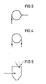
- the nozzle housing 1 is provided with an inlet bore 3 opening eccentrically into a swirl chamber 2 and with an inlet bore 6 arranged in an insert 4 coaxial to the nozzle axis 5, which has one or more inlet bores 7 at an angle from 45 ° to the nozzle axis opens into the swirl chamber.
- a rotationally symmetrical mixing chamber 8 adjoins the swirl chamber, in which the inlet chamber is located Mix holes 3 and 6 introduced partial streams so that the angular momentum of the eccentrically introduced partial stream is distributed over the entire liquid stream to be atomized.
- the outlet of the mixing chamber is led to the nozzle opening 9.
- a borehole leading radially or parallel to the nozzle axis with adjoining swirl-producing internals, such as swirl chamber plates or swirl-generating channels, can also be provided.
- the inlet bore 6 can be replaced by a bore parallel to the nozzle axis 5 (FIG. 5) or else a bore opening radially into the mixing chamber 8 (FIG. 3).
- the supply lines, not shown in the drawing, for the inlet bores 3 and 6 can be guided via fine control valves, so that the partial flows supplied to the bores and thus the spray angle of the entire liquid flow leaving the nozzle opening 9 can be adjusted without the nozzle having to be changed or internals having to be replaced . This also enables automatic control of the spray angle.
- a further embodiment of the nozzle according to the invention provides that two inlet bores are guided eccentrically and in the flow direction of the partial streams of the liquid to be atomized to be introduced into the swirl chamber and the downstream mixing chamber opposite to one another.
- swirl-generating internals can also be provided for the inlet bores.
- the nozzle according to the invention it is now possible to readjust the spray angle with a variable total volume flow through the nozzle, with fluctuations in the viscosity of the liquid to be atomized or with fluctuations in the solids content of the liquid. Conversely, with a constant volume flow, the spray angle can be changed over a wide range.
Landscapes
- Nozzles (AREA)
- Pressure-Spray And Ultrasonic-Wave- Spray Burners (AREA)
- Medicines That Contain Protein Lipid Enzymes And Other Medicines (AREA)
- Reciprocating Pumps (AREA)
Priority Applications (1)
| Application Number | Priority Date | Filing Date | Title |
|---|---|---|---|
| AT84103521T ATE38339T1 (de) | 1983-04-06 | 1984-03-30 | Hohlkegelzerstaeubungsduese. |
Applications Claiming Priority (2)
| Application Number | Priority Date | Filing Date | Title |
|---|---|---|---|
| DE19833312301 DE3312301A1 (de) | 1983-04-06 | 1983-04-06 | Hohlkegelzerstaeubungsduese |
| DE3312301 | 1983-04-06 |
Publications (3)
| Publication Number | Publication Date |
|---|---|
| EP0121877A2 true EP0121877A2 (fr) | 1984-10-17 |
| EP0121877A3 EP0121877A3 (en) | 1985-11-13 |
| EP0121877B1 EP0121877B1 (fr) | 1988-11-02 |
Family
ID=6195545
Family Applications (1)
| Application Number | Title | Priority Date | Filing Date |
|---|---|---|---|
| EP84103521A Expired EP0121877B1 (fr) | 1983-04-06 | 1984-03-30 | Buse de pulvérisation en forme d'un cône creux |
Country Status (5)
| Country | Link |
|---|---|
| EP (1) | EP0121877B1 (fr) |
| JP (1) | JPS59213462A (fr) |
| AT (1) | ATE38339T1 (fr) |
| DE (2) | DE3312301A1 (fr) |
| DK (1) | DK161947C (fr) |
Cited By (5)
| Publication number | Priority date | Publication date | Assignee | Title |
|---|---|---|---|---|
| US4977190A (en) * | 1988-06-10 | 1990-12-11 | Basf Aktiengesellschaft | Preparation of riboflavin, produced by a microbial method, in the form of spray-dried granules or microgranules |
| DE19608349A1 (de) * | 1996-03-05 | 1997-09-11 | Abb Research Ltd | Druckzerstäuberdüse |
| WO2006059065A1 (fr) * | 2004-12-01 | 2006-06-08 | Incro Limited | Agencement de buse comprenant une chambre de tourbillonnement |
| EP2629016A3 (fr) * | 2012-02-16 | 2017-05-17 | Delavan Inc. | Injection multipoint à angle variable |
| EP2962041B1 (fr) * | 2013-02-28 | 2020-05-13 | United Technologies Corporation | Chambre de combustion de turbine à gaz avec gicleur d'injecteur de carburant à turbulence variable |
Families Citing this family (3)
| Publication number | Priority date | Publication date | Assignee | Title |
|---|---|---|---|---|
| US5013877A (en) * | 1988-02-08 | 1991-05-07 | Raychem Corporation | Devices for electrical connection |
| DE9318544U1 (de) * | 1993-12-03 | 1994-01-27 | Rubenberger, Karl, 85435 Erding | Wirbelkammerzerstäuber |
| DE102021133674A1 (de) | 2021-12-17 | 2023-06-22 | Technische Universität Dresden | Düse mit einstellbarer Strahlgeometrie, Düsenanordnung und Verfahren zum Betrieb einer Düse |
Family Cites Families (8)
| Publication number | Priority date | Publication date | Assignee | Title |
|---|---|---|---|---|
| DE222120C (fr) * | ||||
| US2484577A (en) * | 1945-03-29 | 1949-10-11 | Monarch Mfg Works Inc | Double orifice solid cone spray nozzle |
| JPS525365B2 (fr) * | 1973-01-31 | 1977-02-12 | ||
| CH568781A5 (en) * | 1973-08-17 | 1975-11-14 | Kurylec Michael | Spray nozzle for removing dust from gases esp. smoke - whirl chamber in housing extends into dirt trap |
| US3908903A (en) * | 1974-02-11 | 1975-09-30 | Jr Samuel L Burns | Snow making apparatus and method |
| US3920187A (en) * | 1974-05-24 | 1975-11-18 | Porta Test Mfg | Spray head |
| DE2542240C3 (de) * | 1975-09-23 | 1981-07-30 | Lechler Gmbh & Co Kg, 7012 Fellbach | Hohlkegeldüse zum Zerstäuben von Flüssigkeit |
| DE2733102A1 (de) * | 1977-07-22 | 1979-02-01 | Bayer Ag | Verfahren und vorrichtung zum zerstaeuben von fluessigkeiten |
-
1983
- 1983-04-06 DE DE19833312301 patent/DE3312301A1/de not_active Withdrawn
-
1984
- 1984-03-30 AT AT84103521T patent/ATE38339T1/de not_active IP Right Cessation
- 1984-03-30 DE DE8484103521T patent/DE3474917D1/de not_active Expired
- 1984-03-30 EP EP84103521A patent/EP0121877B1/fr not_active Expired
- 1984-04-02 JP JP59063456A patent/JPS59213462A/ja active Granted
- 1984-04-05 DK DK179584A patent/DK161947C/da active
Cited By (10)
| Publication number | Priority date | Publication date | Assignee | Title |
|---|---|---|---|---|
| US4977190A (en) * | 1988-06-10 | 1990-12-11 | Basf Aktiengesellschaft | Preparation of riboflavin, produced by a microbial method, in the form of spray-dried granules or microgranules |
| DE19608349A1 (de) * | 1996-03-05 | 1997-09-11 | Abb Research Ltd | Druckzerstäuberdüse |
| EP0794383A3 (fr) * | 1996-03-05 | 1998-04-01 | Abb Research Ltd. | Buse de pulvérisation par pression |
| WO2006059065A1 (fr) * | 2004-12-01 | 2006-06-08 | Incro Limited | Agencement de buse comprenant une chambre de tourbillonnement |
| CN100544828C (zh) * | 2004-12-01 | 2009-09-30 | 英克罗有限公司 | 包含涡流室的喷嘴装置 |
| EP2629016A3 (fr) * | 2012-02-16 | 2017-05-17 | Delavan Inc. | Injection multipoint à angle variable |
| US9745936B2 (en) | 2012-02-16 | 2017-08-29 | Delavan Inc | Variable angle multi-point injection |
| US10480472B2 (en) | 2012-02-16 | 2019-11-19 | Delavan Inc. | Variable angle multi-point injection |
| EP2962041B1 (fr) * | 2013-02-28 | 2020-05-13 | United Technologies Corporation | Chambre de combustion de turbine à gaz avec gicleur d'injecteur de carburant à turbulence variable |
| US11326775B2 (en) | 2013-02-28 | 2022-05-10 | Raytheon Technologies Corporation | Variable swirl fuel nozzle |
Also Published As
| Publication number | Publication date |
|---|---|
| ATE38339T1 (de) | 1988-11-15 |
| DK179584A (da) | 1984-10-07 |
| JPH0448502B2 (fr) | 1992-08-06 |
| DE3312301A1 (de) | 1984-10-11 |
| EP0121877A3 (en) | 1985-11-13 |
| DK161947C (da) | 1992-02-03 |
| EP0121877B1 (fr) | 1988-11-02 |
| DK179584D0 (da) | 1984-04-05 |
| DE3474917D1 (en) | 1988-12-08 |
| DK161947B (da) | 1991-09-02 |
| JPS59213462A (ja) | 1984-12-03 |
Similar Documents
| Publication | Publication Date | Title |
|---|---|---|
| EP0698418B1 (fr) | Procédé et dispositif de dispersion et pulvérisation simultanées d'au moins deux fluides | |
| EP1243343B1 (fr) | Buse de vaporisation à deux fluides | |
| DE2252218C2 (de) | Vorrichtung zum Zerstäuben eines Fluids | |
| DE3116660C2 (de) | Mehrstoff-Zerstäuberdüse | |
| DE3889791T2 (de) | Zerstäuber. | |
| DE60009554T2 (de) | Vorrichtung zur zerstäubung einer flüssigkeit, mit dieser vorrichtung ausgerüstete anlage zum sprühtrocknen und konditionieren sowie verfahren zum konditionieren eines flüssigen produktes | |
| DE69115047T2 (de) | Zerstäubungsdüse. | |
| EP0268702B1 (fr) | Buse d'un pulvérisateur à air comprimé | |
| DE1923234A1 (de) | Verfahren und Spritzduese zum Erzeugen eines Faecherstrahles | |
| DE19752245C2 (de) | Zweistoffdüse und Niederdruck-Zerstäubungsvorrichtung mit mehreren benachbarten Zweistoffdüsen | |
| DE3609350C2 (fr) | ||
| EP0225624B1 (fr) | Tête de pulvérisation pour matière thermoplastique, en particulier pour un adhésif fusible | |
| DE3006558C2 (fr) | ||
| EP1062048A1 (fr) | Procede permettant de modifier le mouvement de rotation d'un fluide dans la chambre de rotation d'un gicleur et generateur de rotation pour gicleurs | |
| EP0121877B1 (fr) | Buse de pulvérisation en forme d'un cône creux | |
| EP1862214A2 (fr) | Procédé et dispositif destinés à relier des fibres dans la zone d'un tube de soufflage | |
| EP1514592B1 (fr) | Procédé et dispositif de mélange statique, en particulier pour l'encollage des fibres lignocellulosiques en utilisant un liant | |
| EP1186347A1 (fr) | Procédé et dispositif de pulvérisation de liquides | |
| DE3514931A1 (de) | Vorrichtung und verfahren zum einspeisen von schlamm | |
| DE3120260A1 (de) | Vorrichtung zum befeuchten von schuettguetern | |
| DE2148051A1 (de) | Einrichtung fuer den waerme- und/oder stoffaustausch zwischen substanzen und gasen | |
| DE19655254B4 (de) | Zweistoffdüse | |
| DE19526404A1 (de) | Verfahren und Vorrichtung zur Zerteilung eines Mediums | |
| DE3826690A1 (de) | Zerstaeubungsverfahren fuer fluessigkeiten | |
| DE202010005280U1 (de) | Zweistoffdüse |
Legal Events
| Date | Code | Title | Description |
|---|---|---|---|
| PUAI | Public reference made under article 153(3) epc to a published international application that has entered the european phase |
Free format text: ORIGINAL CODE: 0009012 |
|
| AK | Designated contracting states |
Designated state(s): AT BE CH DE FR GB IT LI NL SE |
|
| PUAL | Search report despatched |
Free format text: ORIGINAL CODE: 0009013 |
|
| AK | Designated contracting states |
Designated state(s): AT BE CH DE FR GB IT LI NL SE |
|
| 17P | Request for examination filed |
Effective date: 19851210 |
|
| 17Q | First examination report despatched |
Effective date: 19870205 |
|
| GRAA | (expected) grant |
Free format text: ORIGINAL CODE: 0009210 |
|
| AK | Designated contracting states |
Kind code of ref document: B1 Designated state(s): AT BE CH DE FR GB IT LI NL SE |
|
| REF | Corresponds to: |
Ref document number: 38339 Country of ref document: AT Date of ref document: 19881115 Kind code of ref document: T |
|
| ITF | It: translation for a ep patent filed | ||
| REF | Corresponds to: |
Ref document number: 3474917 Country of ref document: DE Date of ref document: 19881208 |
|
| GBT | Gb: translation of ep patent filed (gb section 77(6)(a)/1977) | ||
| ET | Fr: translation filed | ||
| PLBE | No opposition filed within time limit |
Free format text: ORIGINAL CODE: 0009261 |
|
| STAA | Information on the status of an ep patent application or granted ep patent |
Free format text: STATUS: NO OPPOSITION FILED WITHIN TIME LIMIT |
|
| 26N | No opposition filed | ||
| ITTA | It: last paid annual fee | ||
| EAL | Se: european patent in force in sweden |
Ref document number: 84103521.5 |
|
| PGFP | Annual fee paid to national office [announced via postgrant information from national office to epo] |
Ref country code: DE Payment date: 19991223 Year of fee payment: 17 |
|
| PGFP | Annual fee paid to national office [announced via postgrant information from national office to epo] |
Ref country code: AT Payment date: 20000216 Year of fee payment: 17 |
|
| PGFP | Annual fee paid to national office [announced via postgrant information from national office to epo] |
Ref country code: SE Payment date: 20000223 Year of fee payment: 17 Ref country code: FR Payment date: 20000223 Year of fee payment: 17 Ref country code: CH Payment date: 20000223 Year of fee payment: 17 |
|
| PGFP | Annual fee paid to national office [announced via postgrant information from national office to epo] |
Ref country code: NL Payment date: 20000224 Year of fee payment: 17 |
|
| PGFP | Annual fee paid to national office [announced via postgrant information from national office to epo] |
Ref country code: GB Payment date: 20000315 Year of fee payment: 17 |
|
| PGFP | Annual fee paid to national office [announced via postgrant information from national office to epo] |
Ref country code: BE Payment date: 20000327 Year of fee payment: 17 |
|
| PG25 | Lapsed in a contracting state [announced via postgrant information from national office to epo] |
Ref country code: DE Free format text: LAPSE BECAUSE OF THE APPLICANT RENOUNCES Effective date: 20010316 |
|
| PG25 | Lapsed in a contracting state [announced via postgrant information from national office to epo] |
Ref country code: GB Free format text: LAPSE BECAUSE OF NON-PAYMENT OF DUE FEES Effective date: 20010330 Ref country code: AT Free format text: LAPSE BECAUSE OF NON-PAYMENT OF DUE FEES Effective date: 20010330 |
|
| PG25 | Lapsed in a contracting state [announced via postgrant information from national office to epo] |
Ref country code: SE Free format text: LAPSE BECAUSE OF NON-PAYMENT OF DUE FEES Effective date: 20010331 Ref country code: LI Free format text: LAPSE BECAUSE OF NON-PAYMENT OF DUE FEES Effective date: 20010331 Ref country code: CH Free format text: LAPSE BECAUSE OF NON-PAYMENT OF DUE FEES Effective date: 20010331 Ref country code: BE Free format text: LAPSE BECAUSE OF NON-PAYMENT OF DUE FEES Effective date: 20010331 |
|
| BERE | Be: lapsed |
Owner name: BASF A.G. Effective date: 20010331 |
|
| PG25 | Lapsed in a contracting state [announced via postgrant information from national office to epo] |
Ref country code: NL Free format text: LAPSE BECAUSE OF NON-PAYMENT OF DUE FEES Effective date: 20011001 |
|
| EUG | Se: european patent has lapsed |
Ref document number: 84103521.5 |
|
| REG | Reference to a national code |
Ref country code: CH Ref legal event code: PL |
|
| GBPC | Gb: european patent ceased through non-payment of renewal fee |
Effective date: 20010330 |
|
| PG25 | Lapsed in a contracting state [announced via postgrant information from national office to epo] |
Ref country code: FR Free format text: LAPSE BECAUSE OF NON-PAYMENT OF DUE FEES Effective date: 20011130 |
|
| NLV4 | Nl: lapsed or anulled due to non-payment of the annual fee |
Effective date: 20011001 |
|
| REG | Reference to a national code |
Ref country code: FR Ref legal event code: ST |