EP0122181B1 - Machine pour la mise en état et/ou l'entretien des sols - Google Patents
Machine pour la mise en état et/ou l'entretien des sols Download PDFInfo
- Publication number
- EP0122181B1 EP0122181B1 EP84400528A EP84400528A EP0122181B1 EP 0122181 B1 EP0122181 B1 EP 0122181B1 EP 84400528 A EP84400528 A EP 84400528A EP 84400528 A EP84400528 A EP 84400528A EP 0122181 B1 EP0122181 B1 EP 0122181B1
- Authority
- EP
- European Patent Office
- Prior art keywords
- chassis
- motor
- axis
- transmission system
- shaft
- Prior art date
- Legal status (The legal status is an assumption and is not a legal conclusion. Google has not performed a legal analysis and makes no representation as to the accuracy of the status listed.)
- Expired
Links
- 238000012423 maintenance Methods 0.000 title claims abstract 3
- 230000003370 grooming effect Effects 0.000 title 1
- 230000005540 biological transmission Effects 0.000 claims abstract description 26
- 230000008878 coupling Effects 0.000 claims abstract description 10
- 238000010168 coupling process Methods 0.000 claims abstract description 10
- 238000005859 coupling reaction Methods 0.000 claims abstract description 10
- 241000282472 Canis lupus familiaris Species 0.000 claims description 9
- 238000006073 displacement reaction Methods 0.000 claims 1
- 238000004140 cleaning Methods 0.000 description 2
- 230000007717 exclusion Effects 0.000 description 2
- 238000010521 absorption reaction Methods 0.000 description 1
- 230000000903 blocking effect Effects 0.000 description 1
- 230000000295 complement effect Effects 0.000 description 1
- 238000005498 polishing Methods 0.000 description 1
- 230000001681 protective effect Effects 0.000 description 1
Images

Classifications
-
- A—HUMAN NECESSITIES
- A47—FURNITURE; DOMESTIC ARTICLES OR APPLIANCES; COFFEE MILLS; SPICE MILLS; SUCTION CLEANERS IN GENERAL
- A47L—DOMESTIC WASHING OR CLEANING; SUCTION CLEANERS IN GENERAL
- A47L11/00—Machines for cleaning floors, carpets, furniture, walls, or wall coverings
- A47L11/40—Parts or details of machines not provided for in groups A47L11/02 - A47L11/38, or not restricted to one of these groups, e.g. handles, arrangements of switches, skirts, buffers, levers
- A47L11/4002—Installations of electric equipment
- A47L11/4005—Arrangements of batteries or cells; Electric power supply arrangements
-
- A—HUMAN NECESSITIES
- A47—FURNITURE; DOMESTIC ARTICLES OR APPLIANCES; COFFEE MILLS; SPICE MILLS; SUCTION CLEANERS IN GENERAL
- A47L—DOMESTIC WASHING OR CLEANING; SUCTION CLEANERS IN GENERAL
- A47L11/00—Machines for cleaning floors, carpets, furniture, walls, or wall coverings
- A47L11/02—Floor surfacing or polishing machines
- A47L11/10—Floor surfacing or polishing machines motor-driven
- A47L11/14—Floor surfacing or polishing machines motor-driven with rotating tools
- A47L11/16—Floor surfacing or polishing machines motor-driven with rotating tools the tools being disc brushes
- A47L11/164—Parts or details of the brushing tools
-
- A—HUMAN NECESSITIES
- A47—FURNITURE; DOMESTIC ARTICLES OR APPLIANCES; COFFEE MILLS; SPICE MILLS; SUCTION CLEANERS IN GENERAL
- A47L—DOMESTIC WASHING OR CLEANING; SUCTION CLEANERS IN GENERAL
- A47L11/00—Machines for cleaning floors, carpets, furniture, walls, or wall coverings
- A47L11/40—Parts or details of machines not provided for in groups A47L11/02 - A47L11/38, or not restricted to one of these groups, e.g. handles, arrangements of switches, skirts, buffers, levers
- A47L11/4036—Parts or details of the surface treating tools
- A47L11/4038—Disk shaped surface treating tools
-
- A—HUMAN NECESSITIES
- A47—FURNITURE; DOMESTIC ARTICLES OR APPLIANCES; COFFEE MILLS; SPICE MILLS; SUCTION CLEANERS IN GENERAL
- A47L—DOMESTIC WASHING OR CLEANING; SUCTION CLEANERS IN GENERAL
- A47L11/00—Machines for cleaning floors, carpets, furniture, walls, or wall coverings
- A47L11/40—Parts or details of machines not provided for in groups A47L11/02 - A47L11/38, or not restricted to one of these groups, e.g. handles, arrangements of switches, skirts, buffers, levers
- A47L11/4052—Movement of the tools or the like perpendicular to the cleaning surface
- A47L11/4058—Movement of the tools or the like perpendicular to the cleaning surface for adjusting the height of the tool
-
- A—HUMAN NECESSITIES
- A47—FURNITURE; DOMESTIC ARTICLES OR APPLIANCES; COFFEE MILLS; SPICE MILLS; SUCTION CLEANERS IN GENERAL
- A47L—DOMESTIC WASHING OR CLEANING; SUCTION CLEANERS IN GENERAL
- A47L11/00—Machines for cleaning floors, carpets, furniture, walls, or wall coverings
- A47L11/40—Parts or details of machines not provided for in groups A47L11/02 - A47L11/38, or not restricted to one of these groups, e.g. handles, arrangements of switches, skirts, buffers, levers
- A47L11/4063—Driving means; Transmission means therefor
- A47L11/4069—Driving or transmission means for the cleaning tools
-
- A—HUMAN NECESSITIES
- A47—FURNITURE; DOMESTIC ARTICLES OR APPLIANCES; COFFEE MILLS; SPICE MILLS; SUCTION CLEANERS IN GENERAL
- A47L—DOMESTIC WASHING OR CLEANING; SUCTION CLEANERS IN GENERAL
- A47L11/00—Machines for cleaning floors, carpets, furniture, walls, or wall coverings
- A47L11/40—Parts or details of machines not provided for in groups A47L11/02 - A47L11/38, or not restricted to one of these groups, e.g. handles, arrangements of switches, skirts, buffers, levers
- A47L11/4075—Handles; levers
-
- F—MECHANICAL ENGINEERING; LIGHTING; HEATING; WEAPONS; BLASTING
- F16—ENGINEERING ELEMENTS AND UNITS; GENERAL MEASURES FOR PRODUCING AND MAINTAINING EFFECTIVE FUNCTIONING OF MACHINES OR INSTALLATIONS; THERMAL INSULATION IN GENERAL
- F16H—GEARING
- F16H9/00—Gearings for conveying rotary motion with variable gear ratio, or for reversing rotary motion, by endless flexible members
Definitions
- the present invention relates to a machine for preparing and / or maintaining floors.
- Machines of this type are already known comprising a chassis supporting a motor which drives in rotation at least one rotary tool, such as a brush, an abrasive disc, etc., at least one handle being provided for moving and / or controlling the movement of said machines, in particular from US-A-4 186 030. '
- these machines are designed to rotate said rotary tool more or less quickly and to exert on this tool, via their weight, a greater or lesser pressure.
- a machine for cleaning floors must be heavy, so that the tool exerts significant pressure on the ground, but the speed of rotation of said tool must be low, of the order of 200 revolutions / min, for example.
- a machine intended for polishing the floors must be light, so that the tool exerts only a low pressure on the floor and the speed of rotation of this tool must be high, for example of the order of 1 000 rpm.
- a machine intended for simple cleaning must be able to exert an average pressure on the ground by means of its rotary tool and the latter must rotate at an intermediate speed, for example of the order of 450 revolutions / min.
- this kind of machine has the disadvantage of being specialized in the work for which it is intended, so that the user must have at his disposal as many machines as he has different jobs to perform. It would be relatively easy to provide a gearbox or a variable speed drive to allow the speed of rotation of the tool of such a machine to be varied.
- the problem would not be solved however, since the pressure exerted by the machine on the ground, via the tool, would be constant and not adapted to each type of work.
- the machine for preparing and / or maintaining floors comprising a chassis supporting a motor which, by means of a transmission system, rotates at least one tool rotatable, such as a brush or a disc, about an axis orthogonal to said chassis, said chassis being mounted on two wheels rotating about an axis transverse to said chassis and disposed at one end thereof and said rotary tool being arranged at the end of the chassis opposite to said transverse axis of the wheels is remarkable in that said motor is capable of being removably mounted in several interchangeable positions distributed longitudinally along said chassis and in that said transmission system comprises, in each of said positions, coupling means for the axis of said motor, said transmission system being provided so that, the motor speed being constant, the speed of rotation
- said transmission system comprises a plurality of shafts of axis orthogonal to said chassis, that at least some of said shafts are accessible at said interchangeable positions and that quick coupling means are provided for coupling the motor shaft to said accessible shafts of the transmission system.
- These quick coupling means can be of the plug-in type, so that the coupling and cutting of the motor and the transmission system, at the various interchangeable positions, can be done by simple lowering and lifting of the motor.
- said motor is slidably mounted on a rail system linked to said chassis, and said rail system can be raised and lowered orthogonally relative to the chassis.
- the rail system is controlled by a lever articulated on the chassis.
- the machine When, as is usual, the machine includes a handle for moving and / or controlling the movements of said machine, it is advantageous for this handle to act as such a lever.
- said handle is rotatably mounted with respect to the chassis, and the lifting and lowering of said rail system are controlled by the rotation of said handle.
- the motor drives only the part of the transmission system necessary for the rotation of the tool.
- the transmission system includes erasable dogs; and said dogs are erased by the shaft of said motor, when the latter is placed in the corresponding position, so that certain parts of the transmission system, not directly useful for driving the tool, can be uncoupled of the engine, when it occupies some of its positions.
- the machine according to the invention shown in Figure 1, comprises a chassis 1 on which is mounted an electric motor 2 whose axis 3-3 is orthogonal to said chassis.
- Two wheels 4 are arranged on either side of the chassis 1, at one end of it and define an axis 5-5.
- a handle 6 equipped with a handle 7 and operating members 8 is articulated to the chassis 1, around an axis 9-9, on the side thereof where the wheels 4 are arranged.
- a fork 10 is articulated to the chassis 1 around an axis 11-11 parallel to the axis 9-9 and is integral with a ring 12 which can slide on the handle 6 and be fixed in position thereon by means of 'a member (not shown), such as a pressure screw.
- the machine At the end of the chassis 1, opposite the wheels 4 and the handle 6, the machine comprises a tool 13 rotating around a vertical axis 14-14, such as a brush or an abrasive disc, possibly partially or totally enveloped by a protective cover.
- a tool 13 rotating around a vertical axis 14-14, such as a brush or an abrasive disc, possibly partially or totally enveloped by a protective cover.
- the motor 2 is integral with a flange 15, trapped in sliding (see in particular FIG. 4) of two rails 16 parallel to each other and extending longitudinally on the chassis 1.
- the motor 2 can occupy several positions along the chassis 1, namely the position shown in solid lines in FIG. 1 for which the axis 3-3 is close to the axis 5-5 of the wheels 4 and positions which move further and further away from the handle 6 for which the axis 3-3 of the motor 2 takes positions 3'-3 'and 3 "-3".
- the rails 16 are integral with studs 17 passing through the chassis 1 and able to slide vertically in bearings 18. They are controlled by rods 19 which can slide longitudinally relative to guides 20, by means of rods 21.
- the rods 19 are provided with pins 22 engaged with cams 23, wedged on the axis 9-9 of the handle 6.
- the motor 2 is uncoupled from the tool 13 and it can be slid along said rails 16 (its flange 15 remaining trapped therein) so that its axis can come to take any one of positions 3-3, 3'-3 'or 3 "-3".
- the handlebars 6 are then lowered (arrow F2 in FIG. 2) and the rails 16 come to rest on the chassis 1, while the motor 2 is again coupled to the 'tool 13.
- the pressure screw of the ring 12 is then tightened so that the handle 6 is fixed in angular position by the fork 10.
- the transmission system between the motor 2 and the tool 13 comprises four shafts journalled relative to the chassis 1, namely the shaft 25 with an axis 14-14 to which the tool 13 is fixed (not shown in FIG. 5), the shaft 26 of axis 3-3, the shaft 27 of axis 3'-3 'and the shaft 28 of axis 3 "-3".
- each of the shafts 25 and 28 is keyed only one pulley, respectively bearing the reference 29 or 30.
- two pulleys namely a keyed pulley 31 or 32 respectively and a clutch pulley 33 or 34 respectively.
- the dogs 35 and 36 are loaded respectively by springs 37 and 38, towards their dog clutch position.
- Belts 41, 42 and 43 respectively connect the pulley 29 of the shaft 25 and the keyed pulley 31 of the shaft 26, the clutch pulley 33 of shaft 26 and keyed pulley 32 of shaft 27 and pulley 30 of shaft 28 and clutch pulley 34 of shaft 27.
- the end of the shaft 44 of the motor 2 is shaped as a screwdriver blade 45, while the end, accessible through the chassis 1, of the shafts 26, 27 and 28 is shaped as a complementary slot 46.
- the motor shaft 2 is coupled by direct fitting of the end 45 into said slots 46 of the shafts 26, 27 and 28.
- the motor shaft 2 drives the shaft 25 of the tool 13 thanks to the entire chain 28-30- 43-34-27-32-42-33-26-31-41 and 29.
- the dog clutch 36 is in its position uncoupling (since the end 45 pushes the rod 40) so that the pulley 34 is not driven. It is therefore the same for the belt 43 and the pulley 30.
- the pulley 32 keyed on the axis 27 is driven, so that the tool 13 is then rotated by the chain part 27- 32-42-33-26-31-41-29 and 25.
Landscapes
- Engineering & Computer Science (AREA)
- General Engineering & Computer Science (AREA)
- Mechanical Engineering (AREA)
- Finish Polishing, Edge Sharpening, And Grinding By Specific Grinding Devices (AREA)
- Manufacture Of Motors, Generators (AREA)
- Catching Or Destruction (AREA)
- Disintegrating Or Milling (AREA)
- Micro-Organisms Or Cultivation Processes Thereof (AREA)
- Other Air-Conditioning Systems (AREA)
Description
- La présente invention concerne une machine pour la mise en état et/ou l'entretien des sols.
- On connaît déjà des machines de ce type comportant un châssis supportant un moteur qui entraîne en rotation au moins un outil rotatif, tel qu'une brosse, un disque abrasif, etc., au moins un mancheron étant prévu pour déplacer et/ou contrôler le déplacement desdites machines notamment du US-A-4 186 030. '
- Dans des machines connues de ce type, il est fréquent de ne prévoir qu'un seul essieu transversal au châssis disposé à une extrémité de celui-ci et pourvu d'une roue à chacune de ses extrémités, ledit moteur étant monté au moins sensiblement à l'aplomb dudit essieu, tandis que l'outil rotatif est assujetti à tourner autour d'un axe fixe orthogonal au châssis et est agencé à l'extrémité de celui-ci opposée audit essieu.
- Suivant l'usage auquel elles sont destinées, ces machines sont prévues pour faire tourner ledit outil rotatif plus ou moins vite et pour exercer sur cet outil, par l'intermédiaire de leur poids, une pression plus ou moins grande. Par exemple, une machine destinée au décrassage des sols doit être lourde, pour que l'outil exerce une pression importante sur le sol, mais la vitesse de rotation dudit outil doit être faible, de l'ordre de 200 tours/mn, par exemple. En revanche, une machine destinée au lustrage des sols doit être légère, pour que l'outil n'exerce qu'une faible pression sur le sol et la vitesse de rotation de cet outil doit être grande, par exemple de l'ordre de 1 000 tours/mn. Enfin, une machine destinée à un simple nettoyage doit pouvoir exercer une pression moyenne sur le sol par l'intermédiaire de son outil rotatif et celui-ci doit tourner à une vitesse intermédiaire, par exemple de l'ordre de 450 tours/mn.
- Ainsi, ce genre de machine présente l'inconvénient d'être spécialisée dans le travail auquel elle est destinée, de sorte que l'utilisateur doit avoir à sa disposition autant de machines qu'il a de travaux différents à effectuer. Il serait relativement facile de prévoir une boîte de vitesses ou un variateur de vitesses pour permettre de faire varier la vitesse de rotation de l'outil d'une telle machine. Cependant, outre les inconvénients propres à ce genre de mécanismes (obligation d'utiliser de l'huile pour les boîtes de vitesses et donc risque de taches sur les sols à nettoyer, perte de puissance pour les variateurs), le problème ne serait pas résolu pour autant, puisque la pression exercée par la machine sur le sol, par l'intermédiaire de l'outil, serait constante et non pas adaptée à chaque type de travaux.
- La présente invention a pour objet de remédier à ces inconvénients. Elle concerne une machine du type mentionné ci-dessus pouvant être instantanément adaptée, en ce qui concerne la vitesse de rotation et la pression exercée par son outil rotatif, au type de travail que l'on désire effectuer. A cette fin, selon l'invention, la machine pour la mise en état et/ou l'entretien des sols comportant un châssis supportant un moteur qui, par l'intermédiaire d'un système de transmission, entraîne en rotation au moins un outil rotatif, tel qu'une brosse ou un disque, autour d'un axe orthogonal audit châssis, ledit châssis étant monté sur deux roues tournant autour d'un axe transversal audit châssis et disposé à une extrémité de celui-ci et ledit outil rotatif étant agencé à l'extrémité du châssis opposée audit axe transversal des roues est remarquable en ce que ledit moteur est susceptible d'être monté de façon amovible en plusieurs positions interchangeables réparties longitudinalement le long dudit châssis et en ce que ledit système de transmission comporte, en chacune desdites positions, des moyens de couplage pour l'axe dudit moteur, ledit système de transmission étant prévu pour que, la vitesse du moteur étant constante, la vitesse de rotation de l'outil soit d'autant plus faible que le moteur est en une position plus proche de l'extrémité du châssis opposée audit axe des roues.
- Ainsi, grâce d'une part, audit système de transmission et d'autre part, au choix de la position du moteur, on fait varier simultanément la vitesse de rotation de l'outil et la pression exercée par celui-ci sur le sol, ces variations étant coordonnées pour que cette vitesse de rotation soit d'autant plus grande que la pression exercée est plus faible et vice versa.
- Dans le cas où, de façon usuelle, l'axe de l'arbre du moteur est orthogonal au châssis, il est avantageux que ledit système de transmission comporte une pluralité d'arbres d'axe orthogonal audit châssis, qu'au moins certains desdits arbres soient accessibles auxdites positions interchangeables et que des moyens de couplage rapide soient prévus pour coupler l'arbre du moteur auxdits arbres accessibles du système de transmission. Ces moyens de couplage rapide peuvent être du type à emboîtement en bout, de sorte que le couplage et le découpage du moteur et du système de transmission, aux différentes positions interchangeables, peuvent se faire par simples abaissements et levages du moteur.
- Dans un mode de réalisation avantageux à cet effet, ledit moteur est monté coulissant sur un système de rails lié audit châssis, et ledit système de rails peut être levé et abaissé orthogonalement par rapport au châssis.
- Par exemple, la commande du système de rails est réalisée par un levier articulé sur le châssis.
- Lorsque, comme cela est usuel, la machine comporte un mancheron pour déplacer et/ou contrôler les déplacements de ladite machine, il est avantageux que ce mancheron fasse office d'un tel levier. Dans ce cas, ledit mancheron est monté rotatif par rapport au châssis, et le levage et l'abaissement dudit système de rails sont commandés par la rotation dudit mancheron.
- Par ailleurs, pour éviter une absorption d'énergie trop importante par le système de transmission et éviter que certains arbres de celui-ci ne tournent trop vite pour certaines positions du moteur (ce qui engendrerait des bruits et une usure importants), il est avantageux que, pour chacune de ses positions, le moteur n'entraîne que la partie du système de transmission nécessaire à la rotation de l'outil. Pour ce faire, le système de transmission comporte des crabots effaçables ; et lesdits crabots sont effacés par l'arbre dudit moteur, lorsque celui-ci est mis en place dans la position correspondante, de sorte que certaines parties du système de transmission, non directement utiles pour l'entraînement de l'outil, peuvent être désaccouplées du moteur, lorsque celui-ci occupe certaines de ses positions.
- Les figures du dessin annexé feront bien comprendre comment l'invention peut être réalisée.
- La figure 1 est une vue en perspective schématique d'une machine conforme à l'invention.
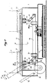
- La figure 2 est une coupe agrandie, schématique et partielle, passant par l'axe longitudinal de la machine de la figure 1, montrant le système de rails pour le moteur, à l'exclusion du système de transmission qui a été supprimé à des fins de clarté.
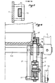
- La figure 3 est une coupe selon la ligne III-III de la figure 2.
- La figure 4. qui correspond à la ligne de coupe IV-IV de la figure 2, illustre le montage du moteur dans le système de rails et la commande de celui-ci.
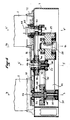
- La figure 5 est une coupe agrandie, schématique et partielle, passant par l'axe longitudinal de la machine de la figure 1, montrant le système de transmission, à l'exclusion du système de rails qui a été supprimé à des fins de clarté.
- Sur ces figures des références identiques désignent des éléments semblables.
- La machine selon l'invention, montrée par la figure 1, comporte un châssis 1 sur lequel est monté un moteur électrique 2 dont l'axe 3-3 est orthogonal audit châssis. Deux roues 4 sont disposées de part et d'autre du châssis 1, à une extrémité de celui-ci et définissent un axe 5-5.
- Par ailleurs, un mancheron 6 équipé d'une poignée 7 et d'organes de manoeuvre 8 est articulé au châssis 1, autour d'un axe 9-9, du côté de celui-ci où sont disposées les roues 4.
- Une fourche 10 est articulée au châssis 1 autour d'un axe 11-11 parallèle à l'axe 9-9 et est solidaire d'une bague 12 pouvant coulisser sur le mancheron 6 et être fixée en position sur celui-ci au moyen d'un organe (non représenté), tel qu'une vis de pression.
- A l'extrémité du châssis 1, opposée aux roues 4 et au mancheron 6, la machine comporte un outil 13 rotatif autour d'un axe vertical 14-14, tel qu'une brosse ou un disque abrasif, éventuellement partiellement ou totalement enveloppé par un capot de protection.
- A sa partie inférieure, le moteur 2 est solidaire d'une bride 15, prisonnière en coulissement (voir notamment la figure 4) de deux rails 16 parallèles l'un à l'autre et s'étendant longitudinalement sur le châssis 1.
- Grâce à ce système de rails 16, comme on le verra après, le moteur 2 peut occuper plusieurs positions le long du châssis 1, à savoir la position représentée en trait plein sur la figure 1 pour laquelle l'axe 3-3 est proche de l'axe 5-5 des roues 4 et des positions qui s'éloignent de plus en plus du mancheron 6 pour lesquelles l'axe 3-3 du moteur 2 vient prendre des positions 3'-3' et 3"-3".
- A cet effet, les rails 16 sont solidaires de goujons 17 traversant le châssis 1 et pouvant coulisser verticalement dans des paliers 18. Ils sont commandés par des tringles 19 pouvant coulisser longitudinalement par rapport à des guides 20, par l'intermédiaire de biellettes 21. Sur les tringles 19 sont prévus des ergots 22 en prise avec des cames 23, calées sur l'axe 9-9 du mancheron 6.
- Ainsi, lorsque la vis de pression bloquant la position de la bague 12 sur le mancheron 6 est desserrée, celui-ci peut être relevé (flèche F1 de la figure 2), ladite bague coulissant sur ledit mancheron. Ce mouvement de relevage dudit mancheron 6 entraîne, grâce à la coopération des organes 23-22-19-20-21-17 et 18, le levage des rails 16 au-dessus du châssis 1.
- Dans cette position levée des rails 16, comme on le verra ci-après, le moteur 2 est désaccouplé de l'outil 13 et il peut être coulissé le long desdits rails 16 (sa bride 15 restant prisonnière de ceux- ci) pour que son axe puisse venir prendre l'une quelconque des positions 3-3, 3'-3' ou 3"-3".
- Lorsque l'axe du moteur 2 est dans la position choisie, on abaisse alors le mancheron 6 (flèche F2 sur la figure 2) et les rails 16 reviennent en appui sur le châssis 1, tandis que le moteur 2 est de nouveau accouplé à l'outil 13. On serre alors la vis de pression de la bague 12 de sorte que le mancheron 6 est fixé en position angulaire par la fourche 10.
- Comme le montre la figure 5, le système de transmission entre le moteur 2 et l'outil 13 comporte quatre arbres tourillonnés par rapport au châssis 1, à savoir l'arbre 25 d'axe 14-14 auquel est fixé l'outil 13 (non représenté sur la figure 5), l'arbre 26 d'axe 3-3, l'arbre 27 d'axe 3'-3' et l'arbre 28 d'axe 3"-3".
- Sur chacun des arbres 25 et 28 n'est clavetée qu'une seule poulie, portant respectivement la référence 29 ou 30. En revanche, sur chacun des arbres 26 et 27 sont prévues deux poulies, à savoir une poulie clavetée 31 ou 32 respectivement et une poulie crabotée 33 ou 34 respectivement. Les crabots 35 et 36 sont chargés respectivement par des ressorts 37 et 38, vers leur position de crabotage.
- Cependant, ces crabots peuvent être commandés au décrabotage par l'action de tiges 39 et 40, lorsque celles-ci sont repoussées à l'encontre de l'action desdits ressorts 37 et 38.
- Des courroies 41, 42 et 43, par exemple de type cranté, relient respectivement la poulie 29 de l'arbre 25 et la poulie clavetée 31 de l'arbre 26, la poulie crabotée 33 de l'arbre 26 et la poulie clavetée 32 de l'arbre 27 et la poulie 30 de l'arbre 28 et la poulie crabotée 34 de l'arbre 27.
- De plus. l'extrémité de l'arbre 44 du moteur 2 est conformée en lame de tournevis 45, alors que l'extrémité, accessible à travers le châssis 1, des arbres 26, 27 et 28 est conformée en fente complémentaire 46.
- Par suite, l'accouplement de l'arbre du moteur 2 se fait par emboîtement direct de l'extrémité 45 dans lesdites fentes 46 des arbres 26, 27 et 28.
- Lorsque le moteur 2 est dans la position pour ' laquelle son axe est en position 3"-3", l'arbre de moteur 2 entraîne l'arbre 25 de l'outil 13 grâce à l'intégralité de la chaîne 28-30-43-34-27-32-42-33-26-31-41 et 29. En revanche, lorsque l'axe de l'arbre du moteur 2 est en position 3'-3', le crabot 36 est dans sa position de désaccouplement (puisque l'extrémité 45 repousse la tige 40) de sorte que la poulie 34 n'est pas entraînée. Il en est donc de même de la courroie 43 et de la poulie 30. En revanche, la poulie 32 clavetée sur l'axe 27 est entraînée, de sorte que l'outil 13 est alors mis en rotation par la partie de chaîne 27-32-42-33-26-31-41-29 et 25. Enfin, lorsque l'axe de l'arbre du moteur 2 est en position 3-3, le crabot 35 est dans sa position de désaccouplement (puisque l'extrémité 45 repousse la tige 39) de sorte que la poulie 33 n'est pas entraînée. Il en est donc de même de la courroie 42, des poulies 32 et 34, de l'axe 27, de la courroie 43 et de la poulie 30. En revanche, la poulie clavetée 31 est entraînée, de sorte que l'outil 13 est mis en rotation par la partie de chaîne 26-31-41-29 et 25.
- On comprendra aisément qu'avec le système de transmission montré par la figure 5, il est possible de faire en sorte que, la vitesse du moteur 2 étant constante la vitesse de rotation de l'outil 13 puisse être d'autant plus faible que le moteur est en une position plus proche de l'extrémité du châssis opposée à l'axe 5-5 des roues 4.
- Il suffit pour cela de choisir de façon appropriée le diamètre des poulies 29 à 34.
- Afin d'éviter des vibrations et les bruits correspondant, ainsi que pour éviter un désaccouplement inopportun du moteur 2 par rapport au châssis 1, il peut être avantageux de prévoir des moyens élastiques (non représentés), prenant par exemple appui sur les tringles 19, pour exercer une action tendant à appliquer ledit moteur sur ledit châssis.
Claims (6)
Priority Applications (1)
| Application Number | Priority Date | Filing Date | Title |
|---|---|---|---|
| AT84400528T ATE21022T1 (de) | 1983-03-17 | 1984-03-14 | Maschine fuer die instandsetzung und/oder fuer die fussbodenpflege. |
Applications Claiming Priority (2)
| Application Number | Priority Date | Filing Date | Title |
|---|---|---|---|
| FR8304408A FR2542836B1 (fr) | 1983-03-17 | 1983-03-17 | Machine pour la mise en etat et/ou l'entretien des sols |
| FR8304408 | 1983-03-17 |
Publications (2)
| Publication Number | Publication Date |
|---|---|
| EP0122181A1 EP0122181A1 (fr) | 1984-10-17 |
| EP0122181B1 true EP0122181B1 (fr) | 1986-07-30 |
Family
ID=9286969
Family Applications (1)
| Application Number | Title | Priority Date | Filing Date |
|---|---|---|---|
| EP84400528A Expired EP0122181B1 (fr) | 1983-03-17 | 1984-03-14 | Machine pour la mise en état et/ou l'entretien des sols |
Country Status (4)
| Country | Link |
|---|---|
| EP (1) | EP0122181B1 (fr) |
| AT (1) | ATE21022T1 (fr) |
| DE (1) | DE3460377D1 (fr) |
| FR (1) | FR2542836B1 (fr) |
Families Citing this family (2)
| Publication number | Priority date | Publication date | Assignee | Title |
|---|---|---|---|---|
| EP1498063A1 (fr) * | 2003-07-18 | 2005-01-19 | WALSER & CO. AG | Méthode et appareil pour le nettoyage de surfaces, en particulier de sols |
| SE542372C2 (en) * | 2018-04-04 | 2020-04-21 | Husqvarna Ab | A floor surfacing machine with a tool holder disc comprising a biasing member |
Family Cites Families (4)
| Publication number | Priority date | Publication date | Assignee | Title |
|---|---|---|---|---|
| DE583651C (de) * | 1930-03-18 | 1933-09-07 | Hermann Futterknecht | Flaechenbearbeitungsmaschine, insbesondere fuer Fussboeden u. dgl. |
| US3407422A (en) * | 1966-07-27 | 1968-10-29 | Clarke Floor Machine Division | Brush attachment for floor machine |
| US4186030A (en) * | 1976-11-04 | 1980-01-29 | Armstrong John L | Carpet cleaning |
| FR2393562A1 (fr) * | 1977-06-06 | 1979-01-05 | Plasse Freres Sa | Monobrosse combinee |
-
1983
- 1983-03-17 FR FR8304408A patent/FR2542836B1/fr not_active Expired
-
1984
- 1984-03-14 EP EP84400528A patent/EP0122181B1/fr not_active Expired
- 1984-03-14 DE DE8484400528T patent/DE3460377D1/de not_active Expired
- 1984-03-14 AT AT84400528T patent/ATE21022T1/de not_active IP Right Cessation
Also Published As
| Publication number | Publication date |
|---|---|
| EP0122181A1 (fr) | 1984-10-17 |
| FR2542836A1 (fr) | 1984-09-21 |
| FR2542836B1 (fr) | 1985-06-21 |
| DE3460377D1 (en) | 1986-09-04 |
| ATE21022T1 (de) | 1986-08-15 |
Similar Documents
| Publication | Publication Date | Title |
|---|---|---|
| EP1178154B1 (fr) | Meuleuse de profils de rails | |
| EP0143820B1 (fr) | Transmission a engrenage comportant deux vis sans fin | |
| EP0124462A1 (fr) | Machine agricole à dispositif de transmission de mouvement perfectionné | |
| EP0073725B1 (fr) | Machine pour la mise en état et/ou l'entretien des sols | |
| FR2546454A1 (fr) | Vehicule de travail autopropulse | |
| EP0122181A1 (fr) | Machine pour la mise en état et/ou l'entretien des sols | |
| FR2563247A1 (fr) | Ratiere d'armures rotative | |
| FR2533985A1 (fr) | Outil portatif a transmission mecanique souple | |
| EP0869858B1 (fr) | Unite d'usinage a tete rotative | |
| FR2467037A1 (fr) | Appareil de dressage et d'alesage | |
| FR2774953A1 (fr) | Transmission de vitesse pour tondeuse a gazon et tondeuse a gazon equipee d'une telle transmission | |
| FR2545185A1 (fr) | Support a ressort possedant une force portante constante | |
| WO2019145611A1 (fr) | Machine tronçonneuse de rails d'une voie de chemin de fer | |
| EP0655188B1 (fr) | Machine de fenaison | |
| FR2823061A1 (fr) | Machine de recolte avec un dispositif d'entrainement perfectionne | |
| CH361393A (fr) | Appareil à écorcer les billes ou grumes de bois | |
| EP0077859B1 (fr) | Accouplement à friction, notamment pour machines de récolte | |
| FR2637250A1 (fr) | Variateur de vitesse pour cycle | |
| CH664516A5 (en) | Dental mandrel for boring or cutting - has central hole of chuck tilted obliquely by slide | |
| FR2483295A1 (fr) | Dispositif de rectification de forme speciale utilise dans une machine-outil a commande numerique | |
| EP0554629A1 (fr) | Machine de rodage par expansion | |
| EP0467816B1 (fr) | Appareil pour l'élimination des fibres et des duvets textiles | |
| FR2554063A1 (fr) | Engin mobile destine notamment a l'agriculture | |
| FR2793431A3 (fr) | Machine a chanfreiner | |
| BE561925A (fr) |
Legal Events
| Date | Code | Title | Description |
|---|---|---|---|
| PUAI | Public reference made under article 153(3) epc to a published international application that has entered the european phase |
Free format text: ORIGINAL CODE: 0009012 |
|
| AK | Designated contracting states |
Designated state(s): AT BE CH DE GB IT LI LU NL SE |
|
| 17P | Request for examination filed |
Effective date: 19841011 |
|
| GRAA | (expected) grant |
Free format text: ORIGINAL CODE: 0009210 |
|
| AK | Designated contracting states |
Kind code of ref document: B1 Designated state(s): AT BE CH DE GB IT LI LU NL SE |
|
| REF | Corresponds to: |
Ref document number: 21022 Country of ref document: AT Date of ref document: 19860815 Kind code of ref document: T |
|
| REF | Corresponds to: |
Ref document number: 3460377 Country of ref document: DE Date of ref document: 19860904 |
|
| ITF | It: translation for a ep patent filed | ||
| PLBE | No opposition filed within time limit |
Free format text: ORIGINAL CODE: 0009261 |
|
| STAA | Information on the status of an ep patent application or granted ep patent |
Free format text: STATUS: NO OPPOSITION FILED WITHIN TIME LIMIT |
|
| 26N | No opposition filed | ||
| ITTA | It: last paid annual fee | ||
| PGFP | Annual fee paid to national office [announced via postgrant information from national office to epo] |
Ref country code: SE Payment date: 19940316 Year of fee payment: 11 |
|
| PGFP | Annual fee paid to national office [announced via postgrant information from national office to epo] |
Ref country code: NL Payment date: 19940331 Year of fee payment: 11 Ref country code: LU Payment date: 19940331 Year of fee payment: 11 Ref country code: AT Payment date: 19940331 Year of fee payment: 11 |
|
| PGFP | Annual fee paid to national office [announced via postgrant information from national office to epo] |
Ref country code: DE Payment date: 19940425 Year of fee payment: 11 |
|
| EPTA | Lu: last paid annual fee | ||
| EAL | Se: european patent in force in sweden |
Ref document number: 84400528.0 |
|
| PGFP | Annual fee paid to national office [announced via postgrant information from national office to epo] |
Ref country code: GB Payment date: 19950308 Year of fee payment: 12 |
|
| PG25 | Lapsed in a contracting state [announced via postgrant information from national office to epo] |
Ref country code: LU Free format text: LAPSE BECAUSE OF NON-PAYMENT OF DUE FEES Effective date: 19950314 Ref country code: AT Effective date: 19950314 |
|
| PG25 | Lapsed in a contracting state [announced via postgrant information from national office to epo] |
Ref country code: SE Effective date: 19950315 |
|
| PGFP | Annual fee paid to national office [announced via postgrant information from national office to epo] |
Ref country code: CH Payment date: 19950327 Year of fee payment: 12 |
|
| PG25 | Lapsed in a contracting state [announced via postgrant information from national office to epo] |
Ref country code: NL Effective date: 19951001 |
|
| PGFP | Annual fee paid to national office [announced via postgrant information from national office to epo] |
Ref country code: BE Payment date: 19951004 Year of fee payment: 12 |
|
| NLV4 | Nl: lapsed or anulled due to non-payment of the annual fee |
Effective date: 19951001 |
|
| PG25 | Lapsed in a contracting state [announced via postgrant information from national office to epo] |
Ref country code: DE Effective date: 19951201 |
|
| EUG | Se: european patent has lapsed |
Ref document number: 84400528.0 |
|
| PG25 | Lapsed in a contracting state [announced via postgrant information from national office to epo] |
Ref country code: GB Effective date: 19960314 |
|
| PG25 | Lapsed in a contracting state [announced via postgrant information from national office to epo] |
Ref country code: LI Effective date: 19960331 Ref country code: CH Effective date: 19960331 Ref country code: BE Effective date: 19960331 |
|
| BERE | Be: lapsed |
Owner name: PLAZANET MAURICE PIERRE Effective date: 19960331 |
|
| GBPC | Gb: european patent ceased through non-payment of renewal fee |
Effective date: 19960314 |
|
| REG | Reference to a national code |
Ref country code: CH Ref legal event code: PL |