EP0122221A1 - Dispositif de chauffage - Google Patents
Dispositif de chauffage Download PDFInfo
- Publication number
- EP0122221A1 EP0122221A1 EP84810050A EP84810050A EP0122221A1 EP 0122221 A1 EP0122221 A1 EP 0122221A1 EP 84810050 A EP84810050 A EP 84810050A EP 84810050 A EP84810050 A EP 84810050A EP 0122221 A1 EP0122221 A1 EP 0122221A1
- Authority
- EP
- European Patent Office
- Prior art keywords
- combustion chamber
- arrangement according
- heating arrangement
- afterburner
- wall
- Prior art date
- Legal status (The legal status is an assumption and is not a legal conclusion. Google has not performed a legal analysis and makes no representation as to the accuracy of the status listed.)
- Withdrawn
Links
- 238000010438 heat treatment Methods 0.000 title claims description 18
- 238000002485 combustion reaction Methods 0.000 claims description 28
- 239000007789 gas Substances 0.000 claims description 20
- 239000003546 flue gas Substances 0.000 claims description 9
- UGFAIRIUMAVXCW-UHFFFAOYSA-N Carbon monoxide Chemical compound [O+]#[C-] UGFAIRIUMAVXCW-UHFFFAOYSA-N 0.000 claims description 7
- 238000005192 partition Methods 0.000 claims 3
- 230000000149 penetrating effect Effects 0.000 claims 1
- 239000011449 brick Substances 0.000 abstract 1
- 239000011521 glass Substances 0.000 abstract 1
- 239000004575 stone Substances 0.000 abstract 1
- 238000001816 cooling Methods 0.000 description 3
- 239000007787 solid Substances 0.000 description 3
- 239000000779 smoke Substances 0.000 description 2
- QVGXLLKOCUKJST-UHFFFAOYSA-N atomic oxygen Chemical compound [O] QVGXLLKOCUKJST-UHFFFAOYSA-N 0.000 description 1
- 239000003054 catalyst Substances 0.000 description 1
- 238000004140 cleaning Methods 0.000 description 1
- 230000001419 dependent effect Effects 0.000 description 1
- 239000000428 dust Substances 0.000 description 1
- 230000007613 environmental effect Effects 0.000 description 1
- 238000010304 firing Methods 0.000 description 1
- 239000000446 fuel Substances 0.000 description 1
- 239000001301 oxygen Substances 0.000 description 1
- 229910052760 oxygen Inorganic materials 0.000 description 1
- 239000002245 particle Substances 0.000 description 1
- 230000035515 penetration Effects 0.000 description 1
- XLYOFNOQVPJJNP-UHFFFAOYSA-N water Substances O XLYOFNOQVPJJNP-UHFFFAOYSA-N 0.000 description 1
- 239000002023 wood Substances 0.000 description 1
Images

Classifications
-
- F—MECHANICAL ENGINEERING; LIGHTING; HEATING; WEAPONS; BLASTING
- F23—COMBUSTION APPARATUS; COMBUSTION PROCESSES
- F23B—METHODS OR APPARATUS FOR COMBUSTION USING ONLY SOLID FUEL
- F23B5/00—Combustion apparatus with arrangements for burning uncombusted material from primary combustion
- F23B5/04—Combustion apparatus with arrangements for burning uncombusted material from primary combustion in separate combustion chamber; on separate grate
-
- F—MECHANICAL ENGINEERING; LIGHTING; HEATING; WEAPONS; BLASTING
- F23—COMBUSTION APPARATUS; COMBUSTION PROCESSES
- F23L—SUPPLYING AIR OR NON-COMBUSTIBLE LIQUIDS OR GASES TO COMBUSTION APPARATUS IN GENERAL ; VALVES OR DAMPERS SPECIALLY ADAPTED FOR CONTROLLING AIR SUPPLY OR DRAUGHT IN COMBUSTION APPARATUS; INDUCING DRAUGHT IN COMBUSTION APPARATUS; TOPS FOR CHIMNEYS OR VENTILATING SHAFTS; TERMINALS FOR FLUES
- F23L3/00—Arrangements of valves or dampers before the fire
-
- F—MECHANICAL ENGINEERING; LIGHTING; HEATING; WEAPONS; BLASTING
- F23—COMBUSTION APPARATUS; COMBUSTION PROCESSES
- F23M—CASINGS, LININGS, WALLS OR DOORS SPECIALLY ADAPTED FOR COMBUSTION CHAMBERS, e.g. FIREBRIDGES; DEVICES FOR DEFLECTING AIR, FLAMES OR COMBUSTION PRODUCTS IN COMBUSTION CHAMBERS; SAFETY ARRANGEMENTS SPECIALLY ADAPTED FOR COMBUSTION APPARATUS; DETAILS OF COMBUSTION CHAMBERS, NOT OTHERWISE PROVIDED FOR
- F23M9/00—Baffles or deflectors for air or combustion products; Flame shields
Definitions
- the present invention relates to a heating device with a cylindrical combustion chamber, the main axis of which is arranged horizontally, according to the preamble of independent patent claim 1.
- the heating device 10 consists of a combustion chamber 21 with a comprehensive boiler 20 and a boiler jacket 19 forming the outer wall.
- the combustion chamber 21 is through on the loading side a door 11, which is fastened to the boiler casing 19 by means of supports 11a and hinges 11b.
- this door 11 there is a small square door 12 for charging during the burning of fuels.
- In the small door 12 there is an air flap 13 for secondary air, and a further air flap 14 for primary air is located below this small door 12 in the large door 11.
- a temperature-dependent tension regulator 15 is mounted on the boiler casing 19, for example on the thermal behavior of one Bimetal coil is based.
- Two traction elements 16 connect the tension controller 15 with the two air flaps 13, 14.
- the tension elements 16 are set such that the lower air damper 14 closes the water temperature in the boiler and the upper air damper 13 at about 85 ° C at about 70 0 C. This ensures that good gas combustion is obtained due to the supply of oxygen above the embers.
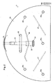
- An afterburner wall 26 which closes off the upper part of the combustion chamber 21 is inserted in the combustion chamber 21 at a distance from the rear combustion chamber wall 25.
- baffle plates 27 arranged symmetrically to the central plane through the main axis of the combustion chamber. These baffles 27 are inclined at an angle in the range of 30 ° to the horizontal and are spaced at their lower, adjacent ends by about 20 the diameter of the combustion chamber, and at the upper outer ends there is still a free passage of about 10% to to the wall of the combustion chamber 21.
- the height of the afterburner wall 25 is approximately 10 greater than the radius of the combustion chamber 21, and the distance of the afterburner wall 25 from the rear combustion chamber wall 25 is approximately 15% of the diameter.
- a baffle plate 28 in the form of an M is located above these baffles 27, at a point a short distance below the exhaust pipe 23.
- the exhaust gases are accelerated and swirled by this arrangement of guide plates 27 and deflection plate 28.
- the exhaust gases in the afterburner chamber can be ignited by means of openings 29a, 29b and 29c, which were produced as round bores with a diameter of 15 mm. It has been shown that even cold gases with a temperature of less than 450 ° C are burned and thereby heated to a temperature in the range of 800 ° C. This means that the flue gas cooling can be put into operation very early and the requirement that only colorless flue gas may be released from the chimney after 3 minutes.
- a stop plate 34 is braced in the exhaust pipe 23 by means of a pipe sleeve 33 and a threaded bolt 33a.
- a stepped bracket 32 is attached to the tubular sleeve. This support bracket 32 serves to hold the baffle plate 28. The free end of the support bracket 32 is inserted through a slot opening 35 in the afterburner wall 26 and on the front side of the afterburner wall 26 by a guide pin 31 against the end face of the baffle plates 28 as a counterhold pressed.
- the baffles 27 are attached to the afterburner wall 26. This is provided with a handle 30 for easier handling when inserting and removing.
- first opening 29a At the point of penetration of the main axis through the after burner wall 26 arranged.
- Two further openings 29b are located at the same height as the first-mentioned opening 29a, but in the edge region and at a distance of approximately 10% from the edge.
- Two other openings 29c are also located in the edge region at the same distance from the edge as the aforementioned two openings 29b, but at least approximately at the level of the lower part of the exhaust pipe 23.
- the deflection plate 28 is formed in one piece. Of course, this can also consist of two parts which are attached to the bracket 32 with screws.
- the exhaust gas flow in the afterburner chamber can be adapted to the chimney draft using slotted holes in the two baffle plates.
Landscapes
- Engineering & Computer Science (AREA)
- Chemical & Material Sciences (AREA)
- Combustion & Propulsion (AREA)
- Mechanical Engineering (AREA)
- General Engineering & Computer Science (AREA)
- Physics & Mathematics (AREA)
- Thermal Sciences (AREA)
- Incineration Of Waste (AREA)
Applications Claiming Priority (2)
| Application Number | Priority Date | Filing Date | Title |
|---|---|---|---|
| CH61383 | 1983-02-03 | ||
| CH613/83 | 1983-02-03 |
Publications (1)
| Publication Number | Publication Date |
|---|---|
| EP0122221A1 true EP0122221A1 (fr) | 1984-10-17 |
Family
ID=4191069
Family Applications (1)
| Application Number | Title | Priority Date | Filing Date |
|---|---|---|---|
| EP84810050A Withdrawn EP0122221A1 (fr) | 1983-02-03 | 1984-01-27 | Dispositif de chauffage |
Country Status (1)
| Country | Link |
|---|---|
| EP (1) | EP0122221A1 (fr) |
Citations (5)
| Publication number | Priority date | Publication date | Assignee | Title |
|---|---|---|---|---|
| AT29988B (de) * | 1902-04-30 | 1907-09-25 | Richard Schulz | Einrichtung zur Rauchverbrennung bei Wasserrohrkesselfeuerungen mit hinter dem Feuerherde liegendem Feuerzugteil aus feuerfestem Stoffe, in welchem die Feuergase erst nach Durchstreichen des einen Rohrbündels eintreten. |
| GB191024609A (en) * | 1910-10-24 | 1911-10-24 | Henry Askew | Improvements in and relating to the Furnaces of Steam Boilers and other Furnaces. |
| CH204489A (de) * | 1938-03-21 | 1939-05-15 | Muehlethaler Waldvogel Ewald | Vorrichtung zum Anzeigen von Störungen an Feuerungen. |
| CH599508A5 (fr) * | 1976-12-23 | 1978-05-31 | Sander Spaenex Gmbh & Co Kg | |
| DD148813A1 (de) * | 1980-01-25 | 1981-06-10 | Udo Becher | Anordnung zur regelung der sekundaerluftzufuhr fuer feststoffrostfeuerungen |
-
1984
- 1984-01-27 EP EP84810050A patent/EP0122221A1/fr not_active Withdrawn
Patent Citations (5)
| Publication number | Priority date | Publication date | Assignee | Title |
|---|---|---|---|---|
| AT29988B (de) * | 1902-04-30 | 1907-09-25 | Richard Schulz | Einrichtung zur Rauchverbrennung bei Wasserrohrkesselfeuerungen mit hinter dem Feuerherde liegendem Feuerzugteil aus feuerfestem Stoffe, in welchem die Feuergase erst nach Durchstreichen des einen Rohrbündels eintreten. |
| GB191024609A (en) * | 1910-10-24 | 1911-10-24 | Henry Askew | Improvements in and relating to the Furnaces of Steam Boilers and other Furnaces. |
| CH204489A (de) * | 1938-03-21 | 1939-05-15 | Muehlethaler Waldvogel Ewald | Vorrichtung zum Anzeigen von Störungen an Feuerungen. |
| CH599508A5 (fr) * | 1976-12-23 | 1978-05-31 | Sander Spaenex Gmbh & Co Kg | |
| DD148813A1 (de) * | 1980-01-25 | 1981-06-10 | Udo Becher | Anordnung zur regelung der sekundaerluftzufuhr fuer feststoffrostfeuerungen |
Similar Documents
| Publication | Publication Date | Title |
|---|---|---|
| DE60108711T2 (de) | Vormischbrenner mit niedrigem NOx-Ausstoss und Verfahren dafür | |
| DE2820933C2 (de) | Feuerung für feste Brennstoffe | |
| DE69412999T2 (de) | Raumheizer für feste brennstoffe | |
| DE4406446A1 (de) | Heizeinrichtung für gasförmige Brennstoffe | |
| AT397554B (de) | Vorrichtung zum verbrennen fester brennstoffe, insbesondere holz | |
| EP0122221A1 (fr) | Dispositif de chauffage | |
| DE2812962C2 (de) | Heizofen für Holz | |
| DE4403615B4 (de) | Verteilungsvorrichtung für Sekundärluft in einer Heizeinrichtung | |
| DE69001197T2 (de) | Kesselglied fuer niedertemperatur-heizkessel. | |
| DE3503554C2 (fr) | ||
| EP0058991A2 (fr) | Four pour la combustion de combustibles solides, en particulier du bois | |
| DE2737902C2 (fr) | ||
| DE3229063C2 (de) | Vorrichtung zum Anzünden von Festbrennstoffen in einem für feste und flüssige oder gasförmige Brennstoffe ausgelegten Heizkessel | |
| DE4009316A1 (de) | Heizvorrichtung fuer feste brennstoffe | |
| DD238260A5 (de) | Atmosphaerischer warmwasserkessel mit unten angeordnetem verbrennungsraum, insbesondere fuer gasfeuerung | |
| DE1778291C3 (de) | Heizvorrichtung für flüssige, gasförmige und/oder feste Brennstoffe | |
| AT412306B (de) | Ofen zur befeuerung von festem brennstoff | |
| CH632079A5 (en) | Heating device | |
| DE3140498A1 (de) | Heizofen mit vielstoffbrennraum und sekundaerluftzufuhr | |
| DE3302957C2 (fr) | ||
| DE69800253T2 (de) | Ausbaufähige Heizung | |
| CH680159A5 (fr) | ||
| DE3429268A1 (de) | Verbrennungseinrichtung | |
| DE3404237A1 (de) | Verbrennungsofen | |
| DE1194112B (de) | Heizkessel fuer Warmwasserheizungsanlagen |
Legal Events
| Date | Code | Title | Description |
|---|---|---|---|
| PUAI | Public reference made under article 153(3) epc to a published international application that has entered the european phase |
Free format text: ORIGINAL CODE: 0009012 |
|
| AK | Designated contracting states |
Designated state(s): AT BE CH DE FR GB IT LI LU NL SE |
|
| STAA | Information on the status of an ep patent application or granted ep patent |
Free format text: STATUS: THE APPLICATION IS DEEMED TO BE WITHDRAWN |
|
| 18D | Application deemed to be withdrawn |
Effective date: 19850618 |
|
| RIN1 | Information on inventor provided before grant (corrected) |
Inventor name: LINIGER, ARMIN |