EP0122616A2 - Porte basculante avec dispositif de protection - Google Patents
Porte basculante avec dispositif de protection Download PDFInfo
- Publication number
- EP0122616A2 EP0122616A2 EP84104168A EP84104168A EP0122616A2 EP 0122616 A2 EP0122616 A2 EP 0122616A2 EP 84104168 A EP84104168 A EP 84104168A EP 84104168 A EP84104168 A EP 84104168A EP 0122616 A2 EP0122616 A2 EP 0122616A2
- Authority
- EP
- European Patent Office
- Prior art keywords
- side part
- vertical frame
- frame side
- housing
- protective
- Prior art date
- Legal status (The legal status is an assumption and is not a legal conclusion. Google has not performed a legal analysis and makes no representation as to the accuracy of the status listed.)
- Withdrawn
Links
Images

Classifications
-
- E—FIXED CONSTRUCTIONS
- E05—LOCKS; KEYS; WINDOW OR DOOR FITTINGS; SAFES
- E05D—HINGES OR SUSPENSION DEVICES FOR DOORS, WINDOWS OR WINGS
- E05D15/00—Suspension arrangements for wings
- E05D15/40—Suspension arrangements for wings supported on arms movable in vertical planes
- E05D15/42—Suspension arrangements for wings supported on arms movable in vertical planes with pivoted arms and horizontally-sliding guides
- E05D15/425—Suspension arrangements for wings supported on arms movable in vertical planes with pivoted arms and horizontally-sliding guides specially adapted for overhead wings
-
- E—FIXED CONSTRUCTIONS
- E05—LOCKS; KEYS; WINDOW OR DOOR FITTINGS; SAFES
- E05D—HINGES OR SUSPENSION DEVICES FOR DOORS, WINDOWS OR WINGS
- E05D13/00—Accessories for sliding or lifting wings, e.g. pulleys, safety catches
- E05D13/10—Counterbalance devices
- E05D13/12—Counterbalance devices with springs
- E05D13/1207—Counterbalance devices with springs with tension springs
- E05D13/1223—Spring safety devices
-
- E—FIXED CONSTRUCTIONS
- E05—LOCKS; KEYS; WINDOW OR DOOR FITTINGS; SAFES
- E05D—HINGES OR SUSPENSION DEVICES FOR DOORS, WINDOWS OR WINGS
- E05D13/00—Accessories for sliding or lifting wings, e.g. pulleys, safety catches
- E05D13/10—Counterbalance devices
- E05D13/12—Counterbalance devices with springs
- E05D13/1207—Counterbalance devices with springs with tension springs
- E05D13/1215—Counterbalance devices with springs with tension springs specially adapted for overhead wings
-
- E—FIXED CONSTRUCTIONS
- E05—LOCKS; KEYS; WINDOW OR DOOR FITTINGS; SAFES
- E05Y—INDEXING SCHEME ASSOCIATED WITH SUBCLASSES E05D AND E05F, RELATING TO CONSTRUCTION ELEMENTS, ELECTRIC CONTROL, POWER SUPPLY, POWER SIGNAL OR TRANSMISSION, USER INTERFACES, MOUNTING OR COUPLING, DETAILS, ACCESSORIES, AUXILIARY OPERATIONS NOT OTHERWISE PROVIDED FOR, APPLICATION THEREOF
- E05Y2900/00—Application of doors, windows, wings or fittings thereof
- E05Y2900/10—Application of doors, windows, wings or fittings thereof for buildings or parts thereof
- E05Y2900/106—Application of doors, windows, wings or fittings thereof for buildings or parts thereof for garages
Definitions
- the invention relates to a tiltable gate, in particular for garages and the like, with a fixed frame which has at least one substantially vertical frame side part, with at least one gate wing tiltable within the frame about a horizontal axis and with at least one handlebar in the form of a with the gate wing in the same direction of rotation pivotable double-armed lever with unequal-length lever arms arranged on both sides of a pivot bearing assigned to the vertical frame side part, the longer of which is articulated on the gate wing and on the shorter one of which a spring arrangement with its opposite end engages the vertical frame side part, the pivot bearing , the shorter lever arm on its range of motion and the spring arrangement are arranged in a detachably attached to the vertical frame side part, reaching into the interior of the garage.
- Such a tilt gate is known from DE-PS 913 269.
- the spring arrangement is in this case designed as a tension spring which runs essentially vertically in the direction of the floor from the shorter lever arm, the opposite of which; lower end is attached to the bottom part of a one-piece and self-contained housing.
- the pivot bearing is designed as an integral part of the housing. For this purpose, edge regions surrounding an opening in each of the two opposite housing walls are flanged to form slide bearings for an axis connecting the shorter and the longer lever arm of the handlebar.
- the housing is not only designed as a protective housing, but also as a force-transmitting element, the pivot bearing and the spring arrangement being attached indirectly to the vertical frame side part via the housing.
- DE-OS 30 26 612 and DE-OS 30 26 660 it is known, by means of a spring covering, which also surrounds the pivot bearing and the shorter lever arm when the gate leaf is closed, to counter the dangers posed by a broken spring.
- this is not a generic housing that is fixed to the goal frame and that covers all of the moving parts so that it is always safe to touch, but rather a U-shaped envelope that is open towards the goal frame and that together with the shorter lever arm and the spring arrangement when Opening the gate away from the goal frame and thus providing no protection against the risk of damage and injury, which is much more frequent than in the case of spring breakage, for objects placed in the range of motion of the handlebars or for people, mainly children, who operate the gate, especially when it is operated by a motor. reach into this range of motion or into the spring arrangement.
- the protective housing in the form of a vertical frame side part training open protective hood.
- the opening formed in the protective housing for the passage of the handlebar is preferably covered by a protective cover. Injuries to the edge of the opening, which acts as a dangerous shear edge when the handlebars are moved, are therefore excluded.
- the protective screen is advantageously designed as a rotary screen that is detachably attached to the handlebar.
- the rotary screen can also be constructed in several parts.
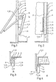
- a tiltable garage door includes a fixed frame 1 which is anchored in the masonry 2 of a garage and a gate leaf 3 which can be tilted within the frame 1 about a horizontal axis (not shown here).
- the frame 1 consists of two vertically extending frame side parts which are horizontally separated by a frame base. and a frame upper part are connected.
- a handlebar 5, a spring arrangement 6 in the form of a tension spring and a protective housing in the form of a protective hood 7 with a protective cover 8 are associated with each vertical frame side part and can be pivoted about a pivot bearing 4.
- Each handlebar 5 can be pivoted together with the gate leaf 3 in the same direction of rotation.
- the frame 1 is shown here only by one of the vertically running frame side parts, which is also provided with the reference number 1. The following description is limited to this frame side part and the associated components 4 to 8.
- the pivot bearing 4 is arranged in a frame projection 9 on an inside 11 of the vertical frame side part 1 facing the garage interior 10.
- the handlebar 5 consists of a double-armed lever with a longer lever arm 12 and a shorter lever arm 13, both of which are connected to one another by an offset 14.
- the offset 14 here represents the axle of the handlebar 5 which is mounted within the pivot bearing 4. Instead of this handlebar axle which is integrally formed with the handlebar, it is of course also possible to use a separate axle and to fix the lever arms 12 and 13 on both axle ends.
- the handlebar 5 is articulated with its longer lever arm 12 via a linkage 15 on the inside of the gate leaf 3 in its lower corner region and is supported with its shorter lever arm 13 on the vertical frame side part 1 via the spring arrangement 6.
- the shorter lever arm 13 has a bore 16 in the upper end of the spring arrangement b is suspended.
- the fastening of the opposite lower end 24 of this spring arrangement 6 takes place via a projection 17 on the inside 11 of the vertical frame side part 1.
- the protective hood 7 has two parallel side walls 18 and 19, each of which abuts one vertical edge of the frame inner side 11 of the vertical frame side part 1. These side walls 18 and 19 are mounted on both sides of the pivot bearing 4, the shorter lever arm 13 and the spring arrangement 6. They are cut (see Figure 1) so that they encapsulate the range of motion of the shorter lever arm 13 and the spring arrangement 6, the frame projection 9, the pivot bearing 4 and the corresponding part of the offset 14 are also included.
- the side walls 18 and 19 essentially have the shape of a trapezoid cut in half along its axis of symmetry, the larger trapezoidal parallel side being arranged at the top and merging approximately into the trapezoidal leg following the pivoting circle of the shorter lever arm 13 .
- Both side walls 18 and 19 are connected along their upper and lower parallel trapezoidal sides and their trapezoidal legs by an end wall 20, so that the hood opening faces the inside of the frame 11.
- an opening is provided in the lowermost part of the end wall 20 for receiving a downward projection of the projection 17.
- the upper part of the protective hood 7 is fastened to the frame projection 9 by means of screws 21. The attachment can of course also be done directly on the frame.
- the side wall 18 of the protective hood 7 has a cutout 22 which extends from the hood opening in the direction of the end wall 20 and which enables the protective hood 7 to be attached to the inside of the frame 11 and in its end region to allow the offset 14 to pass through.
- the protective cover 8 is provided to cover the cutout 22.
- it is circular and essentially covers the end region of the cutout.
- the remaining part of the cutout is closed from the inside of the protective hood 7 by the frame projection 9.
- the protective screen 8 has a central opening for the appropriate passage of the bent portion 14.
- it is designed as a rotary diaphragm which is fastened to the handlebar 5 or the bent portion 14 with a clamp seat and which rotates together with the handlebar 5.
- This protective cover 8 is pushed onto the longer lever arm 12 of the handlebar 5 before the gate wing 3 is attached to the side wall 18 of the protective cover 7 for this purpose
- the protective cover 7 can also be made, for example , of metal, in two parts and fastened to the handlebar 5 by means of screws.
- Figure 3 shows the attachment of the frame 1 in the reveal of the masonry 2.
- Figure 4 shows the arrangement of the frame 1 behind the reveal of the masonry.
- Figure 5 shows a third embodiment of the invention.
- the bent portion 14 extends obliquely to the lever arms 12 and 13 and is fastened to an axle 23 which is mounted in the frame projection 9 and protrudes from the protective hood 7.
- This attachment takes place in the passage area of the axle 23 through the side wall 18 of the protective hood 7 - the protective cover 8 is also embodied here as a rotary cover detachably attached to the handlebar. It covers the part of the axis 23 protruding from the protective hood 7 and the cutout 22 and thus also the part of the offset 14 which also protrudes.
- openings in the side wall 18 which are necessary for the passage of the bend 14 through the side wall 18 during the pivoting movement of the handlebar 5 are also covered by a corresponding design of the rotary screen.
- the protective panel 8 can also be detachably attached to the protective hood 7, the slot required for the lever arm 12 to pass through the protective hood 7 is preferably covered by a sliding panel attached to the lever arm 12 and a bellows etc.
- the spring arrangement consists of two or more tension springs or springs of another type.
- the handlebar mechanism including the spring arrangement can be arranged on one side or on both sides of the frame.
- the protective cover can also be a one-piece component of the protective covering, but this design is not limited to a multi-part or detachably attached protective covering.
- the protective housing consists only of the side wall 18 facing the interior of the garage and the end wall 20 and, if appropriate, a part of the side wall 19 attached to the end wall 20. This simpler design is particularly interesting when the distance to the garage wall is small.
- the protective housing can be appropriately reinforced to protect against spring breakage.
Landscapes
- Engineering & Computer Science (AREA)
- Mechanical Engineering (AREA)
- Gates (AREA)
- Steering Devices For Bicycles And Motorcycles (AREA)
Applications Claiming Priority (2)
| Application Number | Priority Date | Filing Date | Title |
|---|---|---|---|
| DE3313739 | 1983-04-15 | ||
| DE19833313739 DE3313739C2 (de) | 1983-04-15 | 1983-04-15 | Kippbares Tor mit Schutzvorrichtung |
Publications (2)
| Publication Number | Publication Date |
|---|---|
| EP0122616A2 true EP0122616A2 (fr) | 1984-10-24 |
| EP0122616A3 EP0122616A3 (fr) | 1985-10-16 |
Family
ID=6196525
Family Applications (1)
| Application Number | Title | Priority Date | Filing Date |
|---|---|---|---|
| EP84104168A Withdrawn EP0122616A3 (fr) | 1983-04-15 | 1984-04-13 | Porte basculante avec dispositif de protection |
Country Status (2)
| Country | Link |
|---|---|
| EP (1) | EP0122616A3 (fr) |
| DE (1) | DE3313739C2 (fr) |
Cited By (1)
| Publication number | Priority date | Publication date | Assignee | Title |
|---|---|---|---|---|
| EP0982465A3 (fr) * | 1998-08-28 | 2002-01-09 | Hörmann Kg Amshausen | Dispositif de protection pour porte basculante |
Family Cites Families (5)
| Publication number | Priority date | Publication date | Assignee | Title |
|---|---|---|---|---|
| DE913269C (de) * | 1951-10-17 | 1954-06-10 | Glenn Berry | In einer oberen Einschubfuehrung haengendes hochschwenkbares Tor, insbesondere fuer Garagen, mit seitlichen Lenkern |
| DE3026612C2 (de) * | 1980-07-14 | 1984-01-19 | Erich 9442 Berneck St. Gallen Döring | Garagenschwingtor mit Federschutz |
| DE3112926C2 (de) * | 1980-07-14 | 1984-04-26 | Erich 9442 Berneck St. Gallen Döring | Garagenschwingtor mit Federschutz |
| DE3026660C2 (de) * | 1980-07-14 | 1982-05-13 | Erich 9442 Berneck St. Gallen Döring | Garagenschwingtor |
| FR2508088A1 (fr) * | 1981-06-18 | 1982-12-24 | Remonato Andre | Systeme d'equilibrage de porte basculante |
-
1983
- 1983-04-15 DE DE19833313739 patent/DE3313739C2/de not_active Expired - Fee Related
-
1984
- 1984-04-13 EP EP84104168A patent/EP0122616A3/fr not_active Withdrawn
Cited By (2)
| Publication number | Priority date | Publication date | Assignee | Title |
|---|---|---|---|---|
| EP0982465A3 (fr) * | 1998-08-28 | 2002-01-09 | Hörmann Kg Amshausen | Dispositif de protection pour porte basculante |
| EP1325998A3 (fr) * | 1998-08-28 | 2003-10-15 | Hörmann Kg Amshausen | Dispositif de protection pour porte basculante |
Also Published As
| Publication number | Publication date |
|---|---|
| DE3313739A1 (de) | 1984-10-18 |
| DE3313739C2 (de) | 1994-05-11 |
| EP0122616A3 (fr) | 1985-10-16 |
Similar Documents
| Publication | Publication Date | Title |
|---|---|---|
| DE102007017916B3 (de) | Scharnieranordnung | |
| DE3320824C2 (fr) | ||
| DE3152291C2 (fr) | ||
| EP0628691B2 (fr) | Ferrure pour battant de fenêtres, portes etc. | |
| DE60223944T2 (de) | Gelenkkonstruktion | |
| EP0122616A2 (fr) | Porte basculante avec dispositif de protection | |
| CH714076A1 (de) | Maschinenverkleidung. | |
| DE1027085B (de) | Fahrzeugeinstieg | |
| DE3925117A1 (de) | Zentrifuge | |
| AT216926B (de) | Beschlag für Dreh-Kipp-Flügel von Fenstern, Türen od. dgl. | |
| DE3026660A1 (de) | Garagenschwingtor mit torfluegel-fang-vorrichtung | |
| CH302008A (de) | Tür- und Fensterflügelanhebevorrichtung. | |
| DE102019128057A1 (de) | Gebäudelüftungsvorrichtung zum Einbau in eine Wanddurchbruchsöffnung | |
| DE1962906C3 (de) | Beschlag fur Dreh-Kipp- oder Dreh-Klappfenster | |
| DE379932C (de) | Vorrichtung zum Verschieben und Feststellen von Schiebefenstern mittels einer mit dem Fenster verbundenen Stange | |
| DE4419779B4 (de) | Türsicherungsvorrichtung | |
| DE1939290A1 (de) | Sicherungsvorrichtung fuer Schwenk-Kippfenster | |
| DE60030808T2 (de) | Klappe für Strohofen | |
| DE3616679A1 (de) | Belueftungsriegel | |
| DE2934815A1 (de) | Vorrichtung zum auf- und zuhalten eines tuerfluegels | |
| DE2140833A1 (de) | Kippscharnier fuer die frontscheibe einer theke | |
| DE2858112C2 (fr) | ||
| DE4304371A1 (de) | Antrieb zum Öffnen und/oder Schließen einer Pendeltür | |
| AT221388B (de) | Ausstellvorrichtung für Dreh-Kipp-Fenster, -Türen od. dgl. | |
| DE1892518U (de) | Ausstellschere fuer dreh-kipp-fenster. |
Legal Events
| Date | Code | Title | Description |
|---|---|---|---|
| PUAI | Public reference made under article 153(3) epc to a published international application that has entered the european phase |
Free format text: ORIGINAL CODE: 0009012 |
|
| AK | Designated contracting states |
Designated state(s): AT BE CH DE FR GB IT LI LU NL SE |
|
| PUAL | Search report despatched |
Free format text: ORIGINAL CODE: 0009013 |
|
| AK | Designated contracting states |
Designated state(s): AT BE CH DE FR GB IT LI LU NL SE |
|
| STAA | Information on the status of an ep patent application or granted ep patent |
Free format text: STATUS: THE APPLICATION IS DEEMED TO BE WITHDRAWN |
|
| 18D | Application deemed to be withdrawn |
Effective date: 19860618 |
|
| RIN1 | Information on inventor provided before grant (corrected) |
Inventor name: KURZ, HUBERT, PROF. DR.-ING. |