EP0122718A2 - Appareillage et méthode pour la commande automatique du vol d'un aéronef - Google Patents
Appareillage et méthode pour la commande automatique du vol d'un aéronef Download PDFInfo
- Publication number
- EP0122718A2 EP0122718A2 EP84301723A EP84301723A EP0122718A2 EP 0122718 A2 EP0122718 A2 EP 0122718A2 EP 84301723 A EP84301723 A EP 84301723A EP 84301723 A EP84301723 A EP 84301723A EP 0122718 A2 EP0122718 A2 EP 0122718A2
- Authority
- EP
- European Patent Office
- Prior art keywords
- signal
- altitude
- value
- capture
- aircraft
- Prior art date
- Legal status (The legal status is an assumption and is not a legal conclusion. Google has not performed a legal analysis and makes no representation as to the accuracy of the status listed.)
- Granted
Links
Images

Classifications
-
- G—PHYSICS
- G05—CONTROLLING; REGULATING
- G05D—SYSTEMS FOR CONTROLLING OR REGULATING NON-ELECTRIC VARIABLES
- G05D1/00—Control of position, course, altitude or attitude of land, water, air or space vehicles, e.g. using automatic pilots
- G05D1/04—Control of altitude or depth
- G05D1/06—Rate of change of altitude or depth
- G05D1/0607—Rate of change of altitude or depth specially adapted for aircraft
- G05D1/0615—Rate of change of altitude or depth specially adapted for aircraft to counteract a perturbation, e.g. gust of wind
- G05D1/0623—Rate of change of altitude or depth specially adapted for aircraft to counteract a perturbation, e.g. gust of wind by acting on the pitch
Definitions
- the present invention relates generally to automatic flight control systems and methods of flight control for aircraft and more specifically to prediction of the commencement of altitude acquisition and the control of the aircraft flight path during actual altitude capture in such a way as to maintain accelerations normal to the flight path at or below a predetermined value.
- most automatic flight control systems include an altitude capture subsystem, whereby a desired altitude may be preselected by the human pilot while the aircraft is at an entirely different altitude and upon achieving predetermined conditions, automatically capturing that altitude.
- the aircraft's air data computer continuously supplies the altitude capture submode parameters, altitude error, the difference between the preselected altitude and the actual altitude, hereinafter referred to as h , and the actual vertical speed or altitude rate, hereinafter referred to as h
- the capture of the preselected altitude commences.
- altitude capture commences when the term (h - Kh a ) reaches a null value and by maintaining (h - Kh ) near zero,-an asymptotic flight path to the pre-selected altitude results.
- the value of the constant K defines the time constant or duration of the capture manoeuvre and is generally chosen to provide a timely altitude capture while keeping the aircraft's acceleration normal to the flight path, the g effect, at an acceptable comfortable value.
- K For small values of K, unacceptable acceleration levels may be experienced when the aircraft is at relatively hight altitude rates at capture initiation. Conversely, for large values of K, an unacceptable long time-to-altitude capture period occurs with lower altitude rates at capture initiation.
- a fixed path in space relative to the atmosphere is commanded.
- the time rate of change of the commanded path represents the acceleration of the aircraft relative to the flight path.
- the commanded path results in an asymptotic approach to the preselected altitude and, hence, a varying normal acceleration.
- the commanded path is circular, and hence represents a constant acceleration throughout the altitude capture.
- a significant shortcoming of either scheme is that the resultant normal acceleration on the aircraft is not necessarily that which was commanded at the inception of, or during, the capture manoeuvre. For example, if the altitude rate of the aircraft is increasing just prior to commencement of the capture manoeuvre due to an autopilot command to capture a commanded speed slower than the actual speed, the actual flight path of the aircraft will initially differ significantly from the commanded flight path. The resultant correction toward the commanded flight path can cause normal accelerations of an unacceptable level.
- the present invention overcomes all of the aforementioned shortcomings. It provides a prediction or anticipation of an incipient altitude capture such that the actual flight path of the aircraft corresponds with the commanded flight path at the commencement of the capture manoeuvre. Hence, unacceptable normal accelerations due to aircraft path correction is eliminated. Furthermore, the present invention alters the determination of the value of K such that the commanded capture results in either an asymptotic capture, a circular capture, or a combination of both depending upon existing conditions.
- the present invention is defined in the appended claims and provides means for the anticipation or prediction of an imminent commencement of an automatic capture of a preselected altitude to assure correlation of the actual flight path of an aircraft with the commanded flight path of the capture manoeuvre.
- the commanded flight path of the capture manoeuvre is adapted as a function of the altitude rate of the aircraft to either an asymptotic flight path, a circular flight path, or a combination of either in order to provide timely altitude captures with minimum accelerations normal to the flight path.
- the present invention is useful in any automatic pilot system or in any performance management system (PMS) which is fully coupled to an automatic pilot system and provides apparatus for automatically and adaptively transitioning the aircraft from a climb or descent mode to an altitude capture mode.
- PMS performance management system
- PMS performance management system
- the climb or descent is usually performed at some desired or commanded airspeed, Mach number or vertical speed, this commanded parameter being controlled by controlling the aircraft pitch attitude.
- the climb or descent is made at a commanded constant Mach number which speed is maintained by controlling aircraft pitch attitude.
- the invention is, of course, applicable to other than this mode.
- the Mach-on-pitch speed control will command a pitch-up manoeuvre to reduce speed, resulting in a greater rate of climb. If the altitude capture mode is initiated before the new speed is obtained, a pitch transient will occur as the command to the autopilot goes for a pitch-up to reduce speed to a pitch-down to capture the altitude, resulting in an excessive acceleration normal to the flight path, i.e. excessive g's which may be uncomfortable or alarming to the crew as well as the passengers. In accordance with the present invention, this transient is substantially reduced or eliminated by predetermining how much time remains before the altitude capture mode is initiated and reducing the limits on the command signal as the time-to-go is reduced.
- the altitude capture control law is:- wnere:
- this time T is available from the capture mode parameters, it is used linearly to reduce the limits on the Mach command signal to the autopilot from some maximum value at some predetermined time-to-go to a low or even zero value at capture initiation, thus eliminating the possibility for the transient described above to occur.
- the value of the constant K itself may be varied to assure that excessive g's will not be pulled during the altitude capture mode as well as to adapt the shape of the capture flight path to the actual altitude rate existing at capture initiation or during the capture manoeuvre.
- the value of the constant K is determined from the control law equation (1) above :- which in turn determines not only where (in feet) the capture manoeuvre will commence but also the shape of the capture flight path, i.e. an exponential path if K remains constant, or circular if proportional to h . Taking the derivative of (3), and assuming the selected altitude is not changed:-
- a desired maximum g to be commanded will define a value of K for any altitude rate at capture initiation.
- the desired maximum 9 will be used to determine whether the altitude capture flight path will be asymptotic, circular or a combination of both.
- the present invention may be implemented by using conventional analogue circuitry and computation. techniques, or by using conventional wholly digital techniques, or by using conventional hybrid digital/analogue techniques.
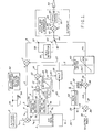
- analogue format as shown in Figure 1, it being understood that the same analogue format may also represent, in block diagram form, the program of a progammable digital computer wherein the various analogue inputs are converted to digital signals for digital processing and the various digital outputs are converted to analogue signals for driving the control surface servomotors and the like.
- the term voltage, digital word, etc. is to be interpreted as a signal, a measure or the like generic term.
- Switch blade 44 is in the position shown, contacting a terminal 42 since the altitude error is substantially larger than the actual altitude rate and therefore a null detector 59 responsive to these signals on leads 8 and 58 maintains the switch 44 in the position shown.
- a signal representative of the actual Mach number, M, of the aircraft is derived, for example, from a conventional air data computer and appears on a lead 28.
- a signal proportional to a selected Mach number for example, an entry by the human pilot on a suitable control panel or a computed Mach generated for example by a performance management computer to optimise fuel economy, appears on a lead 35, is supplied to a conventional summation device 36.
- the output of summation device 36 appears on a lead 37 and is a signal proportional to Mach error; that is, the difference between the selected Mach number and the actual Mach number of the aircraft AM.
- the signal at the terminal 29 is also impressed on a conventional rate generator 30, the output of which appears on a lead 31 and is a signal proportional to the time rate of change of actual Mach number, or Mach rate, M. Mach rate is multiplied in a multiplier 32 by a gain factor G2 to provide damping of the Mach number capture submode in a conventional manner.
- the output of the gain multiplier 32 appears on a lead 33 and is applied to conventional summation device 38 where it is algbebraically added to the Mach error signal on lead 37.
- the output of the summation device 38 appearing on lead 39 is supplied to the variable limiter 40 which has the characteristic curve 40a shown.
- the output of the variable limiter 40 which appears on lead 41, is a function of the variable T, the time-to-go to capture initiation as discussed above.
- the signal on lead 41 is supplied to a summation device 45 via a terminal 42 and the switch blade 44 and constitutes a pitch command for the autopilot as shown.
- the output of the summation device 45 appears on a lead 47 and is comprised of the signal at the switch 44 added algebraically with pitch angle and pitch rate on a lead 46, and elevator position feedback 51 in the well known conventional fashion.
- the signal on the lead 47 is applied to a pitch servo 48 to move an aircraft control surface 50 and, accordingly, to subject the aircraft to a corresponding corrective pitch rate again in a well-known fashion.
- variable limiter 40 is used to restrict the authority of any control law command signal of any of these automatic flight control system submodes.
- the apparatus so far described, except for the variable limiter 40 constitutes a generally conventional Mach-on-pitch control system wherein the aircraft pitch attitude is adjusted as a function of Mach error in order to maintain the selected Mach speed during the climb to the selected altitude.
- a signal proportional to a selected value of altitude is provided to an altitude selector 2 through mechanical links 53 by the manual setting of an altitude select dial 54, which may also be used to display the value of h s on a conventional display 52 as shown.
- a signal proportional to the actual altitude of the aircraft h a derived, for example, from the air data computer 1 is continuously supplied to a summation device 3 as is h s signal from the altitude selector 2.
- the output of summation device 3 on a lead 4 therefore represents the value (h - h ) which is, of course, the altitude deviation or altitude error h.
- the altitude error signal h e is supplied to a conventional absolute value detector 55 via a terminal 5 and lead 5a.
- the absolute value detector 55 operates in a conventional manner and may, of course, be either analogue or digital in nature.
- the output of the altitude error absolute value detector 55 appears on a lead 9 and is supplied as the numerator of a conventional divider 11.
- a signal proportional to the actual altitude rate of the aircraft h a is also continuously supplied on a lead 15 from the air data computer 1. This signal appears at a terminal 16 and is supplied to an altitude rate absolute value detector 46.
- the absolute value detector 56 is identical to the absolute value detector 55 previously described.
- the output of the absolute value detector 56 appears on a lead 10 and is supplied as the denominator of a divider 11.
- the output of the divider 11 on a lead 12 represents the absolute value quotient of the (h e /h a ). It can be seen then, that the absolute value of (h e /h a ) is a measure of the time required to reduce he to null at the present rate of climb or altitude rate of the aircraft. That is, (h e /h a ) represents the time required for the aircraft to achieve the selected altitude as hereinabove described.
- the signal proportional to the absolute value of altitude rate h a also appears on a lead 17 and it is supplied to a multiplier 18 which provides a gain adjustment Gl.
- Gl is proportional to the maximum normal acceleration which can be commanded by the control system as discussed above.
- the output of the gain multiplier 18 on a lead 19 is supplied to a limiter 20 the limit characteristic of which is illustrated.
- the limiter 20 performs the function of determining which segments of the commanded flight path for altitude capture will be asymptotic and/or which portions will be circular in nature. The details of this control will be discussed below.
- the output of the limiter 20 on a lead 21 represents the continuously computed value of K in the equation (3) above.
- the value of K as mentioned is proportional to the time required from the inception of the altitude capture manoeuvre to the final capture of the preselected altitude.
- the value of K appearing at a terminal 22, is supplied to the summation device 13 via a lead 23 and to a multiplier 26 via a lead 24.
- the output of summation device 13 on lead 14 represents the value or T in equation (2) aoove and is a measure of the time remaining or time-to-go before the commencement of the altitude capture manoeuvre.
- the value of T is supplied to the variable limiter 40 via the lead 14.
- the variable limiter 40 is conventionally constructed to permit the predetermined maximum allowable command to the pitch servo 48 when the value of T is larger than some predetermined value, for example 60 seconds.
- some predetermined value for example 60 seconds.
- the limits on the Mach command signal on the lead 39 are likewise reduced so that when the time T approaches zero, the limit is also near zero.
- h a will decrease causing the output of gain multiplier 18 on lead 19 to decrease in a like fashion.
- the output of the limiter 20 (the value of K) will be continuously proportional to the altitude rate h a This action results in the command of a circular flight path through the action of Kh a which appears on the output of the multiplier 26 on lead 27.
- the limiter 20 adapts the capture flight path to whatever altitude rate the aircraft is flying at capture initiation and accomplishes this without exceeding the maximum g level set by the gain multiplier 18.
- Figure 2 is a graph of altitude deviation h e against altitude rate h a .
- Lines 61 and 62 represent solutions to equation (1) above, whereas line 61 represents a maximum constant value of K, and line 62 represents a minimum constant value of K. These solutions will result in asymptotic flight paths to the preselected altitude.
- Line 60 represents the solution to the above equation where K is proportional to h a and results in a flight path circular in nature to the preselected altitude.
- the action of the limiter 20 is such as to command the flight path 61 (which is defined by the maximum limit) until the value of h becomes less than the value a corresponding to point 63.
- the value of K varies with h a and the commanded path is circular-in nature and remains thus until h becomes less than the value corresponding to point 64.
- the value of K is limited to a minimum constant value and an asymptotic path is commanded until the preselected altitude has been achieved.
- the shape of the commanded flight path is dependent on the value of h when the altitude manoeuvre commences. If a the altitude rate h a causes the signal on the lead 19 to exceed the maximum value allowed by the limiter 20, the commanded flight path will initially be asymptotic, then circular and finally asymptotic once again. If the initial signal on lead 19 is less than the maximum allowed by the limiter 20, the commanded flight path will initially be circular and then asymptotic. If the signal on the lead 19 is initially less than the minimum allowed by the limiter 20, the commanded flight path will be solely asymptotic. All of these flight paths will be achieved without exceeding the predetermined maximum normal acceleration or g level.
- Figure 2 is a graph illustrative of altitude deviation he and elapsed time from the commencement of the altitude capture manoeuvre.
- Line 65 illustrates the commanded flight path for a constant minimum value of K . It will be seen that it asymptotically approaches the selected altitude with no circular portion.
- Line 66 illustrates the commanded flight path when the value of K remains below the maximum limit of the limiter 20 and a circular capture manoeuvre results until the value of K reaches the minimum when an asymptotic path is commanded.
- Line 67 illustrates the commanded flight path where K is initially the maximum constant, then varies with h a and finally is the minimum constant. Thus, the flight path varies from asymptotic to circular and then finally to asymptotic again.
Landscapes
- Engineering & Computer Science (AREA)
- Aviation & Aerospace Engineering (AREA)
- Radar, Positioning & Navigation (AREA)
- Remote Sensing (AREA)
- Physics & Mathematics (AREA)
- General Physics & Mathematics (AREA)
- Automation & Control Theory (AREA)
- Control Of Position, Course, Altitude, Or Attitude Of Moving Bodies (AREA)
- Navigation (AREA)
- Traffic Control Systems (AREA)
- Feedback Control In General (AREA)
Applications Claiming Priority (2)
| Application Number | Priority Date | Filing Date | Title |
|---|---|---|---|
| US06/476,090 US4609988A (en) | 1983-03-17 | 1983-03-17 | Automatic prediction and capture of a preselected altitude for aircraft |
| US476090 | 1995-06-07 |
Publications (3)
| Publication Number | Publication Date |
|---|---|
| EP0122718A2 true EP0122718A2 (fr) | 1984-10-24 |
| EP0122718A3 EP0122718A3 (en) | 1985-07-31 |
| EP0122718B1 EP0122718B1 (fr) | 1989-01-18 |
Family
ID=23890468
Family Applications (1)
| Application Number | Title | Priority Date | Filing Date |
|---|---|---|---|
| EP84301723A Expired EP0122718B1 (fr) | 1983-03-17 | 1984-03-14 | Appareillage et méthode pour la commande automatique du vol d'un aéronef |
Country Status (4)
| Country | Link |
|---|---|
| US (1) | US4609988A (fr) |
| EP (1) | EP0122718B1 (fr) |
| JP (1) | JPH078679B2 (fr) |
| DE (1) | DE3476283D1 (fr) |
Cited By (5)
| Publication number | Priority date | Publication date | Assignee | Title |
|---|---|---|---|---|
| EP0224279A1 (fr) * | 1985-11-26 | 1987-06-03 | The Boeing Company | Appareil et méthode pour engendrer des commandes de vol utilisant une régulation à gain de contre-réaction non-linéaire |
| EP0127390B1 (fr) * | 1983-05-20 | 1989-03-15 | Honeywell Inc. | Appareil de commande de décélération pour un avion |
| DE3608108C1 (de) * | 1986-03-12 | 1990-06-07 | Diehl Gmbh & Co | Verfahren zur Abwehr von Flugobjekten |
| US7774106B2 (en) | 2006-12-22 | 2010-08-10 | Pratt - Whitney Canada Corp. | Cruise control FADEC logic |
| US7949440B2 (en) | 2006-12-22 | 2011-05-24 | Embraer-Empresa Brasileira De Aeronautica S.A. | Aircraft cruise speed control |
Families Citing this family (7)
| Publication number | Priority date | Publication date | Assignee | Title |
|---|---|---|---|---|
| US4924400A (en) * | 1988-09-01 | 1990-05-08 | United Technologies Corporation | Arrangement for controlling the performance of bob-up/bob-down maneuvers by a helicopter |
| FR2754364B1 (fr) * | 1996-10-03 | 1998-11-27 | Aerospatiale | Procede et dispositif de guidage vertical d'un aeronef |
| FR2845170B1 (fr) * | 2002-10-01 | 2005-09-23 | Thales Sa | Procede d'aide a la navigation d'un aeronef et dispositif correspondant |
| US6819266B2 (en) * | 2002-10-07 | 2004-11-16 | Safe Flight Instrument Corporation | System and method for reducing the speed of an aircraft |
| JP5594996B2 (ja) * | 2009-09-14 | 2014-09-24 | 三菱重工業株式会社 | 航空機の操縦システム |
| ES2694427T3 (es) * | 2013-06-06 | 2018-12-20 | The Boeing Company | Método y sistema de control de velocidad de la aeronave |
| CN115826613B (zh) * | 2022-11-11 | 2025-09-23 | 中国航空工业集团公司西安飞行自动控制研究所 | 一种考虑飞行器路径截获能力的俯仰控制模式切换方法 |
Family Cites Families (12)
| Publication number | Priority date | Publication date | Assignee | Title |
|---|---|---|---|---|
| US3240446A (en) | 1963-10-15 | 1966-03-15 | Sperry Rand Corp | Preselect altitude control system for aircraft |
| US3510092A (en) * | 1967-07-28 | 1970-05-05 | Honeywell Inc | Craft altitude control apparatus |
| US3524612A (en) | 1967-09-27 | 1970-08-18 | Honeywell Inc | Craft altitude control apparatus |
| US3545703A (en) * | 1967-11-01 | 1970-12-08 | Bendix Corp | System for controlling flight of aircraft to attain a predetermined altitude |
| US3604908A (en) * | 1969-05-19 | 1971-09-14 | Sperry Rand Corp | Landing control system for aircraft |
| GB1270754A (en) * | 1970-04-03 | 1972-04-12 | Bendix Corp | System for controlling vertical flight of aircraft |
| US3715718A (en) * | 1970-08-11 | 1973-02-06 | Sundstrand Data Control | Ground proximity warning system utilizing radio and barometric altimeter combination |
| US3691356A (en) * | 1970-12-10 | 1972-09-12 | Sperry Rand Corp | Speed command and throttle control system for aircraft |
| US3735274A (en) * | 1971-08-10 | 1973-05-22 | Gen Motors Corp | Thermocouple signal amplifier |
| US4019702A (en) * | 1975-11-13 | 1977-04-26 | The Boeing Company | Method and apparatus for guiding a jet aircraft in a noise-abated post-takeoff climb |
| US4114842A (en) * | 1977-03-28 | 1978-09-19 | Sperry Rand Corporation | Acceleration limited preselect altitude capture and control |
| US4377848A (en) | 1980-10-16 | 1983-03-22 | Sperry Corporation | Altitude capture mode for aircraft automatic flight control system |
-
1983
- 1983-03-17 US US06/476,090 patent/US4609988A/en not_active Expired - Lifetime
-
1984
- 1984-02-02 JP JP59017631A patent/JPH078679B2/ja not_active Expired - Lifetime
- 1984-03-14 DE DE8484301723T patent/DE3476283D1/de not_active Expired
- 1984-03-14 EP EP84301723A patent/EP0122718B1/fr not_active Expired
Cited By (6)
| Publication number | Priority date | Publication date | Assignee | Title |
|---|---|---|---|---|
| EP0127390B1 (fr) * | 1983-05-20 | 1989-03-15 | Honeywell Inc. | Appareil de commande de décélération pour un avion |
| EP0224279A1 (fr) * | 1985-11-26 | 1987-06-03 | The Boeing Company | Appareil et méthode pour engendrer des commandes de vol utilisant une régulation à gain de contre-réaction non-linéaire |
| DE3608108C1 (de) * | 1986-03-12 | 1990-06-07 | Diehl Gmbh & Co | Verfahren zur Abwehr von Flugobjekten |
| US5050818A (en) * | 1986-03-12 | 1991-09-24 | Diehl Gmbh & Co. | Method for the repulsing of airborne objects |
| US7774106B2 (en) | 2006-12-22 | 2010-08-10 | Pratt - Whitney Canada Corp. | Cruise control FADEC logic |
| US7949440B2 (en) | 2006-12-22 | 2011-05-24 | Embraer-Empresa Brasileira De Aeronautica S.A. | Aircraft cruise speed control |
Also Published As
| Publication number | Publication date |
|---|---|
| EP0122718A3 (en) | 1985-07-31 |
| JPH078679B2 (ja) | 1995-02-01 |
| JPS59171795A (ja) | 1984-09-28 |
| DE3476283D1 (en) | 1989-02-23 |
| US4609988A (en) | 1986-09-02 |
| EP0122718B1 (fr) | 1989-01-18 |
Similar Documents
| Publication | Publication Date | Title |
|---|---|---|
| EP0028435B1 (fr) | Système de guidage d'avion en montée | |
| US4924401A (en) | Aircraft ground collision avoidance and autorecovery systems device | |
| EP0253614B1 (fr) | Système de commande de la trajectoire verticale et de la vitesse par rapport à l'air d'un avion | |
| EP0034874B1 (fr) | Système de commande d'atterrissage d'avion | |
| US5023793A (en) | Apparatus and method for dynamic compensation of a propeller pitch speed control governor | |
| US5571953A (en) | Method and apparatus for the linear real time estimation of an aircraft center of gravity | |
| EP0549014B1 (fr) | Méthode et dispositif de contrÔle de la poussée d'un aéronef pendant le vol de montée | |
| US3604908A (en) | Landing control system for aircraft | |
| US4300200A (en) | Helicopter airspeed indicating system | |
| EP0122718B1 (fr) | Appareillage et méthode pour la commande automatique du vol d'un aéronef | |
| US4004756A (en) | Automatic flight control means for rotary wing aircraft | |
| EP0189239B1 (fr) | Régulation de la trajectoire de vol de descente pour aéronefs | |
| US4044975A (en) | Aircraft speed command system | |
| US4763266A (en) | Aircraft flight command and display system | |
| EP0235964A2 (fr) | Procédé et appareil de guidage d'avion en zone de cisaillement du vent | |
| EP0150122A2 (fr) | Commande de la vitesse de croisière d'un avion durant une capture d'altitude | |
| US5020747A (en) | Method and apparatus for controlling flare engagement height in automatic landing systems | |
| US4488235A (en) | Speed control system for aircraft | |
| US3059880A (en) | Terminal predication aircraft landing system | |
| EP0229197B1 (fr) | Système de commande de vol et de visualisation des soutes de vent | |
| EP0224279A1 (fr) | Appareil et méthode pour engendrer des commandes de vol utilisant une régulation à gain de contre-réaction non-linéaire | |
| US6898491B2 (en) | Process and device for automatically controlling the thrust of at least one engine of an aircraft during a phase of horizontal flight at stabilized speed | |
| US4563743A (en) | Maneuver-force gradient system | |
| US5089968A (en) | Ground effects compensated real time aircraft body angle of attack estimation | |
| EP0444541B1 (fr) | Méthode et appareillage pour la transition sans secousses d'une commande de vitesse par rapport à l'air à une commande de nombre de Mach d'un avion |
Legal Events
| Date | Code | Title | Description |
|---|---|---|---|
| PUAI | Public reference made under article 153(3) epc to a published international application that has entered the european phase |
Free format text: ORIGINAL CODE: 0009012 |
|
| AK | Designated contracting states |
Designated state(s): DE FR GB IT |
|
| PUAL | Search report despatched |
Free format text: ORIGINAL CODE: 0009013 |
|
| AK | Designated contracting states |
Designated state(s): DE FR GB IT |
|
| 17P | Request for examination filed |
Effective date: 19850917 |
|
| 17Q | First examination report despatched |
Effective date: 19870506 |
|
| RAP1 | Party data changed (applicant data changed or rights of an application transferred) |
Owner name: HONEYWELL INC. |
|
| ITF | It: translation for a ep patent filed | ||
| GRAA | (expected) grant |
Free format text: ORIGINAL CODE: 0009210 |
|
| AK | Designated contracting states |
Kind code of ref document: B1 Designated state(s): DE FR GB IT |
|
| REF | Corresponds to: |
Ref document number: 3476283 Country of ref document: DE Date of ref document: 19890223 |
|
| ET | Fr: translation filed | ||
| RAP2 | Party data changed (patent owner data changed or rights of a patent transferred) |
Owner name: HONEYWELL INC. |
|
| PLBI | Opposition filed |
Free format text: ORIGINAL CODE: 0009260 |
|
| 26 | Opposition filed |
Opponent name: MESSERSCHMITT - BOELKOW - BLOHM GMBH, OTTOBRUNN Effective date: 19890930 |
|
| PLAB | Opposition data, opponent's data or that of the opponent's representative modified |
Free format text: ORIGINAL CODE: 0009299OPPO |
|
| R26 | Opposition filed (corrected) |
Opponent name: DEUTSCHE AIRBUS GMBH HAMBURG Effective date: 19890930 |
|
| PLBN | Opposition rejected |
Free format text: ORIGINAL CODE: 0009273 |
|
| STAA | Information on the status of an ep patent application or granted ep patent |
Free format text: STATUS: OPPOSITION REJECTED |
|
| 27O | Opposition rejected |
Effective date: 19920727 |
|
| ITTA | It: last paid annual fee | ||
| REG | Reference to a national code |
Ref country code: GB Ref legal event code: IF02 |
|
| PGFP | Annual fee paid to national office [announced via postgrant information from national office to epo] |
Ref country code: GB Payment date: 20030204 Year of fee payment: 20 |
|
| PGFP | Annual fee paid to national office [announced via postgrant information from national office to epo] |
Ref country code: FR Payment date: 20030303 Year of fee payment: 20 |
|
| PGFP | Annual fee paid to national office [announced via postgrant information from national office to epo] |
Ref country code: DE Payment date: 20030331 Year of fee payment: 20 |
|
| PG25 | Lapsed in a contracting state [announced via postgrant information from national office to epo] |
Ref country code: GB Free format text: LAPSE BECAUSE OF EXPIRATION OF PROTECTION Effective date: 20040313 |
|
| REG | Reference to a national code |
Ref country code: GB Ref legal event code: PE20 |