EP0549014B1 - Méthode et dispositif de contrÔle de la poussée d'un aéronef pendant le vol de montée - Google Patents
Méthode et dispositif de contrÔle de la poussée d'un aéronef pendant le vol de montée Download PDFInfo
- Publication number
- EP0549014B1 EP0549014B1 EP92203661A EP92203661A EP0549014B1 EP 0549014 B1 EP0549014 B1 EP 0549014B1 EP 92203661 A EP92203661 A EP 92203661A EP 92203661 A EP92203661 A EP 92203661A EP 0549014 B1 EP0549014 B1 EP 0549014B1
- Authority
- EP
- European Patent Office
- Prior art keywords
- value
- aircraft
- climb
- thrust level
- engine
- Prior art date
- Legal status (The legal status is an assumption and is not a legal conclusion. Google has not performed a legal analysis and makes no representation as to the accuracy of the status listed.)
- Expired - Lifetime
Links
Images
Classifications
-
- G—PHYSICS
- G05—CONTROLLING; REGULATING
- G05D—SYSTEMS FOR CONTROLLING OR REGULATING NON-ELECTRIC VARIABLES
- G05D1/00—Control of position, course, altitude or attitude of land, water, air or space vehicles, e.g. using automatic pilots
- G05D1/04—Control of altitude or depth
- G05D1/06—Rate of change of altitude or depth
- G05D1/0607—Rate of change of altitude or depth specially adapted for aircraft
- G05D1/0653—Rate of change of altitude or depth specially adapted for aircraft during a phase of take-off or landing
- G05D1/0661—Rate of change of altitude or depth specially adapted for aircraft during a phase of take-off or landing specially adapted for take-off
Definitions
- the present invention relates to apparatus and methods for controlling aircraft engine thrust as described in the preamble of claim 1 and 6.
- Such a method and apparatus are known from for example U.S. patent No. 4,019,702 by Annin (assigned to the assignee of the present application) discloses a pilot guidance system that displays pitch and speed commands during takeoff climb for engine noise abatement purposes.
- the throttle be positioned automatically during this transition to avoid the aforementioned trial and error procedure and to allow the pilot to direct his attention to other matters.
- U.S. Patent No. 4,662,171 by Jackson et al discloses an autothrottle control system for automatically increasing the thrust of a working engine(s) of an aircraft if power is lost on a different engine while the aircraft is operating at reduced thrust during a takeoff noise abatement maneuver.
- the present invention pertains to a method and apparatus for adjusting aircraft engine thrust as described in claim 1 and 6.
- the method includes the steps of selecting a gradient for climbing the aircraft.
- the method also includes the steps of flying the aircraft at a first climb attitude. This is followed by the steps of reducing the pitch attitude of the first climb attitude to a second climb attitude, and then automatically adjusting the engine thrust during this pitch attitude reduction so that during a second climb segment the aircraft climbs at the selected climb gradient while flying at the selected airspeed.
- the present invention operates to automatically reduce aircraft thrust when a pre-selected noise abatement altitude has been reached after takeoff.
- the present invention then controls engine thrust so that if the pilot maintains a "recommended" climbout airspeed, the aircraft automatically tracks a selected noise abatement climb gradient.
- This recommended climbout airspeed (usually V2 + 27,8 km [15 knots]) is a function of aircraft weight and flap setting and is independent of noise abatement considerations.
- the present control system Upon nearing the noise abatement altitude, the present control system starts reducing engine thrust to a level necessary to maintain the noise abatement climb gradient at the recommended climbout airspeed.
- the pilot simply adjusts the control column to maintain the recommended climbout airspeed. In this manner, the pilot need only reduce the pitch attitude of the aircraft by operation of the control column.
- the control system of the present invention operates to automatically reduce the thrust of the aircraft engine so as to maintain the preselected noise abatement climb gradient (typically between one and two percent).
- the aircraft pitch attitude control (and airspeed control through pitch attitude adjustments) is accomplished in a conventional manner by the aircraft autopilot system.
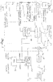
- FIG. 1 shows the control system of the present invention, generally indicated at 20, for regulating the thrust output of a conventional aircraft engine 22.
- the control system outputs a signal to a conventional throttle servo 24 which automatically positions a conventional throttle 26 which in turn is linked to the engine 22 in a conventional manner.
- a noise abatement command signal generated by the control system 20 causes the throttle to be automatically positioned so that predetermined noise abatement climb gradient is maintained.
- control system 20 is implemented in a conventional autothrottle digital computer.
- a conventional takeoff thrust command signal is output from a conventional flight management computer 30 (FIG. 1).
- the FMC 30 stores assigned route of flight, assigned altitudes, and temperature information, and from this information generates the takeoff thrust command signal in a conventional manner.
- the takeoff thrust command signal is fed into the control system 20 through a switch 32, which in turn is followed by a subtractor 36, before proceeding on to the throttle servo 24. With the switch 32 in the solid line "up" position shown in FIG. 1, the noise abatement autothrottle is inactive and operation as just described is purely conventional.
- the switch 32 moves to the "down" position shown in dashed lines (FIG. 1) which permits a noise abatement thrust signal (instead of the takeoff thrust command signal) to be fed to the throttle servo 24.
- the noise abatement thrust signal is generated by a controller 37 to be described later.
- the selected noise abatement altitude and selected climb gradient (G s ) are entered by the pilot at a conventional control display unit (CDU) 38 located in the airplane cockpit.
- the control display unit 38 includes a display screen and alphanumeric keypad (both not shown) which permits manual selection of a takeoff data page where the pilot may enter the noise abatement altitude and selected climb gradient prior to takeoff.
- the position of throttle 26 is regulated by an error feedback loop 40 which includes an engine RPM-to-thrust converter 42.
- an engine RPM signal which is output from an engine sensor (not shown) is converted to a thrust signal for subtraction from the takeoff thrust command or noise abatement thrust command (depending upon the position of switch 32) at the subtractor 36.
- Conversion of engine RPM to thrust is accomplished using known equations and is a function of airplane mach number and outside air temperature which are obtained from a conventional air data computer 44 using signals from conventional temperature and pressure sensors.
- the control system 20 has two possible modes of operation.
- a first mode the selected climb gradient (G s ) signal from CDU 38 is fed through a switch 43 which when in the dotted line position (in FIG. 1) sends the (G s ) signal to FMC 30 where it is converted in a conventional manner) using lookup tables which include airplane gross weight, temperature and airport pressure altitude) to an engine RPM signal.
- This RPM signal is then converted to a thrust value at an RPM-to-thrust converter 41.
- a minimum safe climb gradient value is stored at a memory block 45.
- the minimum safe climb gradient signal is fed through a switch 46 (which is in the dotted line position) to the controller 37 where it is converted to a minimum safe thrust signal (in a manner to be described later).
- the noise abatement thrust value is compared to the minimum safe thrust signal generated from the controller 37 at a comparator 52 and the larger value is fed to the switch 32.
- switches 43 and 46 are hardwired in the solid line positions shown in FIG. 1.
- the selected climb gradient G s is fed directly to the controller 37 which computes the required thrust in a manner to be described later.
- the resulting required thrust signal is fed through the comparator 52 to the switch 32.
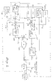
- the controller 37 for generating the noise abatement thrust signal or minimum safe thrust signal
- the controller 37 is a software program stored in the conventional autothrottle computer.
- the controller 37 operates by generating either the noise abatement thrust signal or the minimum safe thrust signal in the form of a predicted thrust (T p ) required for maintaining the selected climb gradient (G s ) or the minimum safe climb gradient, as the case may be.
- T p predicted thrust
- G s selected climb gradient
- the minimum safe climb gradient as the case may be.
- the operation of controller 37 will be discussed with reference to the generation of a noise abatement reference thrust signal as a function of the selected climb gradient signal (G s ), however generation of a minimum safe thrust signal as a function of the minimum safe climb gradient signal occurs in an identical manner.
- IRU inertial reference unit
- the quantity qS A cos P is calculated at a multiplier 62 and the resulting product is divided into airplane weight at a divider 64 to obtain C l .
- the coefficient of drag, C d is obtained from a drag polar lookup table 66 which contains values of C d as functions of airplane coefficient of lift C l for various flap settings (obtained from a conventional flap position sensor 68).
- the values of C d are obtained from drag polars (referenced to an airplane in level flight). However, these drag polars are used to generate values of C d for an airplane in a slight climb.
- an error loop indicated at 70 is provided.
- an error term G e (sometimes known as potential gamma) is generated by subtracting (at a subtractor 74) from the selected noise abatement climb gradient (G s ) a sum equal to the measured climb gradient (G m ) plus an acceleration term (a).
- the purpose of the acceleration term is to assist the aircraft in flying a constant climb gradient by making G e independent of any aircraft airspeed changes due to aircraft maneuvering. That is, during the climbout the pilot controls the airspeed by adjusting the pitch attitude of the aircraft.
- the present controller operates to adjust the aircraft thrust so that the aircraft follows the selected noise abatement climb gradient.
- the acceleration correction term (a) would not be necessary if the pilot flew the climb at exactly the recommended climb airspeed. However, if there were no acceleration correction term and the pilot did not exactly hold the recommended climb airspeed, the error term G e instead of converging to zero, could, in fact, diverge so that the aircraft would not follow the selected climb gradient.
- the aircraft will decelerate (negative acceleration).
- the negative acceleration term (-a) is added to the steeper measured climb gradient (G m ) at adder 76 so that the resulting "corrected" measured climb gradient (fed to subtractor 74) is reduced to what the measured climb gradient would have been had the pilot maintained the recommended climb airspeed.
- the measured aircraft acceleration (a) is a conventional output from a conventional autothrottle computer 78 and is equal to the aircraft body axis acceleration minus pitch attitude which has been scaled using a convenient scalar such as radians or feet per second.
- the error term G e from subtractor 74 is sent through a switch 77 to a K Ge /S integrator 79 (where K Ge is the gain constant and s is a Laplace operator) having a gain of about 0.01.
- Switch 77 is moved to the solid line closed position (as shown in FIG. 2) in response to a signal from CDU 38 when the airplane reaches the noise abatement altitude.
- the purpose of switch 77 is to avoid initiating integrator 79 prior to calculating the proper value of G e , or in other words, before the aircraft has settled on the noise abatement climb gradient.
- the gain of integrator 79 is chosen so that the error term is slowly corrected without substantially affecting the dynamics of the error loop.
- the resulting adjusted error term G ek is added to the selected climb gradient G s (from CDU 38) at an adder 80 to generate a commanded climb gradient term (G c ).
- G c x C l of equation #7 is generated at a multiplier 83 (downstream of adder 80).
- the resulting product from multiplier 83 is added to C d (from lookup table 66) at an adder 84, and the resulting sum is multiplied by the product qS A at a downstream multiplier 86 to generate the noise abatement thrust signal for use as previously described with reference to FIG. 1.
Landscapes
- Engineering & Computer Science (AREA)
- Aviation & Aerospace Engineering (AREA)
- Radar, Positioning & Navigation (AREA)
- Remote Sensing (AREA)
- Physics & Mathematics (AREA)
- General Physics & Mathematics (AREA)
- Automation & Control Theory (AREA)
- Control Of Position, Course, Altitude, Or Attitude Of Moving Bodies (AREA)
Claims (10)
- Procédé d'ajustement de la poussée d'un réacteur d'aéronef, le procédé comprenant les étapes suivantes :a) la sélection d'un premier gradient de montée (Gs) pour l'aéronef,b) le vol de l'aéronef avec une première attitude en tangage pendant le premier segment de montée,c) la réduction d'une première attitude de tangage de l'aéronef à la fin du premier segment de montée à une altitude prédéterminée (38) de réduction de bruit, depuis la première attitude de tangage, caractérisé pard) le vol de l'aéronef à une vitesse aérodynamique choisie pendant un second segment de montée,e) la mesure (82) d'un gradient de montée (Gm) de l'aéronef,f) la détermination (37) d'un niveau de poussée de référence par détermination d'une première valeur qui est fonction du gradient choisi de montée, par détermination d'une seconde valeur qui est indépendante des changements de la vitesse aérodynamique de l'aéronef par détermination d'une valeur d'accélération de l'aéronef et par combinaison de la valeur d'accélération et du gradient mesuré de montée, par détermination d'une différence entre la première valeur et la seconde valeur pour la création (74) d'une valeur d'erreur (Ge), et par conversion de la valeur d'erreur en un niveau de poussée de référence,g) la détection (42) d'un niveau réel de poussée du réacteur, eth) l'ajustement (24) du niveau réel de poussée du réacteur de manière que le niveau réel de poussée soit proche du niveau de poussée de référence pendant la réduction d'attitude en tangage afin que l'aéronef monte avec le gradient choisi de montée pendant le second segment de montée.
- Procédé selon la revendication 1, comprenant en outre l'étape de vol de l'aéronef à la vitesse aérodynamique choisie pendant le premier segment de montée.
- Procédé selon la revendication 1, dans lequel le gradient choisi de montée est un gradient de montée de réduction de bruit.
- Procédé selon la revendication 1, dans lequel l'étape de conversion de la valeur d'erreur en une valeur de poussée comprend les étapes suivantes :a) la combinaison (80) de la valeur d'erreur à la première valeur pour la création d'une troisième valeur,b) la multiplication (83) de la troisième valeur par une valeur qui est fonction d'un coefficient de la valeur de portance de l'aéronef afin qu'une quatrième valeur soit créée, etc) la combinaison (84) de la quatrième valeur à une valeur qui est fonction de la valeur du coefficient de traînée de l'aéronef.
- Procédé selon la revendication 1, dans lequel l'étape d'ajustement automatique comprend les étapes suivantes :a) la détermination d'un premier niveau de poussée qui est fonction du gradient choisi de montée (Gs),b) la détermination (45) d'une valeur minimale de gradient de montée,c) la comparaison (52) de la valeur minimale de gradient de montée à la première valeur et la sélection (32) de celle des deux valeurs qui est la plus grande pour la création d'un niveau de poussée de référence,d) la détection (42) d'un niveau réel de poussée du réacteur,e) la comparaison (36) du niveau réel de poussée du réacteur au niveau de poussée de référence, etf) l'ajustement (24) du niveau réel de poussée du réacteur de manière que le niveau réel de poussée soit proche du niveau de poussée de référence.
- Appareil d'ajustement de la poussée d'un réacteur d'aéronef, l'appareil comprenant :a) un dispositif de sélection d'un premier gradient de montée de l'aéronef,b) un dispositif destiné à commander le vol de l'aéronef avec une première attitude en tangage pendant un premier segment de montée,c) un dispositif de réduction d'une première attitude en tangage de l'aéronef à la fin du premier segment de montée à l'altitude prédéterminée (38) de réduction de bruit depuis la première attitude en tangage, caractérisé pard) un dispositif de commande de vol de l'aéronef à une vitesse aérodynamique choisie pendant un second segment de montée,e) un dispositif de mesure du gradient de montée (Gm) de l'aéronef,f) un dispositif (37) de détermination d'un niveau de poussée de référence comprenant un dispositif de détermination d'une première valeur qui est fonction du gradient choisi de montée, un dispositif de détermination d'une seconde valeur qui est indépendante des changements de vitesse aérodynamique de l'aéronef par détermination d'une valeur d'accélération de l'aéronef, et par combinaison de la valeur d'accélération et du gradient mesuré de montée, un dispositif de détermination d'une différence entre la première valeur et la seconde valeur, destiné à créer (74) une valeur d'erreur (Ge), et un dispositif de conversion de la valeur d'erreur en un niveau de poussée de référence,g) un dispositif (42) de détection d'un niveau réel de poussée du réacteur, eth) un dispositif (24) d'ajustement du niveau réel de poussée du réacteur de manière que le niveau réel de poussée soit proche du niveau de poussée de référence pendant la réduction de l'attitude en tangage afin que l'aéronef monte avec le gradient choisi de montée pendant le second segment de montée.
- Appareil selon la revendication 6, comprenant en outre un dispositif de commande de vol de l'aéronef à la vitesse aérodynamique choisie pendant le premier segment de montée.
- Appareil selon la revendication 6, dans lequel le dispositif d'ajustement automatique comporte :a) un dispositif de détermination d'un premier niveau de poussée qui est fonction du gradient choisi de montée (Gs),b) un dispositif (45) de détermination d'une valeur minimale de gradient de montée,c) un dispositif de comparaison (52) de la valeur du gradient minimal de montée à la première valeur et de sélection (32) de celle des deux valeurs qui est la plus grande pour la création d'un niveau de poussée de référence,d) un dispositif (42) de détection d'un niveau réel de poussée du réacteur,e) un dispositif (36) de comparaison du niveau réel de poussée du réacteur au niveau de poussée de référence, etf) un dispositif (24) d'ajustement du niveau réel de poussée du réacteur de manière que ce niveau réel de poussée soit proche du niveau de poussée de référence.
- Procédé d'ajustement de la poussée d'un réacteur d'aéronef selon la revendication 1, caractérisé para) la détermination d'un niveau de gradient minimal de montée (45),b) la comparaison (52) du niveau de gradient minimal de montée au niveau de poussée de montée et la sélection (32) de celui des deux niveaux qui est le plus grand pour la création d'un niveau de poussée de référence,c) la détection (42) d'un niveau réel de poussée du réacteur, etd) l'ajustement (24) du niveau réel de poussée du réacteur de manière que le niveau réel de poussée soit proche du niveau de poussée de référence.
- Appareil d'ajustement de la poussée d'un réacteur d'aéronef selon la revendication 6, caractérisé para) un dispositif (45) de détermination d'un niveau de gradient minimal de montée,b) un dispositif de comparaison (52) du niveau de gradient minimal de montée au niveau de poussée de montée et de sélection (32) de celui des deux niveaux qui est le plus grand pour la création d'un niveau de poussée de référence,c) un dispositif (42) de détection d'un niveau réel de poussée du réacteur, etd) un dispositif (24) d'ajustement du niveau réel de poussée du réacteur de manière que le niveau réel de poussée soit proche du niveau de poussée de référence.
Applications Claiming Priority (2)
| Application Number | Priority Date | Filing Date | Title |
|---|---|---|---|
| US811724 | 1991-12-23 | ||
| US07/811,724 US5299765A (en) | 1991-12-23 | 1991-12-23 | Apparatus and methods for controlling aircraft thrust during a climb |
Publications (2)
| Publication Number | Publication Date |
|---|---|
| EP0549014A1 EP0549014A1 (fr) | 1993-06-30 |
| EP0549014B1 true EP0549014B1 (fr) | 1996-04-24 |
Family
ID=25207376
Family Applications (1)
| Application Number | Title | Priority Date | Filing Date |
|---|---|---|---|
| EP92203661A Expired - Lifetime EP0549014B1 (fr) | 1991-12-23 | 1992-11-26 | Méthode et dispositif de contrÔle de la poussée d'un aéronef pendant le vol de montée |
Country Status (3)
| Country | Link |
|---|---|
| US (1) | US5299765A (fr) |
| EP (1) | EP0549014B1 (fr) |
| DE (1) | DE69210193T2 (fr) |
Families Citing this family (27)
| Publication number | Priority date | Publication date | Assignee | Title |
|---|---|---|---|---|
| US6691004B2 (en) * | 1995-07-31 | 2004-02-10 | Honeywell International, Inc. | Method for determining a currently obtainable climb gradient of an aircraft |
| US6062513A (en) * | 1998-09-14 | 2000-05-16 | The Boeing Company | Total energy based flight control system |
| US6885340B2 (en) * | 2000-02-29 | 2005-04-26 | Rannoch Corporation | Correlation of flight track data with other data sources |
| US6633259B1 (en) * | 1999-03-05 | 2003-10-14 | Rannuch Corporation | Method and apparatus for improving utility of automatic dependent surveillance |
| FR2854128B1 (fr) * | 2003-04-22 | 2006-04-07 | Airbus France | Indicateur de pilotage pour un aeronef, en particulier un avion de transport, destine a fournir la poussee engendree par au moins un moteur de l'aeronef |
| US6880784B1 (en) * | 2003-05-08 | 2005-04-19 | Supersonic Aerospace International, Llc | Automatic takeoff thrust management system |
| US6945500B2 (en) * | 2003-08-15 | 2005-09-20 | Skycorp, Inc. | Apparatus for a geosynchronous life extension spacecraft |
| US6886786B1 (en) * | 2003-10-10 | 2005-05-03 | The Boeing Company | Engine thrust management—new design architecture |
| GB0415618D0 (en) * | 2004-07-13 | 2004-08-18 | Rolls Royce Plc | Aircraft takeoff |
| US20070260424A1 (en) * | 2006-05-05 | 2007-11-08 | Harold Brown | Methods and apparatus for estimating engine thrust |
| US7788013B2 (en) * | 2006-07-03 | 2010-08-31 | Textron System Corporation | Techniques for remotely adjusting a portion of an airplane engine |
| US7584028B2 (en) * | 2006-11-14 | 2009-09-01 | The Boeing Company | Methods and systems for implementing location based noise abatement procedures |
| US8670881B2 (en) * | 2007-03-14 | 2014-03-11 | General Electric Company | Flight management system for generating variable thrust cutback during aircraft departure |
| US8380371B2 (en) * | 2007-03-14 | 2013-02-19 | General Electric Company | Method of generating variable thrust cutback during aircraft departure |
| US8131410B2 (en) * | 2007-06-15 | 2012-03-06 | The Boeing Company | Quiet climb crew interface |
| US7861578B2 (en) * | 2008-07-29 | 2011-01-04 | General Electric Company | Methods and systems for estimating operating parameters of an engine |
| FR2946016B1 (fr) * | 2009-05-29 | 2012-09-28 | Airbus France | Systeme pour la commande d'au moins un moteur d'aeronef et aeronef comportant un tel systeme de commande. |
| FR2946017B1 (fr) * | 2009-05-29 | 2012-09-28 | Airbus France | Systeme pour la commande d'au moins un moteur d'aeronef et aeronef comportant un tel systeme de commande. |
| EP3741679B1 (fr) | 2013-08-28 | 2021-12-29 | Raytheon Technologies Corporation | Équilibrage de poussée d'aéronef à multiples moteurs |
| US10112722B2 (en) | 2015-01-15 | 2018-10-30 | Unison Industries Llc | Power control for propeller-driven aircraft |
| US10227933B2 (en) * | 2015-02-12 | 2019-03-12 | United Technologies Corporation | Aircraft power setting trims for life extension |
| US9696724B1 (en) * | 2016-04-22 | 2017-07-04 | Rockwell Collins, Inc. | Takeoff automating system, device, and method |
| US10399689B2 (en) | 2017-06-07 | 2019-09-03 | Ge Aviation Systems Llc | Optimizing aircraft control based on noise abatement volumes |
| US10671092B2 (en) * | 2017-10-20 | 2020-06-02 | The Boeing Company | Airplane climb thrust optimization |
| US11216011B2 (en) | 2018-03-16 | 2022-01-04 | Embraer S.A. | Optimized trajectory to noise improvement with auto-takeoff |
| US11391218B2 (en) * | 2019-03-22 | 2022-07-19 | Pratt & Whitney Canada Corp. | Method and system for setting power of an aircraft engine |
| US11733712B2 (en) * | 2020-07-03 | 2023-08-22 | Honeywell International Inc. | Systems and methods for generating displays for noise abatement departure procedures |
Family Cites Families (8)
| Publication number | Priority date | Publication date | Assignee | Title |
|---|---|---|---|---|
| US3586268A (en) * | 1969-04-04 | 1971-06-22 | William W Melvin | Instrument flight system |
| US3691356A (en) * | 1970-12-10 | 1972-09-12 | Sperry Rand Corp | Speed command and throttle control system for aircraft |
| US3822047A (en) * | 1972-12-14 | 1974-07-02 | Collins Radio Co | Takeoff and go-around climb-out profile pitch command formulation for aircraft |
| US3908934A (en) * | 1973-12-03 | 1975-09-30 | Sperry Rand Corp | Programmed gain control for aircraft throttle control system |
| US4019702A (en) * | 1975-11-13 | 1977-04-26 | The Boeing Company | Method and apparatus for guiding a jet aircraft in a noise-abated post-takeoff climb |
| US4471439A (en) * | 1982-09-20 | 1984-09-11 | The Boeing Company | Method and apparatus for aircraft pitch and thrust axes control |
| US4589616A (en) * | 1984-01-24 | 1986-05-20 | Sperry Corporation | Cruise airspeed control of aircraft altitude capture |
| US4662171A (en) * | 1986-03-31 | 1987-05-05 | The Boeing Company | Automatic thrust restoration system |
-
1991
- 1991-12-23 US US07/811,724 patent/US5299765A/en not_active Expired - Lifetime
-
1992
- 1992-11-26 EP EP92203661A patent/EP0549014B1/fr not_active Expired - Lifetime
- 1992-11-26 DE DE69210193T patent/DE69210193T2/de not_active Expired - Fee Related
Also Published As
| Publication number | Publication date |
|---|---|
| DE69210193T2 (de) | 1996-09-05 |
| DE69210193D1 (de) | 1996-05-30 |
| US5299765A (en) | 1994-04-05 |
| EP0549014A1 (fr) | 1993-06-30 |
Similar Documents
| Publication | Publication Date | Title |
|---|---|---|
| EP0549014B1 (fr) | Méthode et dispositif de contrÔle de la poussée d'un aéronef pendant le vol de montée | |
| EP0985993B2 (fr) | Système de contrôle de vol basé sur la puissance totale | |
| EP0253614B1 (fr) | Système de commande de la trajectoire verticale et de la vitesse par rapport à l'air d'un avion | |
| US4019702A (en) | Method and apparatus for guiding a jet aircraft in a noise-abated post-takeoff climb | |
| US5060889A (en) | Apparatus and methods for maintaining aircraft track angle during an asymmetric flight condition | |
| EP0120855B1 (fr) | Systeme de controle de vol base sur la puissance totale | |
| EP2135147B1 (fr) | Système de gestion de vol pour générer des réductions de poussée variables pendant le décollage d'un avion | |
| EP0321876B1 (fr) | Système de commande pour hélicoptères | |
| JPH0246438B2 (fr) | ||
| EP2149075B1 (fr) | Procédé pour générer des réductions de poussée variables pendant le decollage d'un avion | |
| US4326253A (en) | Lift control system for aircraft vertical path guidance | |
| US4763266A (en) | Aircraft flight command and display system | |
| EP0028435A1 (fr) | Système de guidage d'avion en montée | |
| US4044975A (en) | Aircraft speed command system | |
| EP0189239B1 (fr) | Régulation de la trajectoire de vol de descente pour aéronefs | |
| US4797674A (en) | Flight guidance system for aircraft in windshear | |
| EP0150122B1 (fr) | Commande de la vitesse de croisière d'un avion durant une capture d'altitude | |
| CN101646984B (zh) | 用于在飞机起飞期间产生可变推力缩减的飞行管理系统 | |
| US5039037A (en) | Throttle control system having manual and automatic modes of operation | |
| EP0078688B1 (fr) | Appareil de commande de vitesse d'avion | |
| US4862372A (en) | Apparatus and methods for generating aircraft control commands using nonlinear feedback gain | |
| EP0229197B1 (fr) | Système de commande de vol et de visualisation des soutes de vent | |
| EP0122718A2 (fr) | Appareillage et méthode pour la commande automatique du vol d'un aéronef | |
| US3533579A (en) | Aircraft speed controller | |
| SE450371B (sv) | Manoverkraftgradientsystem |
Legal Events
| Date | Code | Title | Description |
|---|---|---|---|
| PUAI | Public reference made under article 153(3) epc to a published international application that has entered the european phase |
Free format text: ORIGINAL CODE: 0009012 |
|
| AK | Designated contracting states |
Kind code of ref document: A1 Designated state(s): DE FR GB NL |
|
| 17P | Request for examination filed |
Effective date: 19931130 |
|
| 17Q | First examination report despatched |
Effective date: 19941205 |
|
| GRAA | (expected) grant |
Free format text: ORIGINAL CODE: 0009210 |
|
| AK | Designated contracting states |
Kind code of ref document: B1 Designated state(s): DE FR GB NL |
|
| REF | Corresponds to: |
Ref document number: 69210193 Country of ref document: DE Date of ref document: 19960530 |
|
| ET | Fr: translation filed | ||
| PLBE | No opposition filed within time limit |
Free format text: ORIGINAL CODE: 0009261 |
|
| 26N | No opposition filed | ||
| REG | Reference to a national code |
Ref country code: GB Ref legal event code: IF02 |
|
| PGFP | Annual fee paid to national office [announced via postgrant information from national office to epo] |
Ref country code: NL Payment date: 20051029 Year of fee payment: 14 |
|
| PG25 | Lapsed in a contracting state [announced via postgrant information from national office to epo] |
Ref country code: NL Free format text: LAPSE BECAUSE OF NON-PAYMENT OF DUE FEES Effective date: 20070601 |
|
| NLV4 | Nl: lapsed or anulled due to non-payment of the annual fee |
Effective date: 20070601 |
|
| PGFP | Annual fee paid to national office [announced via postgrant information from national office to epo] |
Ref country code: FR Payment date: 20081117 Year of fee payment: 17 |
|
| PGFP | Annual fee paid to national office [announced via postgrant information from national office to epo] |
Ref country code: DE Payment date: 20081223 Year of fee payment: 17 |
|
| PGFP | Annual fee paid to national office [announced via postgrant information from national office to epo] |
Ref country code: GB Payment date: 20081229 Year of fee payment: 17 |
|
| GBPC | Gb: european patent ceased through non-payment of renewal fee |
Effective date: 20091126 |
|
| REG | Reference to a national code |
Ref country code: FR Ref legal event code: ST Effective date: 20100730 |
|
| PG25 | Lapsed in a contracting state [announced via postgrant information from national office to epo] |
Ref country code: FR Free format text: LAPSE BECAUSE OF NON-PAYMENT OF DUE FEES Effective date: 20091130 |
|
| PG25 | Lapsed in a contracting state [announced via postgrant information from national office to epo] |
Ref country code: DE Free format text: LAPSE BECAUSE OF NON-PAYMENT OF DUE FEES Effective date: 20100601 |
|
| PG25 | Lapsed in a contracting state [announced via postgrant information from national office to epo] |
Ref country code: GB Free format text: LAPSE BECAUSE OF NON-PAYMENT OF DUE FEES Effective date: 20091126 |